Abstract
A hand-held power tool is provided that includes a motive source, a user interface, and one or more sensors. The motive source includes a printed circuit board (PCB) configured to support electrical components of the motive source. The user interface is movable between a plurality of mode positions to select one of a plurality of operational modes of the motive source. And one or more sensors are mounted on the PCB and are configured to detect the plurality of mode positions of the user interface.
Claims (10)
1. A hand-held power tool comprising: a tool housing defining an interior space; a motive source including an electric motor and a rear endbell positioned within the interior space; a cap coupled to the tool housing and configured to close the interior space; a trigger communicatively coupled to the motive source, the trigger being positioned on the tool housing for engagement by a user and structured to communicate a signal to activate and deactivate operation of the motive source; a printed circuit board positioned within the interior space proximate to the rear endbell of the motive source and fixed to the electric motor, the printed circuit board having an outer side and an inner side, the outer side facing away from the motive source; a user interface including a control knob, the control knob supported by the cap and abutting the rear endbell, the control knob being selectively rotatable among a plurality of mode positions, each mode position of the plurality of mode positions corresponding to a different operation mode of the motive source; and a sensor system integrated into the printed circuit board and configured to detect the mode position of the control knob, the sensor system comprising a plurality of sensors positioned on the outer side of the printed circuit board and one or more sensor actuators on the control knob and displaceable relative to one or more of the plurality of sensors via rotation of the control knob.
10. A hand-held power tool comprising: a tool housing defining an interior space; a motor positioned within the interior space; a cap coupled to the tool housing and configured to close the interior space; a trigger communicatively coupled to the motor, the trigger positioned on the tool housing and configured to communicate a signal to activate and deactivate operation of the motor; a circuit board positioned within the interior space fixed to the motor, the printed circuit board having an outer side and an inner side, the outer side facing away from the motor; a control knob having an outer surface configured to be grasped and an inner surface, the control knob supported by at least one of the cap or the tool housing so that the inner surface is adjacent to the outer surface of the circuit board, the control knob selectively rotatable among a plurality of circularly-arranged mode positions, each mode position of the plurality of circularly-arranged mode positions corresponding to a different operational mode of the motor; and a sensor system configured to detect the mode position of the control knob, the sensor system including a plurality of Hall effect sensors circularly disposed on the outer side of the circuit board and a sensor actuator disposed on the inner surface of the control knob, wherein respective ones of the plurality of Hall effect sensors are configured to be actuated by the sensor actuator to detect the mode position of the control knob.
Show 8 dependent claims
2. The hand-held power tool of claim 1 , wherein the rear endbell is configured to align a rotor and a stator of the electric motor so that the rotor and stator extend parallel to a central axis, and wherein the rear endbell guides a rotation of the control knob along the plurality of mode positions.
3. The hand-held power tool of claim 2 , wherein the control knob is displaceable about a knob axis that is parallel to the central axis of the electric motor.
4. The hand-held power tool of claim 1 , wherein each sensor of the plurality of sensors is positioned at a location on the printed circuit board that corresponds to a different one of the plurality of mode positions of the user interface.
5. The hand-held power tool of claim 4 , wherein the one or more sensor actuators comprises one or more permanent magnets and wherein one or more of the plurality of sensors comprises a hall effect sensor.
6. The hand-held power tool of claim 1 , wherein the one or more sensors comprises an arcuate potentiometer and the one or more sensor actuators comprises a plunger, the arcuate potentiometer having a membrane that is engaged by the plunger, an output current outputted by the arcuate potentiometer being adjustable based on an adjustment in a location of the engagement of the plunger with the membrane.
7. The hand-held power tool of claim 1 , wherein the trigger is displaceable to a fully depressed position, and wherein when the trigger is at the fully depressed position, each of the plurality of mode positions correspond to a different maximum power that is supplied to the motive source.
8. The hand-held power tool of claim 2 , wherein electrical connections of the electric motor are connected to the inner side of the printed circuit board.
9. The hand-held power tool of claim 2 , including rotor position sensors disposed on the inner side of the printed circuit board, the rotor position sensors configured to detect a position of the rotor.
Full Description
Show full text →
RELATED APPLICATION
The present application relates to and claims priority to U.S. Provisional Patent Application, Ser. No. 62/171,706, filed on Jun. 5, 2015, entitled “Power Tool User Interfaces,” and U.S. Pat. No. 10,615,670, filed on Jun 3, 2016, entitled “Power Tool User Interfaces.” The subject matter disclosed in the related applications is hereby expressly incorporated into the present application.
TECHNICAL FIELD AND SUMMARY
The present disclosure relates, generally, to power tools and, more particularly, to user interfaces for power tools.
User interfaces for power tools sometimes include controls for regulating power supplied to electric motors of the power tools. For instance, such user interfaces may include one or more switches or knobs that are movable between positions to adjust the power supplied to the motive source or electric motor. Some power tools may include features that guide movement of the switches between the positions and provide feedback to a user regarding the positional state of the switches.
To that end, an illustrative embodiment of the present disclosure provides hand-held power tool which comprises a motive source, an output shaft, an endbell, a user interface, a printed circuit board (PCB), a plurality of sensors, and one or more sensor actuators. The output shaft protrudes from an output end of the motive source. The output shaft is functionally coupled to the motive source such that the output shaft rotates in response to activation of the motive source when the motive source is supplied with power. The endbell is located adjacent the motive source opposite the output shaft. The user interface is movable among a plurality of mode positions to select one of a plurality of operation modes of the motive source. The user interface includes a control knob accessible from the exterior of the housing assembly. The control knob is located adjacent the endbell opposite the output shaft, and rotatable about a knob axis to a plurality of mode positions that correspond to the plurality of operation modes. The PCB is located between the endbell and the control knob, wherein the PCB is configured to control the plurality of operation modes of the motive source. The plurality of sensors are positioned on an outer side of the PCB. Each of the plurality of sensors identifies a location of one of the plurality of mode positions. One or more of the sensor actuators are located on the control knob. Each of the one or more sensor actuators are located on the control knob movable to a position that corresponds to one of the plurality of sensors that correspond to a location of one of the plurality of mode positions. And lastly, the plurality of sensors and the one or more sensor actuators do not physically make contact.
In the above and other embodiments of the present disclosure may also comprise: the plurality of sensors being Hall-effect sensors; the one or more sensor actuators are at least one magnet, wherein the at least one magnet is selectively locatable adjacent one of the plurality of Hall-effect sensors that corresponds to the location of one of the plurality of mode positions; the one or more sensor actuators is a magnet, wherein the magnet is selectively locatable adjacent one of the plurality of Hall-effect sensors, wherein a magnetic field generated by the magnet when located adjacent a first of the plurality of Hall-effect sensors excites the first of the plurality of Hall-effect sensors to indicate to a controller on the hand-held power tool to operate in a first operation mode of the plurality of operation modes, wherein a magnetic field generated by the magnet when located adjacent a second of the plurality of Hall-effect sensors excites the second of the plurality of Hall-effect sensors to indicate to the controller on the hand-held power tool to operate in a second operation mode of the plurality of operation modes, and wherein a magnetic field generated by the magnet when located adjacent a third of the plurality of Hall-effect sensors excites the third of the plurality of Hall-effect sensors to indicate to the controller on the hand-held power tool to operate in a third operation mode of the plurality of operation modes; when the control knob is located at a fourth mode position, the magnet is not located adjacent any of the plurality of Hall-effect sensors and thus, does not excite any of the plurality of Hall-effect sensors, wherein this lack of excitement of any of the plurality of Hall-effect sensors indicates to the controller on the hand-held power tool to operate in a fourth operation modes of the plurality of operation modes; when the control knob is located at a fourth mode position, the magnet is positioned adjacent a fourth Hall-effect sensor, wherein the magnetic field generated by the magnet excites the fourth Hall-effect sensor to indicate to the controller on the hand-held power tool to operate in a fourth mode of operation of the plurality of operation modes; and the one or more sensor actuators located on the control knob is composed of two magnets and the plurality of sensors on the PCB are composed of two Hall-effect sensors that correspond to define four operation modes of the plurality of operation modes.
Another illustrative embodiment of the present disclosure provides a hand-held power tool which comprises a motive source, an output shaft, an endbell, a user interface, a PCB, a potentiometer, and a plunger. The output shaft protrudes from an output end of the motive source. The output shaft is functionally coupled to the motive source such that the output shaft rotates in response to activation of the motive source when the motive source is supplied with power. The endbell is located adjacent the motive source opposite the output shaft. The user interface is movable among a plurality of mode positions to select one of a plurality of operation modes of the motive source, and includes a control knob accessible from exterior of the housing assembly. The control knob is located adjacent the endbell opposite the output shaft, and is rotatable about a knob axis to a plurality of mode positions that correspond to a plurality of operation modes. The PCB is located between the endbell and the control knob, and is configured to control the plurality of operation modes of the motive source. The potentiometer is located on the PCB wherein the potentiometer is located adjacent the control knob. The plunger is located on the control knob and directed toward the potentiometer. The plunger interacts with the potentiometer and is configured to change an output current based on a variable resistance created by a relative location of the plunger with respect to the potentiometer.
In the above and other embodiments of the present disclosure may also comprise: the potentiometer being an arcuate potentiometer; a membrane located between the potentiometer and the plunger; the plunger being positioned on the control knob such that the plunger contacts the membrane and configured to change the resistance of the potentiometer based on the relative location of the plunger with respect to the potentiometer and the membrane; when the plunger contacts the membrane at a first position the potentiometer has a first resistance that is sent to a controller to indicate a first operation mode of the plurality of operation modes, wherein when the plunger contacts the membrane at a second position the potentiometer has a second resistance that is sent to the controller to indicate a second operation mode of the plurality of operation modes, wherein when the plunger contacts the membrane at a third position the potentiometer has a third resistance that is sent to the controller to indicate a third operation mode of the plurality of operation modes, and wherein when the plunger contacts the membrane at a fourth position the potentiometer has a fourth resistance that is sent to the controller to indicate a fourth operation mode of the plurality of operation modes; and the plunger and the potentiometer are adapted to withstand vibrations caused by operation of the hand-held power tool.
Another illustrative embodiment of the present disclosure provides hand-held power tool which comprises a motive source, an output shaft, an endbell, a user interface, and a PCB. The output shaft protrudes from an output end of the motive source. The output shaft is functionally coupled to the motive source such that the output shaft rotates in response to activation of the motive source when the motive source is supplied with power. The endbell is located adjacent the motive source opposite the output shaft. The user interface is movable among a plurality of mode positions to select one of a plurality of operation modes of the motive source. The user interface is also accessible from exterior of the housing assembly, and is located adjacent the endbell opposite the output shaft. The user interface adjusts operation of the hand-held power tool to the plurality of operation modes. The PCB is located between the endbell and the user interface, and is configured to interact with the user interface to select one of the plurality of operation modes of the motive source.
In the above and other embodiments of the present disclosure may also comprise: the user interface being selected from the group consisting of a control knob, dial, push button, switch, lever, and touch screen; the PCB includes a plurality of sensors positioned on the PCB wherein each of the plurality of sensors identify a location of one of the plurality of mode positions; one or more sensor actuators located on the user interface, wherein the one or more sensors are movable to a position that corresponds to one of the plurality of sensors that correspond to a location of one of the plurality of mode positions; a potentiometer located on the PCB wherein the potentiometer is directed to the user interface, and a plunger in communication with the user interface and interacts with the potentiometer; and wherein the potentiometer is configured to change an output current based on a variable resistance created by a relative location of the plunger with respect to the potentiometer; and the PCB includes a shield to mitigate interference to the motive source.
Another illustrative embodiment of the present disclosure provides hand-held power tool which comprises: a motor, a user interface, and one or more sensors. The motor includes a PCB configured to support electrical components of the motor. The user interface is movable between a plurality of mode positions to select one of a plurality of operational modes of the motor. And one or more sensors are mounted on the PCB and are configured to detect the plurality of mode positions of the user interface.
BRIEF DESCRIPTION OF THE DRAWINGS
The concepts described in the present disclosure are illustrated by way of example and not by way of limitation in the accompanying figures. For simplicity and clarity of illustration, elements illustrated in the figures are not necessarily drawn to scale. For example, the dimensions of some elements may be exaggerated relative to other elements for clarity. Further, where considered appropriate, reference labels may be repeated among the figures to indicate corresponding or analogous elements.
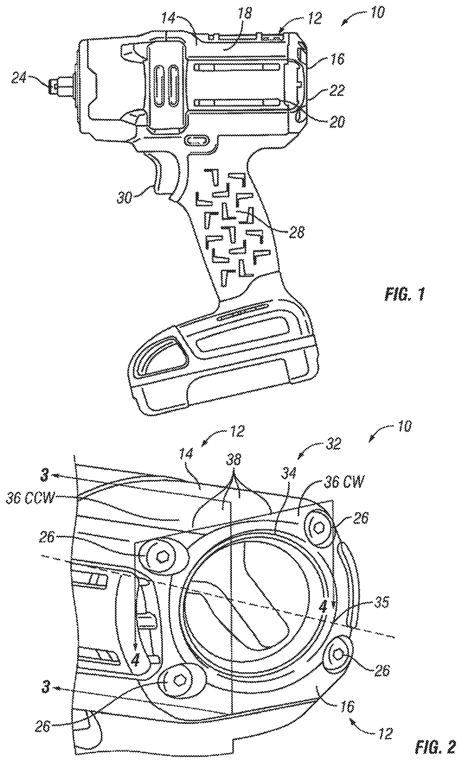
is a side elevation view of an illustrative power tool including a tool housing;
is a perspective view of a user interface provided on a rear portion of the tool housing of the power tool of with remaining portions of the tool housing omitted for the sake of clarity;
is a magnified sectional view, taken about line 3 - 3 of , of an embodiment of a sensor system supported by the rear portion of the power tool;
is a magnified sectional view, taken about line 3 - 3 of , of another embodiment of the sensor system supported by the rear portion of the power tool; and
is a magnified sectional view, taken about line 4 - 4 of , of the sensor system of .
DETAILED DESCRIPTION OF THE DRAWINGS
While the concepts of the present disclosure are susceptible to various modifications and alternative forms, specific exemplary embodiments thereof have been shown by way of example in the drawings and will herein be described in detail. It should be understood, however, that there is no intent to limit the concepts of the present disclosure to the particular forms disclosed, but on the contrary, the intention is to cover all modifications, equivalents, and alternatives falling within the spirit and scope of the present disclosure.
Referring now to , an illustrative power tool 10 is shown. The power tool 10 is illustratively embodied as a cordless, electric power tool. In particular, the power tool 10 is shown in as a pistol-grip style cordless electric impact tool, which includes an impact mechanism in-line with an output of the tool. It should be appreciated, however, that in other embodiments, the power tool may be embodied as another type of impact tool or as a cordless, electric power tool that does not include an impact mechanism, such as an electric drill, drill driver, ratchet, saw, or the like.
The illustrative power tool 10 includes a tool housing 12 as shown in . The tool housing 12 includes a body 14 and a cap 16 . The body 14 defines an interior space 18 in which a motive source 20 of the power tool 10 is positioned. The cap 16 is coupled to the body 14 when the power tool 10 is assembled to close off the interior space 18 and define an end 22 that is positioned opposite an output end 24 of the power tool 10 . The cap 16 is coupled to the body 14 using fasteners 26 (best seen in ) that extend through the cap 16 and into the interior space 18 . It is appreciated that motive source 20 may be an electric motor (either corded or cordless) or a pneumatic air motor.
The tool housing 12 defines a handle 28 on which a trigger 30 is provided as shown in . The trigger 30 is used to turn the motive source 20 on/off in use of the power tool 10 . It is appreciated that the trigger may include a button, be touch sensitive, or employ a like switch. A user interface 32 spaced from the trigger 30 is also provided on the tool housing 12 , specifically on the cap 16 , as best seen in . In the illustrative embodiment, the user interface 32 is used to select one of a plurality of modes of operation of the power tool 10 . For instance, in some embodiments, the user interface 32 may be used to select a particular mode of operation from among those described in U.S. Provisional Patent Application Ser. No. 62/171,504, filed Jun. 5, 2015. In other embodiments, the user interface 32 may simply regulate the maximum power supplied to the motive source 20 when the trigger 30 is fully depressed in use of the power tool 10 .
Referring now to , the user interface 32 is shown in greater detail. The user interface 32 is supported by the tool housing 12 and is illustratively embodied as, or otherwise includes, a control knob 34 . It should be appreciated, however, that in other embodiments, the user interface 32 may be embodied as a dial, push button, switch, or other control, and the dial, push button, switch, or other control, as well as components associated therewith, may be supported by the tool housing 12 .
The control knob 34 is accessible from the exterior of the tool housing 12 , and the control knob 34 is engaged with the cap 16 (best seen in ) and rotatable about a knob axis 36 between a number of mode positions 38 . Operation of the motive source 20 when the control knob 34 is in one of the mode positions 38 is different from the operation of the motive source 20 when the control knob 34 is in any of the other mode positions 38 . In the illustrative embodiment, the mode positions 38 include four different positions. It should be appreciated, however, that in other embodiments, the control knob 34 may be moved between more or less than four mode positions 38 .
Referring now to , the body 14 and the cap 16 of the tool housing 12 are broken away to show components of the motive source 20 . The motive source 20 is illustratively embodied as a brushless DC electric motor. The motive source 20 includes a rotor 40 configured to drive an output shaft 42 to output mechanical power and a stationary component (i.e., a stator) 44 that extends around the rotor 40 .
Motive source 20 such as a motor also includes a rear endbell 46 that abuts the control knob 34 and front endbell (not shown) that is spaced from the rear endbell 46 and positioned closer to the output end 24 of the power tool 10 than the rear endbell 46 . The rotor 40 and the stator 44 are positioned between the two endbells. The front endbell and the rear endbell 46 cooperate to align the rotor 40 and the stator 44 so that the rotor 40 and the stator 44 extend parallel to a central axis 48 of the motor 20 . The rear endbell 46 illustratively includes piloting features and indexing features that interface with the control knob 34 , as shown and described in U.S. Provisional Patent Application Ser. No. 62/171,673, filed Jun. 5, 2015. The piloting features interface with the control knob 34 to guide rotation of the control knob 34 relative to the tool housing 12 about the knob axis 36 between the mode positions 38 .
Motive source 20 includes a printed circuit board (PCB) 50 positioned near the rear endbell 46 and configured to provide motor control of the motive source 20 . Typically, the PCB 50 is used to support electrical components of the motive source 20 , such as sensors used to detect rotor position and terminals for the motor windings. The illustrative PCB 50 is annular in shape and fixed to the motor 20 with one or more fasteners 52 . The PCB 50 includes an outer side 56 configured to face the rear endbell 46 and an opposing inner side 54 . The terminals for the motor windings (not shown) are positioned on the inner side 54 of the PCB 50 . Additionally, in some embodiments, rotor position sensors 58 (e.g., Hall-effect sensors) are positioned on the inner side 54 of the PCB 50 near the rotor 40 and are configured to detect the position of the rotor 40 .
As illustrated in , a sensor system 60 for determining the mode position 38 of the control knob 34 is integrated into the PCB 50 and the control knob 34 . The sensor system 60 is configured to detect an input selected by the user via the control knob 34 and communicate that selection to a controller of the power tool 10 . The sensor system 60 includes one or more sensors 62 positioned on the outer side 56 of the PCB 50 and one or more sensor actuators 64 positioned on the control knob 34 . In the illustrative embodiment shown in , the one or more sensors 62 are embodied as Hall-effect sensors 62 positioned on the outer side 56 of the PCB 50 at locations corresponding to several mode positions 38 of the control knob 34 . Additionally, in the illustrative embodiment of , the one or more sensor actuators 64 are embodied as one or more permanent magnets 64 configured to generate magnetic fields that induce a voltage response in the corresponding Hall-effect sensors 62 . By incorporating the sensor system 60 directly into the PCB 50 , the complexity of the power tool 10 may be reduced by eliminating an additional PCB board associated solely with the user interface 32 of the power tool 10 . Because the illustrative Hall-effect sensors 62 are contactless, the user interface 32 of the power tool 10 may be better able to withstand the vibrational forces induced by the illustrative impact tool, in embodiments using Hall-effect sensors for both the sensor system 60 of the user interface 32 and the rotor position sensors 58 of the motor 20 , the PCB 50 may include shielding (e.g., steel shielding) to prevent interference between the permanent magnets 64 of the control knob 34 and the rotor position sensors 58 .
In the illustrative embodiment, three Hall-effect sensors 62 are mounted on the outer side 56 of the PCB 50 and a single permanent magnet 64 is positioned in the control knob 34 adjacent to the outer side 56 of the PCB 50 . The piloting and indexing features of the control knob 34 are configured to position the permanent magnet 64 near the corresponding Hall-effect sensors 62 that corresponds to a particular mode position 38 . For example, when the control knob 34 is in a first mode position 38 , the magnet 64 is adjacent to a first Hall-effect sensor 62 and the magnetic field generated by the magnet 64 excites the first Hall-effect sensor 62 to indicate to the controller of the power tool 10 to operate in a first mode of operation. Similarly, a second mode position 38 corresponds to a second Hall-effect sensor 62 and a third mode position 38 corresponds to a third Hall-effect sensor 62 . When the control knob 34 is in a fourth mode position 38 , the magnet 64 is not positioned to excite any of the three Hall-effect sensors 62 . The controller of the power tool 10 causes the motive source 20 to operate in a fourth mode of operation when no signal from any Hall-effect sensor is detected. It should be appreciated that the first, second, third, and fourth mode positions 38 need not be positioned in sequential order in the power tool 10 . In an alternate embodiment for forth mode position 38 , magnet 64 may be positioned adjacent a fourth Hall-effect sensor 62 where the magnetic field generated by magnet 64 excites fourth Hall-effect sensor 62 to indicate to the controller of power tool 10 to operate in the fourth mode of operation. In illustrative embodiments, a different configuration of sensor actuators 64 and sensors 62 may be used. For example, the control knob 34 may include two permanent magnets 64 and the PCB 50 may include two Hall-effect sensors 62 that cooperate to define four separate modes of operation of the power tool 10 . It will also be appreciated that the user interface 32 may be designed to have any number of mode positions 38 .
show another embodiment of the sensor system 60 where the one or more sensors 62 include an arcuate potentiometer 66 and the one or more sensor actuators 64 include a plunger 68 . The potentiometer 66 is positioned on the outer side 56 of the PCB 50 and includes a membrane 70 that includes a first end 72 and a second end 74 . The potentiometer 66 is configured to change an output current based on a variable resistance determined by the interaction of the plunger 68 with the membrane 70 . The plunger 68 is positioned on the control knob 34 such that it contacts the membrane 70 and is configured to change the resistance of the potentiometer 66 based on the location of the plunger 68 on the membrane 70 . For example, if the plunger 68 is contacting the membrane 70 at the first end 72 , the potentiometer 66 may have a first resistance that the controller interprets to indicate that the power tool 10 is to operate in a first mode of operation. Similarly, different locations of the plunger 68 on the membrane 70 cause the potentiometer 66 to have a second, third, or fourth resistance that corresponds to a second, third, or fourth mode of operation respectively. As noted above, it should be appreciated that, in some embodiments, the power tool 10 may include more (or less) than four mode positions 38 and more (or less) than four modes of operation that the user may select. Both the Hall-effect sensor embodiment of the sensor system 60 and the potentiometer embodiment of the sensor system 60 are adapted to withstand the vibrations that may be present in an impact tool.
In other embodiments, the sensor system 60 may be embodied as magnetic transducers (e.g., Hall-effect sensors, switches, angle sensors etc.), linear and rotary membrane potentiometers, or mechanical contacts which would be used for detecting the mode of operation selected by the user and communicating that selection to the controller of the power tool 10 .
While certain illustrative embodiments have been described in detail in the figures and the foregoing description, such an illustration and description is to be considered as exemplary and not restrictive in character, it being understood that only illustrative embodiments have been shown and described and that all changes and modifications that come within the spirit of the disclosure are desired to be protected. There are a plurality of advantages of the present disclosure arising from the various features of the apparatus, systems, and methods described herein. It will be noted that alternative embodiments of the apparatus, systems, and methods of the present disclosure may not include all of the features described yet still benefit from at least some of the advantages of such features. Those of ordinary skill in the art may readily devise their own implementations of the apparatus, systems, and methods that incorporate one or more of the features of the present disclosure.
Figures (3)
Citations
This patent cites (471)
- US288701
- US1495153
- US1892997
- US2531800
- US2543979
- US2637825
- US2855679
- US2858701
- US2984210
- US3221192
- US3225232
- US3336490
- US3353078
- US3440465
- US3451492
- US3462623
- US3476960
- US3572447
- US3578091
- US3592087
- US3611095
- US3643749
- US3703933
- US3710873
- US3741313
- US3760209
- US3835934
- US3894254
- US3908766
- US3920082
- US4032806
- US4156821
- US4284109
- US4292571
- US4307325
- US4412158
- US4454459
- US4506743
- US4510404
- US4513381
- US4514172
- US4597419
- US4661756
- US4791833
- US4795932
- US4838361
- US4893942
- US4978877
- US4991472
- US5014793
- US5105130
- US5138243
- US5200658
- US5203242
- US5360072
- US5365155
- US5473519
- US5525842
- US5526460
- US5531278
- US5553675
- US5561734
- US5563482
- US5567999
- US5712543
- US5714815
- US5714861
- US5738177
- US5804936
- US5818142
- US5897454
- US5992257
- US5998897
- US6037724
- US6043575
- US6239521
- US6250399
- US6318189
- US6353705
- US6359355
- US6424799
- US6508313
- US6511200
- US6536536
- US6598684
- US6607041
- US6687567
- US6691796
- US6713905
- US6725945
- US6814461
- US6933632
- US6945337
- US6948647
- US6968908
- US6988897
- US7033137
- US7058291
- US7090032
- US7109675
- US7112934
- US7152329
- US7155986
- US7201235
- US7213500
- US7235940
- US7236243
- US7237622
- US7311027
- US7322427
- US7331406
- US7334648
- US7372228
- US7397153
- US7398834
- US7404450
- US7419013
- US7494437
- US7578357
- US7588094
- US7600577
- US7607493
- US7665392
- US7673370
- US7677752
- US7705482
- US7712546
- US7717192
- US7718109
- US7817384
- US7821217
- US7839112
- US7882899
- US7928615
- US7942211
- US7980320
- US8016048
- US8091650
- US8122971
- US8197379
- US8210275
- US8267924
- US8294399
- US8303449
- US8316741
- US8316958
- US8317350
- US8371708
- US8381830
- US8415911
- US8430180
- US8430182
- US8496366
- US8511399
- US8528658
- US8541914
- US8584770
- US8593020
- US8607893
- US8636081
- US8674640
- US8708861
- US8714888
- US8727034
- US8746364
- US8757286
- US8800679
- US8807414
- US8820430
- US8919456
- US8939228
- US9089954
- US9193055
- US9217492
- US9220201
- US9271620
- US9314855
- US9321156
- US9385352
- US9415448
- US9463563
- US9566692
- US9579785
- US9739366
- US9827660
- US9950417
- US10046450
- US10052733
- US10064639
- US10418879
- US10513025
- US10518879
- US10528073
- US10615670
- US20020001434
- US20020018474
- US20020020538
- US20020050364
- US20020096342
- US20020108474
- US20020131267
- US20020153856
- US20020172035
- US20020185514
- US20030002934
- US20030121679
- US20030136570
- US20030149508
- US20040035495
- US20040200628
- US20040211573
- US20040217727
- US20050040206
- US20050135084
- US20050183870
- US20050224242
- US20050257945
- US20050263304
- US20050279197
- US20060012584
- US20060071433
- US20060109246
- US20060118314
- US20060125333
- US20060185865
- US20060185869
- US20060201612
- US20060226718
- US20060237205
- US20060243469
- US20070000676
- US20070074883
- US20070180959
- US20070193762
- US20070222310
- US20070256847
- US20080000665
- US20080025017
- US20080032848
- US20080048650
- US20080066941
- US20080122302
- US20090090763
- US20090098971
- US20090188688
- US20090200053
- US20090221222
- US20090308624
- US20100000846
- US20100163261
- US20100175902
- US20100200380
- US20100236800
- US20100252287
- US20100263890
- US20100282482
- US20100307782
- US20100326686
- US20110000688
- US20110024144
- US20110036605
- US20110048750
- US20110056715
- US20110073343
- US20110079407
- US20110109093
- US20110127059
- US20110132630
- US20110147028
- US20110147029
- US20110180290
- US20110188232
- US20110203819
- US20110248650
- US20110284256
- US20110308827
- US20110315417
- US20120013829
- US20120019080
- US20120055690
- US20120089131
- US20120090863
- US20120132449
- US20120138329
- US20120175142
- US20120205131
- US20120234568
- US20120273242
- US20120279736
- US20120292071
- US20120292472
- US20120318544
- US20120318549
- US20130014967
- US20130033217
- US20130056235
- US20130056236
- US20130062086
- US20130062088
- US20130062498
- US20130068491
- US20130075121
- US20130087355
- US20130105189
- US20130108385
- US20130126202
- US20130133912
- US20130153252
- US20130153253
- US20130161040
- US20130175066
- US20130186661
- US20130186666
- US20130193891
- US20130206434
- US20130206435
- US20130213680
- US20130220655
- US20130228353
- US20130228356
- US20130240230
- US20130247706
- US20130267374
- US20130269961
- US20130270932
- US20130270934
- US20130274797
- US20130284480
- US20130292147
- US20130313925
- US20130327552
- US20130331994
- US20130333904
- US20130333910
- US20130342084
- US20140015383
- US20140026723
- US20140036482
- US20140058390
- US20140069676
- US20140096985
- US20140100687
- US20140102741
- US20140138111
- US20140158390
- US20140166326
- US20140182869
- US20140182870
- US20140209342
- US20140290973
- US20140338503
- US20140365012
- US20140367134
- US20150014010
- US20150041163
- US20150047866
- US20150047943
- US20150122521
- US20150122523
- US20150122524
- US20150129248
- US20150136433
- US20150144365
- US20150151424
- US20150171654
- US20150197003
- US20150202759
- US20150209948
- US20150222162
- US20150328760
- US20150336249
- US20160102762
- US20160118201
- US20160131353
- US20160176027
- US20160193673
- US20160250738
- US20160311094
- US20160354889
- US20160354905
- US20160354915
- US20170222382
- US20170225309
- US20180161951
- US2650085
- US1575218
- US1583370
- US101253015
- US103481251
- US103989497
- US104162880
- US104676315
- US19518591
- US102004051913
- US102005015900
- US202006018761
- US102006000543
- US102008020173
- US102012211914
- US102015006042
- US202016104126
- US0271903
- US0585541
- US0585541
- US0585541
- US0808018
- US0911119
- US1426989
- US1524085
- US1595649
- US1595650
- US1867438
- US1943061
- US1982798
- US1207016
- US2042271
- US2062670
- US2062700
- US1524084
- US2075094
- US1447177
- US2256899
- US2184138
- US2524775
- US2535150
- US2687338
- US752251
- US1068990
- US1413293
- US2396390
- US2514261
- USH08193896
- USH08294878
- US2000218561
- US2002331427
- US2004202600
- US2004239681
- US2005254400
- US2006272488
- US2006312210
- US2009269137
- US2010012585
- US2011031369
- US2011067910
- US2011230272
- US2012035358
- US2012149669
- US2360786
- US201231843
- US9853959
- US0064639
- US0144776
- US0154865
- US0230624
- US2004029569
- USWO-2006111173
- US2009011633
- US2010110716
- US2011013852
- US2011099487
- US2011102559
- US2012002578
- US2012023452
- US2013037325
- US2013164905
- US2013183535
- US2014098256
- US2014108110
- US2014124859
- US2016196899
- US2058891