Display Device, Backlight Module, and Method for Assembling Backlight Module
Abstract
A backlight module includes a housing, a diffuser plate, an optical film, a holder and a light source. The housing has a groove. The groove is arranged along a periphery of the housing. The diffuser plate is disposed in the housing and has an edge located in the groove. The optical film is disposed on the diffuser plate and has a thru-hole. The holder is disposed in the groove of the housing and includes a holding portion and a hanging portion. The holding portion engages the edge of the diffuser plate. The hanging portion is connected to the holding portion and extends through the thru-hole of the optical film. The light source is disposed in the housing.
Claims (16)
1. A backlight module, comprising: a housing having a groove, the groove being arranged along a periphery of the housing; a diffuser plate disposed in the housing, wherein an edge of the diffuser plate is located in the groove of the housing; an optical film disposed on the diffuser plate and having a thru-hole; a holder disposed in the groove of the housing and comprising a holding portion and a hanging portion, wherein the holding portion engages the edge of the diffuser plate, wherein the hanging portion is connected to the holding portion and extends through the thru-hole of the optical film; and a light source disposed in the housing, wherein the diffuser plate has a first surface, a second surface and a third surface, the third surface is opposite to the first surface, the second surface is connected between the first surface and the third surface, the holding portion of the holder comprises a first covering portion and a second covering portion connected to the first covering portion, the first covering portion and the second covering portion contact the first surface and the second surface of the diffuser plate respectively, and the holding portion is spaced apart from the third surface of the diffuser plate.
5. A display device, comprising: a backlight module, comprising: a housing having a groove, the groove being arranged along a periphery of the housing, wherein the housing comprises a backplate portion, a sidewall portion, and a platform portion that collectively defines the groove, the platform portion is opposite to the backplate portion and has a surface away from the backplate portion, and the sidewall portion is connected to the backplate portion and the platform portion; a diffuser plate disposed in the housing, wherein an edge of the diffuser plate is located in the groove of the housing; an optical film disposed on the diffuser plate and having a thru-hole, wherein an edge of the optical film is located in the groove of the housing; a holder disposed in the groove of the housing and comprising a holding portion and a hanging portion, wherein the holding portion engages the edge of the diffuser plate, wherein the hanging portion is connected to the holding portion and extends through the thru-hole of the optical film; and a light source disposed in the housing; and a display panel disposed on the surface of the platform portion of the housing of the backlight module.
10. A method for assembling a backlight module, comprising: fixedly engaging a holder to an edge of a diffuser plate; placing an optical film over the diffuser plate and fitting the optical film onto a hanging portion of the holder, such that the holder, the diffuser plate and the optical film are combined into a piece, wherein the hanging portion extends through a thru-hole of the optical film; and inserting the combined piece of the holder, the diffuser plate and the optical film into a housing, such that the holder and the edge of the diffuser plate are received in a groove of the housing, wherein the groove is arranged along a periphery of the housing, wherein the housing comprises a backplate portion, a sidewall portion, and a platform portion that collectively defines the groove, the platform portion is opposite to the backplate portion and has a surface away from the backplate portion, and the sidewall portion is connected to the backplate portion and the platform portion.
Show 13 dependent claims
2. The backlight module of claim 1 , wherein the edge of the diffuser plate has at least one notch, and the holding portion of the holder is disposed in the notch.
3. The backlight module of claim 1 , wherein the hanging portion of the holder is connected to the first covering portion and extends through the diffuser plate.
4. The backlight module of claim 1 , wherein the light source, the diffuser plate and the optical film are arranged in a first direction, the housing comprises a platform portion and a sidewall portion, the platform portion is configured to support a display panel, the sidewall portion is connected to the platform portion, and the sidewall portion extends beyond the platform portion in the first direction.
6. The display device of claim 5 , wherein the light source, the diffuser plate and the optical film of the backlight module are arranged in a first direction, wherein the sidewall portion of the housing extends along a periphery of the display panel, and the sidewall portion extends beyond a display surface of the display panel or is flush with the display surface in the first direction.
7. The backlight module of claim 5 , wherein the holding portion of the holder fixedly clamps the diffuser plate.
8. The backlight module of claim 5 , wherein the diffuser plate has a first surface and a second surface opposite to the first surface, the holding portion of the holder comprises a first covering portion, a second covering portion and a third covering portion, the first covering portion and the second covering portion contact the first surface and the second surface of the diffuser plate respectively, and the third covering portion is connected between the first covering portion and the second covering portion.
9. The backlight module of claim 5 , wherein the hanging portion of the holder comprises a hook structure, and the hook structure is located on an end of the hanging portion away from the holding portion.
11. The method of claim 10 , wherein the diffuser plate and the optical film are arranged in a first direction, and wherein the step of inserting the combined piece of the holder, the diffuser plate and the optical film into the housing comprises: sliding the combined piece of the holder, the diffuser plate and the optical film along a second direction into the groove, wherein the second direction is substantially perpendicular to the first direction.
12. The method of claim 10 , wherein the diffuser plate and the optical film are adjacent to each other.
13. The method of claim 10 , wherein the holder further comprises a holding portion, and the holding portion fixedly clamps the diffuser plate.
14. The method of claim 10 , wherein the diffuser plate has a first surface and a second surface opposite to the first surface, the holder further comprises a holding portion, the holding portion comprises a first covering portion, a second covering portion and a third covering portion, the first covering portion and the second covering portion contact the first surface and the second surface of the diffuser plate respectively, and the third covering portion is connected between the first covering portion and the second covering portion.
15. The method of claim 10 , wherein the hanging portion comprises a hook structure, the holder further comprises a holding portion, and the hook structure is located on an end of the hanging portion away from the holding portion.
16. The method of claim 10 , further comprising: disposing a display panel on the surface of the platform portion away from the backplate portion.
Full Description
Show full text →
RELATED APPLICATIONS
This application claims priority to U.S. Provisional Application Ser. No. 63/165,166 filed Mar. 24, 2021, and Taiwan Application Serial Number 110141573, filed Nov. 8, 2021, the disclosures of which are incorporated herein by reference in their entireties.
BACKGROUND
Technical Field
The present disclosure relates to a display device, a backlight module, and a method for assembling backlight module.
Description of Related Art
A backlight module typically includes at least one optical film to distribute the light emitted by the light source evenly across the display area. Conventional backlight modules sacrifice the appearance of the backplate in order to incorporate mechanisms for holding the optical film. For example, incorporating mechanisms for holding the optical film might require one or more openings to be formed on the backplate. These conventional approaches may also cause the leakage of light from the backplate. As a result, display devices using these conventional backlight modules are required to add an outer part to improve their appearances, as well as to prevent light leakage.
SUMMARY
In view of the foregoing, one of the objects of the present disclosure is to provide a backlight module that can achieve the fixing of the optical film without making sacrifice in its appearance.
To achieve the objective stated above, in accordance with an embodiment of the present disclosure, a backlight module includes a housing, a diffuser plate, an optical film, a holder and a light source. The housing has a groove. The groove is arranged along a periphery of the housing. The diffuser plate is disposed in the housing, and an edge of the diffuser plate is located in the groove. The optical film is disposed on the diffuser plate and has a thru-hole. The holder is disposed in the groove of the housing and includes a holding portion and a hanging portion. The holding portion engages the edge of the diffuser plate. The hanging portion is connected to the holding portion and extends through the thru-hole of the optical film. The light source is disposed in the housing.
In one or more embodiments of the present disclosure, the holding portion of the holder fixedly clamps the diffuser plate.
In one or more embodiments of the present disclosure, the diffuser plate has a first surface and a second surface opposite to the first surface. The holding portion of the holder includes a first covering portion, a second covering portion and a third covering portion. The first covering portion and the second covering portion contact the first surface and the second surface of the diffuser plate respectively. The third covering portion is connected between the first covering portion and the second covering portion.
In one or more embodiments of the present disclosure, the edge of the diffuser plate has at least one notch, and the holding portion of the holder is disposed in the notch.
In one or more embodiments of the present disclosure, the hanging portion of the holder includes a hook structure. The hook structure is located on an end of the hanging portion away from the holding portion.
In one or more embodiments of the present disclosure, the diffuser plate has a first surface, a second surface and a third surface. The third surface is opposite to the first surface. The second surface is connected between the first surface and the third surface. The holding portion of the holder includes a first covering portion and a second covering portion connected to the first covering portion. The first covering portion and the second covering portion contact the first surface and the second surface of the diffuser plate respectively. The holding portion is spaced apart from the third surface of the diffuser plate.
In one or more embodiments of the present disclosure, the hanging portion of the holder is connected to the first covering portion and extends through the diffuser plate.
In one or more embodiments of the present disclosure, the light source, the diffuser plate and the optical film are arranged in a first direction. The housing includes a platform portion and a sidewall portion. The platform portion is configured to support a display panel. The sidewall portion is connected to the platform portion, and the sidewall portion extends beyond the platform portion in the first direction.
In accordance with an embodiment of the present disclosure, a display device includes the aforementioned backlight module and a display panel. The display panel is disposed on a platform portion of the housing of the backlight module.
In one or more embodiments of the present disclosure, the light source, the diffuser plate and the optical film of the backlight module are arranged in a first direction. The housing further includes a sidewall portion connected to the platform portion. The sidewall portion extends along a periphery of the display panel, and the sidewall portion extends beyond a display surface of the display panel or is flush with the display surface in the first direction.
In accordance with an embodiment of the present disclosure, a method for assembling a backlight module includes: fixedly engaging a holder to an edge of a diffuser plate; placing an optical film over the diffuser plate and fitting the optical film onto a hanging portion of the holder, such that the holder, the diffuser plate and the optical film are combined into a piece; and inserting the combined piece of the holder, the diffuser plate and the optical film into a housing, such that the holder and the edge of the diffuser plate are received in a groove of the housing, wherein the groove is arranged along a periphery of the housing.
In one or more embodiments of the present disclosure, the diffuser plate and the optical film are arranged in a first direction, and the step of inserting the combined piece of the holder, the diffuser plate and the optical film into the housing includes: sliding the combined piece of the holder, the diffuser plate and the optical film along a second direction into the groove, wherein the second direction is substantially perpendicular to the first direction.
In sum, in the backlight module of the present disclosure, the diffuser plate and the optical film are combined by the holder, and the housing of the backlight module is a unitary structure and is formed with a groove. The holder and the edges of the diffuser plate and the optical film can be received in the groove. By this arrangement, the backlight module of the present disclosure can hold the diffuser plate and the optical film in the housing while maintaining the completeness of the appearance of the housing. Adding an outer part to the backlight module to improve its appearance and to prevent light leakage, as in conventional backlight modules, would not be necessary.
BRIEF DESCRIPTION OF THE DRAWINGS
To make the objectives, features, advantages, and embodiments of the present disclosure, including those mentioned above and others, more comprehensible, descriptions of the accompanying drawings are provided as follows.
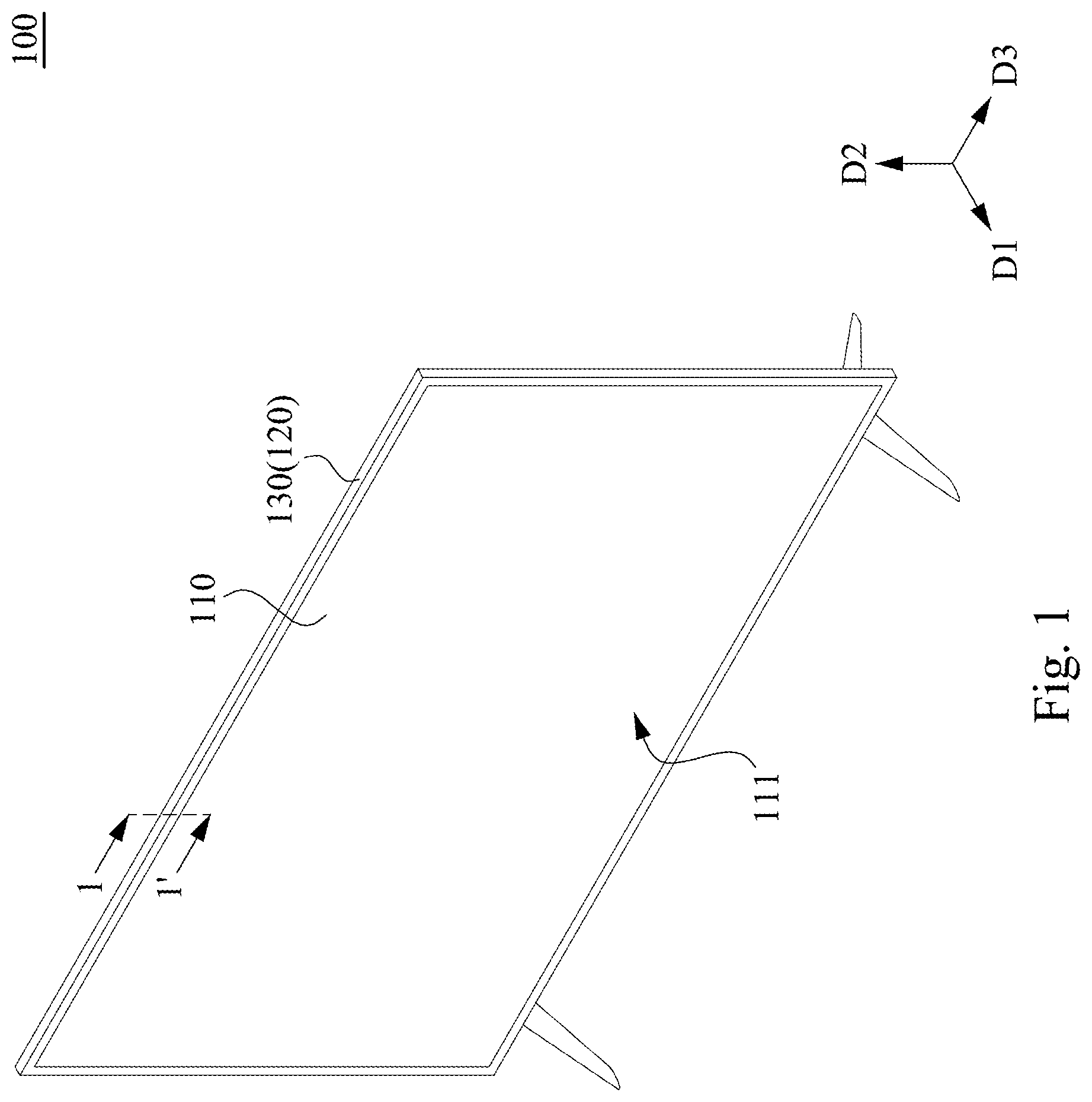
illustrates a perspective view of a display device in accordance with an embodiment of the present disclosure;
illustrates an enlarged sectional view of the display device shown in taken along line segment 1 - 1 ′;
illustrates an exploded view of some components of the display device shown in ;
to 6 illustrate sectional views of the display device shown in at various stages of the assembly process;
illustrates an exploded view of a diffuser plate, an optical film and a holder in accordance with another embodiment of the present disclosure;
illustrates an assembled view of the diffuser plate, the optical film and the holder shown in ;
illustrates an exploded view of a diffuser plate, an optical film and a holder in accordance with another embodiment of the present disclosure; and
illustrates an assembled view of the diffuser plate, the optical film and the holder shown in .
DETAILED DESCRIPTION
For the completeness of the description of the present disclosure, reference is made to the accompanying drawings and the various embodiments described below. Various features in the drawings are not drawn to scale and are provided for illustration purposes only. To provide full understanding of the present disclosure, various practical details will be explained in the following descriptions. However, a person with an ordinary skill in relevant art should realize that the present disclosure can be implemented without one or more of the practical details. Therefore, the present disclosure is not to be limited by these details.
Reference is made to . A display device 100 includes a display panel 110 (e.g., an LCD panel) and a backlight module 120 . The display panel 110 has a first surface 111 and a second surface 112 (depicted in ). The second surface 112 is opposite to the first surface 111 . The first surface 111 is configured to display a screen. In other words, the first surface 111 is a display surface of the display panel 110 . The backlight module 120 includes a housing 130 . The display panel 110 is disposed on the housing 130 of the backlight module 120 , with the first surface 111 facing away from the backlight module 120 . The backlight module 120 is configured to illuminate the display panel 110 , such that the display panel 110 can produce a visible image.
As shown in , for the convenience of description, a first direction D 1 is defined as the normal direction of the first surface 111 of the display panel 110 , a second direction D 2 is defined as the direction along which the short sides of the display device 100 extends (e.g., upward direction in ), and a third direction D 3 is defined as the direction along which the long sides of the display device 100 extends (e.g., horizontal direction in ). In some embodiments, the first direction D 1 , the second direction D 2 and the third direction D 3 are mutually orthogonal.
Reference is made to . The housing 130 has an opening 139 facing the display panel 110 . The backlight module 120 further includes a light source 141 disposed in the housing 130 . The light source 141 faces the opening 139 and is oriented towards the first direction D 1 . As a result, the light source 141 can emit light towards the display panel 110 through the opening 139 of the housing 130 . In some embodiments, the light source 141 includes one or more LEDs. In some embodiments, the light source 141 includes one or more LED light strips or LED light boards.
As shown in , in some embodiments, the backlight module 120 further includes a reflector sheet 142 . The reflector sheet 142 partially covers an inner surface of the housing 130 and is configured to reflect the light emitted to the inner surface of the housing 130 towards the display panel 110 . In some embodiments, the reflector sheet 142 has one or more openings 143 , and the light source 141 is disposed in the openings 143 of the reflector sheet 142 .
As shown in , in some embodiments, the housing 130 includes a backplate portion 131 , a sidewall portion 132 and a platform portion 133 . The backplate portion 131 is configured to support the light source 141 and the reflector sheet 142 . Specifically, the light source 141 may be disposed on a bottom surface B of the backplate portion 131 , and the reflector sheet 142 may cover the bottom surface B and side surfaces of the backplate portion 131 . The platform portion 133 is opposite to the backplate portion 131 and is located on at least one side of the opening 139 of the housing 130 . The platform portion 133 is configured to support the display panel 110 . For example, the display panel 110 may be fixedly attached to a side of the platform portion 133 away from the backplate portion 131 via an adhesive layer A. The sidewall portion 132 is connected to the backplate portion 131 and the platform portion 133 . The backplate portion 131 , the sidewall portion 132 and the platform portion 133 collectively defines a groove 138 . The groove 138 is arranged along a periphery of the housing 130 .
In some embodiments, the housing 130 is provided with the sidewall portion 132 and the platform portion 133 on the top, left and right sides, which form the groove 138 with the backplate portion 131 on the top, left and right sides of the housing 130 (i.e., on the top, left and right of the housing 130 when the housing 130 is held upright, as shown in ). In some embodiments, the housing 130 is a unitary metallic housing.
As shown in , the backlight module 120 further includes a diffuser plate 151 and at least one optical film 152 , both of which are disposed in the housing 130 . The light source 141 , the diffuser plate 151 and the optical film 152 are arranged along the first direction D 1 . The diffuser plate 151 and the optical film 152 are located between the light source 141 and the display panel 110 . The optical film 152 is disposed on the diffuser plate 151 . The diffuser plate 151 and the optical film 152 each has at least one edge located in the groove 138 of the housing 130 .
In some embodiments, the diffuser plate 151 and the optical film 152 may be fixedly combined via a double sided tape or other suitable adhesives (not depicted). In some embodiments, the adhesive may be provided between the diffuser plate 151 and the optical film 152 and proximate the peripheries of the diffuser plate 151 and the optical film 152 . In some embodiments, the diffuser plate 151 is fixedly attached to the housing 130 (e.g., the diffuser plate 151 may be adhered to the housing 130 via an adhesive material).
With reference to and additionally to , the backlight module 120 further includes at least one holder 160 . The holder 160 is disposed in the housing 130 and is configured to strengthen the combination of the diffuser plate 151 and the optical film 152 . In some embodiments, the holder 160 is a metallic part and may be formed by means of sheet metal bending. In some embodiments, the holder 160 includes stainless steel or other suitable metal materials.
As shown in , specifically, the holder 160 is disposed in the groove 138 of the housing 130 (in other words, the holder 160 is located between the backplate portion 131 and the platform portion 133 of the housing 130 ) and includes a holding portion 161 and a hanging portion 162 connected to the holding portion 161 . The holding portion 161 engages an edge of the diffuser plate 151 . The optical film 152 has a thru-hole H. The hanging portion 162 extends through the thru-hole H of the optical film 152 .
By this arrangement, the backlight module 120 of the present disclosure can hold the diffuser plate 151 and the optical film 152 in the housing 130 while maintaining the completeness of the appearance of the housing 130 . Adding an outer part to the backlight module 120 to improve its appearance and to prevent light leakage, as in conventional backlight modules, would not be necessary. Eliminating the outer part results in simplified structure of the backlight module 120 , and can facilitate thin bezel design for the display device 100 .
In some embodiments, the holder 160 is disposed on the upper edges of the diffuser plate 151 and the optical film 152 , wherein the upper edges refer to the uppermost edges of the diffuser plate 151 and the optical film 152 when the display device 100 is in the upright position (i.e., the position shown in ). When in use, the display device 100 is usually kept in the upright position, during which time the holder 160 can support the optical film 152 from the top. As a result, even if the adhesive between the diffuser plate 151 and the optical film 152 fails (e.g., due to temperature or other environmental factors), the holder 160 can maintain the position of the optical film 152 by hanging the optical film 152 , such that the optical film 152 remains aligned with the diffuser plate 151 .
In some embodiments, the backlight module 120 includes a plurality of holders 160 arranged along the upper edges of the diffuser plate 151 and the optical film 152 (i.e., the holders 160 are arranged along the third direction D 3 ) and spaced apart from one another. The number and the spacing of the holders 160 may be set based on the size of the display device 100 or the display panel 110 .
As shown in , in some embodiments, the holding portion 161 of the holder 160 fixedly clamps the diffuser plate 151 . In some embodiments, the diffuser plate 151 has three surfaces C 1 , C 2 and C 3 . The surface C 3 is opposite to the surface C 1 . The surface C 2 is connected between the surfaces C 1 and C 3 . The holding portion 161 of the holder 160 includes three covering portions 161 A, 161 B and 161 C. The covering portion 161 C is opposite to the covering portion 161 A. The covering portion 161 B is connected between the covering portions 161 A and 161 C, and the covering portion 161 B form a concavity with the covering portions 161 A and 161 C. The covering portions 161 A and 161 C contact the surfaces C 1 and C 3 of the diffuser plate 151 respectively, thereby clamping the diffuser plate 151 . In some embodiments, the covering portion 161 B of the holding portion 161 contacts the surface C 2 of the diffuser plate 151 . In some embodiments, the hanging portion 162 is connected to the covering portion 161 C and extends in a direction away from the covering portion 161 A or the diffuser plate 151 .
As shown in , in some embodiments, the edge of the diffuser plate 151 has at least one notch 153 , and the holding portion 161 of the holder 160 is disposed in the notch 153 . By this arrangement, the holder 160 can securely engage with the diffuser plate 151 . In some embodiments, the depth of the notch 153 is greater than or equal to a thickness of the holder 160 (e.g., the thickness of the covering portion 161 B). By this arrangement, when the holder 160 is combined with the diffuser plate 151 , the combined structure would not have any protrusion on its edge.
As shown in , in some embodiments, the hanging portion 162 of the holder 160 includes a hook structure 163 . The hook structure 163 is located on an end of the hanging portion 162 away from the holding portion 161 . The hook structure 163 can prevent the optical film 152 from falling off the hanging portion 162 . In some embodiments, the hanging portion 162 includes a first section 162 A and a second section 162 B. The first section 162 A is connected to the holding portion 161 . The second section 162 B is connected to the first section 162 A and is at an angle to the first section 162 A.
As shown in , in some embodiments, the sidewall portion 132 extends beyond the platform portion 133 in the first direction D 1 . By this arrangement, the sidewall portion 132 can serve as the bezel of the display device 100 . Since the housing 130 does not include any part that extends to a side of the display panel 110 adjacent to the first surface 111 , the user viewing the display device 100 from the front can only see the slim sidewall portion 132 on the outer side of the display panel 110 , making the display device 100 visually thin-bezeled.
As shown in , in some embodiments, the platform portion 133 has a surface 134 away from the backplate portion 131 , and the sidewall portion 132 has a tip 136 away from the backplate portion 131 . In the first direction D 1 , a distance between the tip 136 of the sidewall portion 132 and the bottom surface B of the backplate portion 131 is greater than a distance between the surface 134 of the platform portion 133 and the bottom surface B of the backplate portion 131 . In some embodiments, the sidewall portion 132 includes a bent portion 135 connected to the platform portion 133 . The bent portion 135 extends beyond the platform portion 133 in the first direction D 1 .
As shown in , in some embodiments, the sidewall portion 132 extends beyond the first surface 111 (i.e., the display surface) of the display panel 110 or is flush with the first surface 111 in the first direction D 1 . In some embodiments, in the first direction D 1 , the distance between the tip 136 of the sidewall portion 132 and the bottom surface B of the backplate portion 131 is greater than or equal to a distance between the first surface 111 of the display panel 110 and the bottom surface B of the backplate portion 131 .
Next, a method for assembling the backlight module 120 will be described with reference to to 6 . The method for assembling the backlight module 120 includes steps S 1 -S 5 .
As shown in , first, in step S 1 , fixedly engage the holder 160 to an edge of the diffuser plate 151 . In some embodiments, step S 1 includes: fixedly engaging the holding portion 161 of the holder 160 to the notch 153 on the edge of the diffuser plate 151 , such that the holding portion 161 is received in the notch 153 .
As shown in , next, in step S 3 , place the optical film 152 over the diffuser plate 151 and fit the optical film 152 onto the hanging portion 162 of the holder 160 , such that the holder 160 , the diffuser plate 151 and the optical film 152 are combined into a piece. In some embodiments, step S 3 includes: passing the hanging portion 162 of the holder 160 through the thru-hole H of the optical film 152 . In some embodiments, the method for assembling the backlight module 120 further includes: providing an adhesive between the diffuser plate 151 and the optical film 152 , so as to fixedly combine the diffuser plate 151 and the optical film 152 .
As shown in , last, in step S 5 , insert the combined piece of the holder 160 , the diffuser plate 151 and the optical film 152 into the housing 130 , such that the holder 160 , the edge of the diffuser plate 151 and an edge of the optical film 152 are received in the groove 138 of the housing 130 . In some embodiments, step S 5 includes: sliding the combined piece of the holder 160 , the diffuser plate 151 and the optical film 152 along the second direction D 2 (which is substantially perpendicular to the first direction D 1 ) into the groove 138 of the housing 130 . In some embodiments, the method for assembling the backlight module 120 further includes: fixedly attaching the diffuser plate 151 to the housing 130 .
Compared to conventional backlight modules, the method for assembling the backlight module 120 of the present disclosure, which includes first combining the diffuser plate 151 and the optical film 152 with the holder 160 and then inserting said three components into the housing 130 together, not only takes less time, but also reduces the risk of the diffuser plate 151 and the optical film 152 being scratched during the assembly process, resulting in improved production efficiency and quality.
In some embodiments, after the assembly of the backlight module 120 has completed, the display panel 110 may be fixedly attached to the platform portion 133 of the housing 130 to complete the assembly of the display device 100 .
Reference is made to . In the present embodiment, the covering portion 261 B of the holding portion 261 of the holder 260 includes a first section 264 A and a second section 264 B. The first section 264 A and the second section 264 B are each connected between the covering portions 161 A and 161 C. The first section 264 A and the second section 264 B are spaced apart from each other, such that a void is created between the first section 264 A and the second section 264 B. The edge of the diffuser plate 251 has two notches 253 . The first section 264 A and the second section 264 B are disposed in the two notches 253 respectively. The relatively protruded portion between the two notches 253 is inserted into the void between the first section 264 A and the second section 264 B.
As shown in , furthermore, the hanging portion 262 of the holder 260 may not be provided with a hook structure. In the present embodiment, the hanging portion 262 includes a straight section connected to the covering portion 161 C of the holding portion 261 . The hanging portion 262 may be perpendicular to the covering portion 161 C or at an angle to the covering portion 161 C.
Reference is made to . In the present embodiment, the holder 360 includes a substantially L-shaped holding portion 361 configured to abut against a corner of the diffuser plate 351 . Specifically, the holding portion 361 includes two covering portions 361 A and 361 B connected to each other. The covering portions 361 A and 361 B are configured to contact two neighboring surfaces C 1 and C 2 of the diffuser plate 251 , respectively, and are spaced apart from the surface C 3 of the diffuser plate 251 . The holder 360 of the present embodiment has a simple structure and is thus easy to manufacture (e.g., the sheet metal bending process can be simplified).
As shown in , in some embodiments, the hanging portion 362 of the holder 360 is connected to the covering portion 361 A. The hanging portion 362 and the covering portion 361 B are located on the same side of the covering portion 361 A. In other words, the hanging portion 362 and the covering portion 361 B extend in the same direction. In some embodiments, when the holder 360 is combined with the diffuser plate 351 and the optical film 152 , the covering portion 361 A is located on a side of the diffuser plate 351 away from the optical film 152 , and the hanging portion 362 extends through the diffuser plate 351 (e.g., via a notch 353 on an edge of the diffuser plate 351 ) and passes through the thru-hole H of the optical film 152 . By this arrangement, the holder 360 can securely engage with the diffuser plate 351 .
As shown in , in some embodiments, the covering portion 361 B includes a first section 364 A and a second section 364 B spaced apart from the first section 364 A. In a direction along which the first section 364 A and the second section 364 B are arranged, the hanging portion 362 is locate between the first section 364 A and the second section 364 B of the covering portion 361 B. By this arrangement, the holder 360 can stably rest against the diffuser plate 351 .
As shown in , in some embodiments, the diffuser plate 351 further includes two bosses 354 located on the two sides of the notch 353 . The first section 364 A and the second section 364 B of the covering portion 361 B are configured to abut against the two bosses 354 , respectively.
In sum, in the backlight module of the present disclosure, the diffuser plate and the optical film are combined by the holder, and the housing of the backlight module is a unitary structure and is formed with a groove. The holder and the edges of the diffuser plate and the optical film can be received in the groove. By this arrangement, the backlight module of the present disclosure can hold the diffuser plate and the optical film in the housing while maintaining the completeness of the appearance of the housing. Adding an outer part to the backlight module to improve its appearance and to prevent light leakage, as in conventional backlight modules, would not be necessary.
Although the present disclosure has been described by way of the exemplary embodiments above, the present disclosure is not to be limited to those embodiments. Any person skilled in the art can make various changes and modifications without departing from the spirit and the scope of the present disclosure. Therefore, the protective scope of the present disclosure shall be the scope of the claims as attached.
Figures (10)
Citations
This patent cites (11)
- US20130335947
- US20150338571
- US20200209687
- US103148459
- US204477811
- US215494450
- US20060134883
- USI247173
- US201626072
- USI589968
- US201816487