Camera Optical Lens Including Five Lenses of −+−+− Refractive Powers
Abstract
A camera optical lens includes a first lens, a second lens, a third lens, a fourth lens, and a fifth lens that are sequentially arranged from an object side to an image side. The camera optical lens satisfies following conditions: 0.50≤d2/d3≤2.00; −4.00≤R1/R2≤−1.50; and −8.00≤f3/f≤−4.00, where f denotes a focal length of the camera optical lens; f3 denotes a focal length of the third lens; R1 denotes a curvature radius of an object side surface of the first lens; R2 denotes a curvature radius of the image side surface of the first lens; d2 denotes an on-axis distance from an image side surface of the first lens to an object side surface of the second lens; and d3 denotes an on-axis thickness of the second lens. The camera optical lens has good optical performance while satisfying design requirements for ultra-thin, wide-angle lenses having large apertures.
Claims (10)
1. A camera optical lens, comprising, from an object side to an image side: a first lens having a negative refractive power; a second lens having a positive refractive power; a third lens having a negative refractive power; a fourth lens having a positive refractive power; and a fifth lens having a negative refractive power, wherein the camera optical lens satisfies following conditions: 0.50≤ d 2/ d 3≤2.00; −4.00≤ R 1/ R 2≤−1.50; and −8.00≤ f 3/ f≤− 4.00, where f denotes a focal length of the camera optical lens; f3 denotes a focal length of the third lens; R1 denotes a curvature radius of an object side surface of the first lens; R2 denotes a curvature radius of an image side surface of the first lens; d3 denotes an on-axis thickness of the second lens; and d2 denotes an on-axis distance from the image side surface of the first lens to an object side surface of the second lens.
Show 9 dependent claims
2. The camera optical lens as described in claim 1 , further satisfying a following condition: 0.60≤ f 4/ f≤ 1.50, where f4 denotes a focal length of the fourth lens.
3. The camera optical lens as described in claim 1 , further satisfying following conditions: −4.12≤ f 1/ f≤− 1.17; 0.10≤( R 1+ R 2)/( R 1− R 2)≤0.90; and 0.03≤ d 1/ TTL≤ 0.13, where f1 denotes a focal length of the first lens; d1 denotes an on-axis thickness of the first lens; and TTL denotes a total optical length from the object side surface of the first lens to an image plane of the camera optical lens along an optic axis.
4. The camera optical lens as described in claim 1 , further satisfying following conditions: 0.59≤ f 2/ f≤ 1.97; −0.51≤( R 3+ R 4)/( R 3− R 4)≤−0.01; and 0.05≤ d 3/ TTL≤ 0.25, where f2 denotes a focal length of the second lens; R3 denotes a curvature radius of the object side surface of the second lens; R4 denotes a curvature radius of an image side surface of the second lens; and TTL denotes a total optical length from the object side surface of the first lens to an image plane of the camera optical lens along an optic axis.
5. The camera optical lens as described in claim 1 , further satisfying following conditions: 2.03≤( R 5+ R 6)/( R 5− R 6)≤12.74; and 0.02≤ d 5/ TTL≤ 0.07, where R5 denotes a curvature radius of an object side surface of the third lens; R6 denotes a curvature radius of an image side surface of the third lens; d5 denotes an on-axis thickness of the third lens; and TTL denotes a total optical length from the object side surface of the first lens to an image plane of the camera optical lens along an optic axis.
6. The camera optical lens as described in claim 1 , further satisfying following conditions: 0.44≤( R 7+ R 8)/( R 7− R 8)≤1.38; and 0.10≤ d 7/ TTL≤ 0.31, where R7 denotes a curvature radius of an object side surface of the fourth lens; R8 denotes a curvature radius of an image side surface of the fourth lens; d7 denotes an on-axis thickness of the fourth lens; and TTL denotes a total optical length from the object side surface of the first lens to an image plane of the camera optical lens along an optic axis.
7. The camera optical lens as described in claim 1 , further satisfying following conditions: −7.14≤ f 5/ f≤− 0.50; 0.56≤( R 9+ R 10)/( R 9− R 10)≤7.12; and 0.05≤ d 9/ TTL≤ 0.16, where f5 denotes a focal length of the fifth lens; R9 denotes a curvature radius of an object side surface of the fifth lens; R10 denotes a curvature radius of an image side surface of the fifth lens; d9 denotes an on-axis thickness of the fifth lens; and TTL denotes a total optical length from the object side surface of the first lens to an image plane of the camera optical lens along an optic axis.
8. The camera optical lens as described in claim 1 , further satisfying a following condition: TTL/IH≤ 1.85, where TTL denotes a total optical length from the object side surface of the first lens to an image plane of the camera optical lens along an optic axis; and IH denotes an image height of the camera optical lens.
9. The camera optical lens as described in claim 1 , further satisfying a following condition: FOV≥119°, where FOV denotes a field of view of the camera optical lens.
10. The camera optical lens as described in claim 1 , further satisfying a following condition: 0.89≤ f 12/ f≤ 4.22, where f12 denotes a combined focal length of the first lens and the second lens.
Full Description
Show full text →
TECHNICAL FIELD
The present disclosure relates to the field of optical lens, and more particularly, to a camera optical lens suitable for handheld terminal devices such as smart phones or digital cameras, and camera devices such as monitors or PC lenses.
BACKGROUND
With the development of camera technology, camera optical lenses are widely applied in various electronic products, such as smart phones and digital cameras. For the purpose of portability, people are increasingly pursuing thinner and lighter electronic products, and thus miniature camera lenses with good imaging quality therefore have become a mainstream in the market.
In order to obtain better imaging quality, the lens that is conventionally equipped in mobile phone cameras adopts a three-piece or four-piece lens structure. However, with the development of technology and the increase of the diverse demands of users, and as the pixel area of photosensitive devices is becoming smaller and smaller and the requirement of the system on the imaging quality is improving constantly, a five-piece lens structure gradually emerges in lens designs. Although the common five-piece lens has good optical performance, its settings on refractive power, lens spacing and lens shape still have some irrationality, which results in that the lens structure cannot achieve a high optical performance while satisfying design requirements for wide-angle and ultra-thin lenses.
Therefore, it is urgent to provide a camera optical lens that has good optical performance and satisfies the requirements for wide-angle and ultra-thin design.
SUMMARY
In view of the above problems, the present disclosure provides a camera optical lens, which can solve the problem that conventional camera optical lenses are not fully ultra-thinned and wide-angled.
The present disclosure provides a camera optical lens, which includes, from an object side to an image side, a first lens having a negative refractive power, a second lens having a positive refractive power, a third lens having a negative refractive power, a fourth lens having a positive refractive power, and a fifth lens having a negative refractive power. The camera optical lens satisfies following conditions: 0.50≤d2/d3≤2.00; −4.00≤R1/R2≤−1.50; and −8.00≤f3/f≤−4.00, where f denotes a focal length of the camera optical lens; f3 denotes a focal length of the third lens; R1 denotes a curvature radius of an object side surface of the first lens; R2 denotes a curvature radius of the image side surface of the first lens; and d3 denotes an on-axis thickness of the second lens; d2 denotes an on-axis distance from an image side surface of the first lens to an object side surface of the second lens.
As an improvement, the camera optical lens further satisfies a following condition of 0.60≤f4/f≤1.50, where f4 denotes a focal length of the fourth lens.
As an improvement, the camera optical lens further satisfies following conditions: −4.12≤f1/f≤−1.17; 0.10≤(R1+R2)/(R1−R2)≤0.90; and 0.03≤d1/TTL≤0.13, where f1 denotes a focal length of the first lens; d1 denotes an on-axis thickness of the first lens; and TTL denotes a total optical length from the object side surface of the first lens to an image plane of the camera optical lens along an optic axis.
As an improvement, the camera optical lens further satisfies following conditions: 0.59≤f2/f≤1.97; −0.51≤(R3+R4)/(R3−R4)≤−0.01; and 0.05≤d3/TTL≤0.25, where f2 denotes a focal length of the second lens; R3 denotes a curvature radius of an object side surface of the second lens; R4 denotes a curvature radius of the image side surface of the second lens; and TTL denotes a total optical length from the object side surface of the first lens to an image plane of the camera optical lens along an optic axis.
As an improvement, the camera optical lens further satisfies following conditions: 2.03≤(R5+R6)/(R5−R6)≤12.74; and 0.02≤d5/TTL≤0.07, where R5 denotes a curvature radius of an object side surface of the third lens; R6 denotes a curvature radius of an image side surface of the third lens; d5 denotes an on-axis thickness of the third lens; and TTL denotes a total optical length from the object side surface of the first lens to an image plane of the camera optical lens along an optic axis.
As an improvement, the camera optical lens further satisfies following conditions: 0.44≤(R7+R8)/(R7−R8)≤1.38; and 0.10≤d7/TTL≤0.31, where R7 denotes a curvature radius of an object side surface of the fourth lens; R8 denotes a curvature radius of an image side surface of the fourth lens; d7 denotes an on-axis thickness of the fourth lens; and TTL denotes a total optical length from the object side surface of the first lens to an image plane of the camera optical lens along an optic axis.
As an improvement, the camera optical lens further satisfies following conditions: −7.14≤f5/f≤−0.50; 0.56≤(R9+R10)/(R9−R10)≤7.12; and 0.05≤d9/TTL≤0.16, where f5 denotes a focal length of the fifth lens; R9 denotes a curvature radius of an object side surface of the fifth lens; R10 denotes a curvature radius of an image side surface of the fifth lens; d9 denotes an on-axis thickness of the fifth lens; and TTL denotes a total optical length from the object side surface of the first lens to an image plane of the camera optical lens along an optic axis.
As an improvement, the camera optical lens further satisfies a following condition: TTL/IH≤1.85, where TTL denotes a total optical length from the object side surface of the first lens to an image plane of the camera optical lens along an optic axis; and IH denotes an image height.
As an improvement, the camera optical lens further satisfies a following condition: FOV≥119°, where FOV denotes a field of view of the camera optical lens.
As an improvement, the camera optical lens further satisfies a following condition: 0.89≤f12/f≤4.22, where f12 denotes a combined focal length of the first lens and the second lens.
The present disclosure has advantageous effects as below.
The camera optical lens according to the present disclosure has a large aperture and good optical performance while satisfying design requirements for ultra-thin and wide-angle lenses, especially suitable for camera lens assembly of mobile phones and WEB camera lenses formed by CCD, CMOS and other imaging elements for high pixels.
BRIEF DESCRIPTION OF DRAWINGS
Many aspects of the exemplary embodiment can be better understood with reference to the following drawings. The components in the drawings are not necessarily drawn to scale, the emphasis instead being placed upon clearly illustrating the principles of the present disclosure. Moreover, in the drawings, like reference numerals designate corresponding parts throughout the several views.
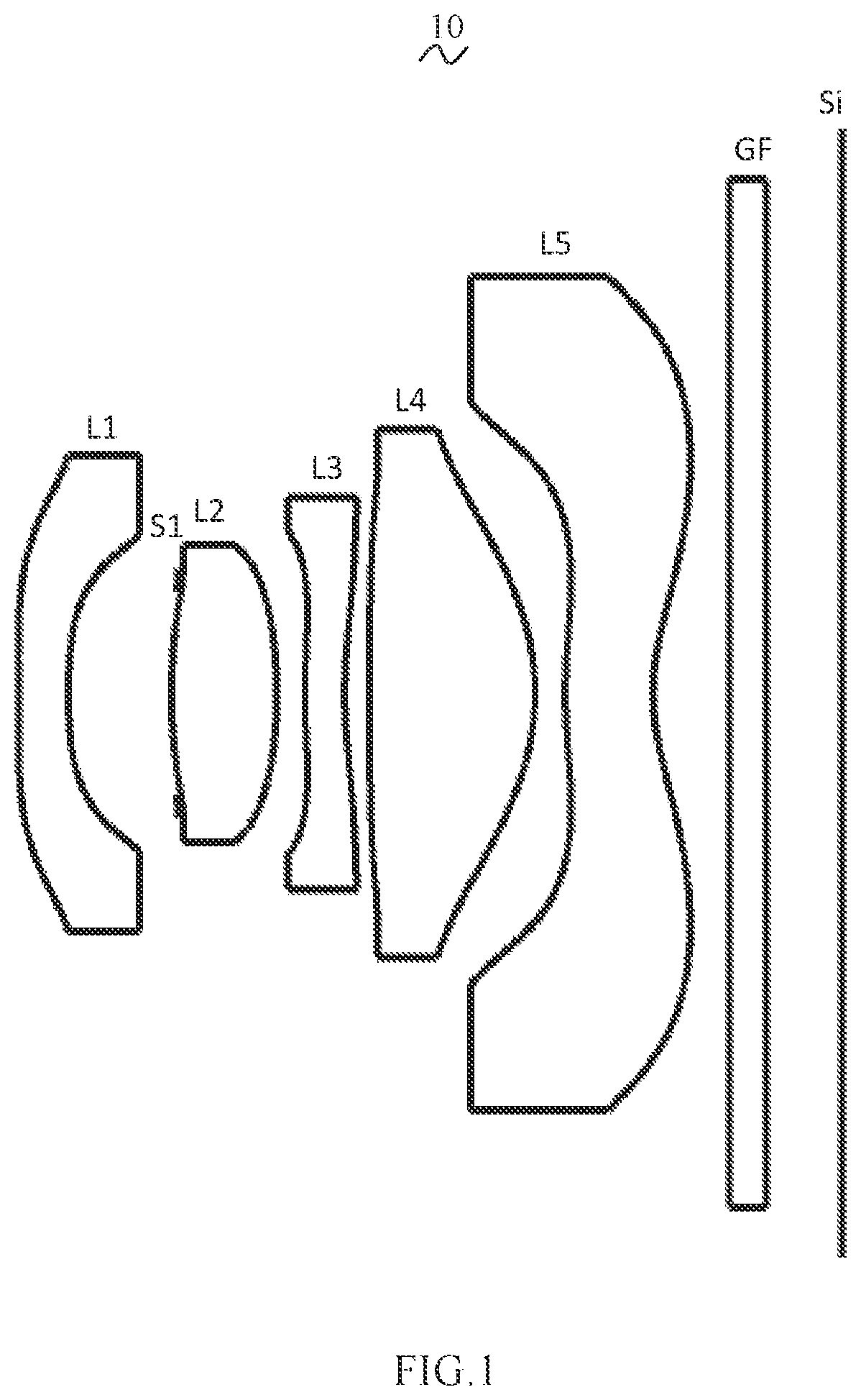
is a schematic diagram of a structure of a camera optical lens according to Embodiment 1 of the present disclosure;
is a schematic diagram of a longitudinal aberration of the camera optical lens shown in ;
is a schematic diagram of a lateral color of the camera optical lens shown in ;
is a schematic diagram of a field curvature and a distortion of the camera optical lens shown in ;
is a schematic diagram of a structure of a camera optical lens according to Embodiment 2;
is a schematic diagram of a longitudinal aberration of the camera optical lens shown in ;
is a schematic diagram of a lateral color of the camera optical lens shown in ;
is a schematic diagram of a field curvature and a distortion of the camera optical lens shown in ;
is a schematic diagram of a structure of a camera optical lens according to Embodiment 3;
is a schematic diagram of a longitudinal aberration of the camera optical lens shown in ;
is a schematic diagram of a lateral color of the camera optical lens shown in ; and
is a schematic diagram of a field curvature and a distortion of the camera optical lens shown in .
DESCRIPTION OF EMBODIMENTS
The present disclosure will hereinafter be described in detail with reference to several exemplary embodiments.
To make the technical problems to be solved, technical solutions and beneficial effects of the present disclosure more apparent, the present disclosure is described in further detail together with the figure and the embodiments. It should be understood the specific embodiments described hereby is only to explain the disclosure, not intended to limit the disclosure.
Embodiment 1
Referring to , the present disclosure provides a camera optical lens 10 in Embodiment 1. In , a left side is an object side, and a right side is an image side. The camera optical lens 10 mainly includes, from an object side to an image side, a first lens L 1 , an aperture S 1 , a second lens L 2 , a third lens L 3 , a fourth lens L 4 , and a fifth lens L 5 . A glass filter (GF) is arranged between the fifth lens L 5 and an image plane Si, and the glass filter (GF) can be a glass plate or can be an optical filter.
In the present embodiment, the first lens L 1 has a negative refractive power, the second lens L 2 has a positive refractive power, the third lens L 3 has a negative refractive power, the fourth lens L 4 has a positive refractive power, and the fifth lens L 5 has a negative refractive power.
In the present embodiment, the first lens L 1 is made of a plastic material, the second lens L 2 is made of a plastic material, the third lens L 3 is made of a plastic material, the fourth lens L 4 is made of a plastic material, and the fifth lens L 5 is made of a plastic material.
Here, a focal length of the camera optical lens 10 is defined as f, a focal length of the third lens L 3 is defined as f3, a curvature radius of an object side surface of the first lens L 1 is defined as R1, a curvature radius of an image side surface of the first lens L 1 is defined as R2, an on-axis thickness of the second lens L 2 is defined as d3, and an on-axis distance from the image side surface of the first lens L 1 to an object side surface of the second lens L 2 is defined as d2. The camera optical lens 10 should satisfy the following conditions: 0.50≤ d 2/ d 3≤2.00; (1) −4.00≤ R 1/ R 2≤−1.50; (2) and −8.00≤ f 3/ f≤− 4.00, (3)
The condition (1) specifies a ratio of the on-axis distance d2 from the first lens L 1 to the second lens L 2 to the on-axis thickness d3 of the second lens L 2 , which facilitates improving performance of the optical system.
The condition (2) specifies a shape of the first lens L 1 . This condition can alleviate deflection of light passing through the lens while effectively reducing aberrations.
The condition (3) specifies a ratio of the focal length f3 of the third lens L 3 to the focal length of the system. The condition facilitates to improving the imaging quality.
The focal length of the camera optical lens 10 is f, and a focal length of the fourth lens L 4 is defined as f4. The camera optical lens 10 further satisfies a condition of 0.60≤f4/f≤1.50, which specifies a ratio of the focal length f4 of the fourth lens L 4 to the focal length of the camera system lens 10 . This condition facilitates improving the performance of the optical system.
In the present embodiment, the first lens L 1 includes an object side surface being concave in a paraxial region and an image side surface being concave in the paraxial region.
Here, a focal length of the camera optical lens 10 is defined as f, and a focal length of the first lens L 1 is defined as f1. The camera optical lens 10 should satisfy a condition of −4.12≤f1/f≤−1.17, which specifies a ratio of the focal length f1 of the first lens L 1 to the focal length f of the system. When this condition is satisfied, the first lens L 1 can have an appropriate negative refractive power, so as to reduce aberrations of the system while facilitating the development towards ultra-thin and wide-angle lenses. As an example, −2.57≤f1/f≤−1.47.
A curvature radius of the object side surface of the first lens L 1 is defined as R1, and a curvature radius of the image side surface of the first lens L 1 is defined as R2. The camera optical lens 10 should satisfy a condition of 0.10≤(R1+R2)/(R1−R2)≤0.90, which can control a shape of the first lens L 1 , such that the first lens L 1 can effectively correct spherical aberrations of the system. As an example, 0.17≤(R1+R2)/(R1−R2)≤0.72.
An on-axis thickness of the first lens L 1 is defined as d1, and a total optical length from the object side surface of the first lens L 1 to an image plane of the camera optical lens along an optic axis is defined as TTL. The camera optical lens 10 should satisfy a condition of 0.03≤d1/TTL≤0.13. This condition can facilitate achieving ultra-thin lenses. As an example, 0.04≤d1/TTL≤0.10.
In the present embodiment, the second lens L 2 includes an object side surface being convex in a paraxial region, and an image side surface being convex in the paraxial region.
The focal length of the camera optical lens 10 is defined as f, and a focal length of the second lens L 2 is defined as f2. The camera optical lens 10 should satisfy a condition of 0.59≤f2/f≤1.97. By controlling the refractive power of the second lens L 2 in an appropriate range, the aberration of the optical system can be advantageously corrected. As an example, 0.95≤f2/f≤1.58.
A curvature radius of the object side surface of the second lens L 2 is defined as R3, and a curvature radius of the image side surface of the second lens L 2 is defined as R4. The camera optical lens 10 should satisfy a condition of −0.51≤(R3+R4)/(R3−R4)≤−0.01, which specifies a shape of the second lens L 2 . This can facilitate correction of an on-axis aberration with the development towards ultra-thin lenses. As an example, −0.32≤(R3+R4)/(R3−R4)≤−0.01.
An on-axis thickness of the second lens L 2 is defined as d3, and the total optical length from the object side surface of the first lens L 1 to an image plane of the camera optical lens 10 along an optic axis is defined as TTL. The camera optical lens 10 should satisfy a condition of 0.05≤d3/TTL≤0.25. This can facilitate achieving ultra-thin lenses. As an example, 0.07≤d3/TTL≤0.20.
In the present embodiment, the third lens L 3 includes an object side surface being convex in a paraxial region, and an image side surface being concave in the paraxial region.
A curvature radius of the object side surface of the third lens L 3 is defined as R5, and a curvature radius of the image side surface of the third lens L 3 is defined as R6. The camera optical lens 10 should satisfy a condition of 2.03≤(R5+R6)/(R5−R6)≤12.74. This can effectively control a shape of the third lens L 3 , thereby facilitating the shaping of the third lens L 3 . This condition can alleviate deflection of light passing through the lens while effectively reducing aberrations. As an example, 3.24≤(R5+R6)/(R5−R6)≤10.19.
An on-axis thickness of the third lens L 3 is defined as d5, and the total optical length from the object side surface of the first lens L 1 to an image plane of the camera optical lens 10 along an optic axis is defined as TTL. The camera optical lens 10 should satisfy a condition of 0.02≤d5/TTL≤0.07, which can achieve the ultra-thin lenses. As an example, 0.04≤d5/TTL≤0.06.
In the present embodiment, the fourth lens L 4 includes an object side surface being convex in a paraxial region, and an image side surface being convex in the paraxial region.
A curvature radius of the object side surface of the fourth lens L 4 is defined as R7, and a curvature radius of the image side surface of the fourth lens L 4 is defined as R8. The camera optical lens 10 should satisfy a condition of 0.44≤(R7+R8)/(R7−R8)≤1.38, which specifies a shape of the fourth lens L 4 . This can facilitate the correction of an off-axis aberration with the development towards ultra-thin and wide-angle lenses. As an example, 0.70≤(R7+R8)/(R7−R8)≤1.11.
An on-axis thickness of the fourth lens L 4 is defined as d7, and the total optical length from the object side surface of the first lens L 1 to an image plane of the camera optical lens 10 along an optic axis is defined as TTL. The camera optical lens 10 should satisfy a condition of 0.10≤d7/TTL≤0.31, which can achieve the ultra-thin lenses. As an example, 0.16≤d7/TTL≤0.25.
In the present embodiment, the fifth lens L 5 includes an object side surface being convex in a paraxial region, and an image side surface being concave in the paraxial region.
A focal length of the fifth lens L 5 is f5, and the focal length of the camera optical lens 10 is f. The camera optical lens 10 further satisfies a condition of −7.14≤f5/f≤−0.50. The limitations on the fifth lens L 5 can effectively make a light angle of the camera optical lens 10 gentle and reduce the tolerance sensitivity. As an example, −4.46≤f5/f≤−0.62.
A curvature radius of the object side surface of the fifth lens L 5 is defined as R9, and a curvature radius of the image side surface of the fifth lens L 5 is defined as R10. The camera optical lens 10 should satisfy a condition of 0.56≤(R9+R10)/(R9−R10)≤7.12, which specifies a shape of the fifth lens L 5 . This can facilitate the correction of an off-axis aberration with the development towards the ultra-thin and wide-angle lenses. As an example, 0.89≤(R9+R10)/(R9−R10)≤50.70.
An on-axis thickness of the fifth lens L 5 is defined as d9, and the total optical length from the object side surface of the first lens L 1 to an image plane of the camera optical lens 10 along an optic axis is defined as TTL. The camera optical lens 10 should satisfy a condition of 0.05≤d9/TTL≤0.16, which can achieve the ultra-thin lenses. As an example, 0.09≤d9/TTL≤0.13.
In the present embodiment, an image height of the camera optical lens 10 is IH. The camera optical lens 10 should satisfy a condition of TTL/IH≤1.85, which can achieve the ultra-thin lens.
In the present embodiment, a field of view (FOV) of the camera optical lens 10 is larger than or equal to 119°, so as to achieve a wide angle.
In the present embodiment, the focal length of the camera optical lens 10 is defined as f, and a combined focal length of the first lens L 1 and the second lens L 2 is defined as f12. The camera optical lens 10 should satisfy a condition of 0.89≤f12/f≤4.22, which eliminates the aberration and distortion of the camera optical lens 10 , suppresses the back focal length of the camera optical lens 10 , and maintains the miniaturization of the camera lens system group. As an example, 1.42≤f12/f≤3.37.
In addition, in the camera optical lens 10 provided by the present embodiment, the surface of each lens can be set as an aspherical surface, and it is easy for the aspherical surface to be made into a shape other than a spherical surface, to obtain more control variables for reducing aberrations, thereby reducing the number of required lenses. In this way, the total length of the camera optical lens 10 can be effectively reduced. In the present embodiment, both the object side surface and the image side surface of each lens are all aspherical surfaces.
It should be understood that, since the first lens L 1 , the second lens L 2 , the third lens L 3 , the fourth lens L 4 , and the fifth lens L 5 have the structure and satisfy the parameter relationship as described above, the camera optical lens 10 can distribute the refractive power, spacing and shape of each lens, and thus various aberrations are corrected.
Thus, the camera optical lens 10 can further satisfy design requirements for ultra-thin, wide-angle lenses having large apertures while achieving good optical performance.
The following examples will be used to describe the camera optical lens 10 of the present disclosure. The symbols recorded in each example will be described as follows. The focal length, on-axis distance, curvature radius, on-axis thickness, inflexion point position, and arrest point position are all in units of mm.
TTL: total optical length (total optical length from the object side surface of the first lens L 1 to the image plane Si of the camera optical lens along the optic axis) in mm.
In addition, an inflection point and/or an arrest point can be provided on at least one of the object side surface and the image side surface of each lens, in order to meet the requirements of high-quality imaging. The specific implementations are described below.
The design data of the camera optical lens 10 shown in is listed below.
Table 1 includes the curvature radius of the object side surface and the curvature radius R of the image side surface of the first lens L 1 to the fifth lens L 5 that constitute the camera optical lens 10 in the Embodiment 1 of the present disclosure, the on-axis thickness of each lens, the distance d between adjacent lenses, refractive index nd and abbe number vd. It should be noted that R and d are both in units of millimeter (mm).
TABLE 1
R d nd vd
S1 ∞ d0= 0.000
R1 −6.161 d1= 0.281 nd1 1.5444 v1 55.82
R2 2.562 d2= 0.589
R3 2.254 d3= 0.599 nd2 1.5444 v2 55.82
R4 −2.330 d4= 0.163
R5 2.710 d5= 0.226 nd3 1.6700 v3 19.39
R6 1.860 d6= 0.140
R7 23.307 d7= 0.947 nd4 1.5346 v4 55.69
R8 −1.019 d8= 0.173
R9 1.994 d9= 0.500 nd5 1.6700 v5 19.39
R10 0.856 d10= 0.439
R11 ∞ d11= 0.210 ndg 1.5168 vg 64.17
R12 ∞ d12= 0.429
In the above table, meanings of various symbols will be described as follows.
S1: aperture;
R: curvature radius of an optical surface, a central curvature radius of a lens;
R1: curvature radius of the object side surface of the first lens L 1 ;
R2: curvature radius of the image side surface of the first lens L 1 ;
R3: curvature radius of the object side surface of the second lens L 2 ;
R4: curvature radius of the image side surface of the second lens L 2 ;
R5: curvature radius of the object side surface of the third lens L 3 ;
R6: curvature radius of the image side surface of the third lens L 3 ;
R7: curvature radius of the object side surface of the fourth lens L 4 ;
R8: curvature radius of the image side surface of the fourth lens L 4 ;
R9: curvature radius of the object side surface of the fifth lens L 5 ;
R10: curvature radius of the image side surface of the fifth lens L 5 ;
R11: curvature radius of an object side surface of the optical filter GF;
R12: curvature radius of an image side surface of the optical filter GF;
d: on-axis thickness of a lens and an on-axis distance between lenses;
d0: on-axis distance from the aperture S 1 to the object side surface of the first lens L 1 ;
d1: on-axis thickness of the first lens L 1 ;
d2: on-axis distance from the image side surface of the first lens L 1 to the object side surface of the second lens L 2 ;
d3: on-axis thickness of the second lens L 2 ;
d4: on-axis distance from the image side surface of the second lens L 2 to the object side surface of the third lens L 3 ;
d5: on-axis thickness of the third lens L 3 ;
d6: on-axis distance from the image side surface of the third lens L 3 to the object side surface of the fourth lens L 4 ;
d7: on-axis thickness of the fourth lens L 4 ;
d8: on-axis distance from the image side surface of the fourth lens L 4 to the object side surface of the fifth lens L 5 ;
d9: on-axis thickness of the fifth lens L 5 ;
d10: on-axis distance from the image side surface of the fifth lens L 5 to the object side surface of the optical filter GF;
d11: on-axis thickness of the optical filter GF;
d12: on-axis distance from the image side surface of the optical filter GF to the image plane;
nd: refractive index of d line;
nd1: refractive index of d line of the first lens L 1 ;
nd2: refractive index of d line of the second lens L 2 ;
nd3: refractive index of d line of the third lens L 3 ;
nd4: refractive index of d line of the fourth lens L 4 ;
nd5: refractive index of d line of the fifth lens L 5 ;
ndg: refractive index of d line of the optical filter GF;
vd: abbe number;
v1: abbe number of the first lens L 1 ;
v2: abbe number of the second lens L 2 ;
v3: abbe number of the third lens L 3 ;
v4: abbe number of the fourth lens L 4 ;
v5: abbe number of the fifth lens L 5 ;
vg: abbe number of the optical filter GF.
Table 2 shows aspheric surface data of respective lens in the camera optical lens 10 according to Embodiment 1 of the present disclosure.
TABLE 2
Conic coefficient Aspherical surface coefficients
k A4 A6 A8 A10 A12
R1 −2.3329E+01 6.6984E−01 −1.0982E+00 1.8112E+00 −2.2210E+00 1.7052E+00
R2 8.0803E+00 8.4596E−01 5.9235E−01 −1.1974E+01 7.1692E+01 −2.2475E+02
R3 7.8655E−01 2.8493E−01 −1.1334E+01 2.4628E+02 −3.1773E+03 2.5213E+04
R4 6.7437E+00 −2.6633E−01 −1.9940E+00 4.2684E+01 −4.0235E+02 2.1772E+03
R5 −4.0387E+01 −6.0279E−01 2.3074E+00 −2.0373E+01 1.2144E+02 −4.4683E+02
R6 −3.6787E+01 2.0628E−01 −2.9925E+00 1.5289E+01 −4.8377E+01 9.9276E+01
R7 −9.9004E+01 1.2241E−01 −9.4114E−01 4.0587E+00 −1.0636E+01 1.8213E+01
R8 −1.0298E+00 −7.9302E−02 9.1156E−01 −3.3122E+00 7.5020E+00 −1.0637E+01
R9 −3.4789E+01 −1.7966E−01 −2.4913E−01 5.9526E−01 −5.6204E−01 1.1939E−01
R10 −4.6080E+00 −2.6034E−01 2.2029E−01 −1.3426E−01 5.2764E−02 −1.2357E−02
Conic coefficient Aspherical surface coefficients
k A14 A16 A18 A20
R1 −2.3329E+01 −5.2358E−01 −2.9414E−01 2.9824E−01 −7.1751E−02
R2 8.0803E+00 3.8215E+02 −2.5254E+02 −1.2232E+02 1.7438E+02
R3 7.8655E−01 −1.2481E+05 3.7516E+05 −6.2600E+05 4.4442E+05
R4 6.7437E+00 −7.1505E+03 1.4028E+04 −1.5112E+04 6.8670E+03
R5 −4.0387E+01 9.9806E+02 −1.3061E+03 8.9854E+02 −2.4052E+02
R6 −3.6787E+01 −1.2955E+02 1.0210E+02 −4.3499E+01 7.4995E+00
R7 −9.9004E+01 −2.0362E+01 1.4303E+01 −5.7519E+00 1.0139E+00
R8 −1.0298E+00 9.4324E+00 −5.0572E+00 1.4954E+00 −1.8713E−01
R9 −3.4789E+01 2.1251E−01 −2.1466E−01 8.5440E−02 −1.2888E−02
R10 −4.6080E+00 1.1109E−03 1.9178E−04 −5.9911E−05 4.6543E−06
In Table 2, k is a conic coefficient, and A4, A6, A8, A10, A12, A14, A16, A18 and A20 are aspheric surface coefficients.
IH: image height y =( x 2 /R )/[1+{1−( k+ 1)( x 2 /R 2 )} 1/2 ]+ A 4 x 4 +A 6 x 6 +A 8 x 8 +A 10 x 10 +A 12 x 12 +A 14 x 14 +A 16 x 16 +A 18 x 18 +A 20 x 20 (4)
In the present embodiment, an aspheric surface of each lens surface uses the aspheric surfaces represented by the above condition (4). However, the present disclosure is not limited to the aspherical polynomial form represented by the condition (4).
Table 3 and Table 4 show design data of inflexion points and arrest points of respective lens in the camera optical lens 10 of the present embodiment. P1R1 and P1R2 represent the object side surface and the image side surface of the first lens L 1 , respectively; P2R1 and P2R2 represent the object side surface and the image side surface of the second lens L 2 , respectively; P3R1 and P3R2 represent the object side surface and the image side surface of the third lens L 3 , respectively; P4R1 and P4R2 represent the object side surface and the image side surface of the fourth lens L 4 , respectively; and P5R1 and P5R2 represent the object side surface and the image side surface of the fifth lens L 5 , respectively. The data in the column “inflexion point position” indicates vertical distances from inflexion points arranged on each lens surface to the optic axis of the camera optical lens 10 . The data in the column “arrest point position” indicates vertical distances from arrest points arranged on each lens surface to the optic axis of the camera optical lens 10 .
TABLE 3
Number of Inflexion point Inflexion point Inflexion point
inflexion points position 1 position 2 position 3
P1R1 2 0.155 0.985
P1R2 1 0.715
P2R1 2 0.475 0.545
P2R2 1 0.715
P3R1 2 0.225 0.775
P3R2 2 0.355 0.805
P4R1 2 0.925 1.045
P4R2 2 0.895 1.245
P5R1 3 0.295 1.265 1.405
P5R2 2 0.455 1.975
TABLE 4
Number of arrest Arrest point position
points 1
P1R1 1 0.265
P1R2 0
P2R1 0
P2R2 0
P3R1 1 0.395
P3R2 0
P4R1 0
P4R2 0
P5R1 1 0.555
P5R2 1 1.125
Table 13 below includes various values of Embodiments 1, 2 and 3 and parameters which are specified in the above conditions.
As shown in Table 3, Embodiment 1 satisfies the various conditions.
and illustrate a longitudinal aberration and a lateral color of light with wavelengths of 650 nm, 610 nm, 555 nm, 510 nm, 470 nm and 435 nm after passing the camera optical lens 10 . illustrates a field curvature and a distortion of light with a wavelength of 555 nm after passing the camera optical lens 10 , in which a field curvature S is a field curvature in a sagittal direction and T is a field curvature in a tangential direction.
In the present embodiment, the entrance pupil diameter of the camera optical lens 10 is 0.832 mm. The image height is 2.62 mm. The field of view (FOV) along a diagonal direction is 119.40°. Thus, the camera optical lens 10 is an ultra-thin, large-aperture, wide-angle lens in which on-axis and off-axis aberrations are sufficiently corrected, thereby leading to better optical characteristics.
Embodiment 2
is a structural schematic diagram of the camera optical lens 20 in Embodiment 2. Embodiment 2 is basically the same as embodiment 1 and involves symbols having the same meanings as Embodiment 1, and the same portions will not be repeated. Only differences therebetween will be described in the following.
Table 5 and Table 6 show design data of a camera optical lens 20 in Embodiment 2 of the present disclosure.
TABLE 5
R d nd vd
S1 ∞ d0= 0.000
R1 −9.368 d1= 0.416 nd1 1.5444 v1 55.82
R2 2.348 d2= 0.437
R3 2.069 d3= 0.794 nd2 1.5444 v2 55.82
R4 −3.475 d4= 0.116
R5 2.179 d5= 0.223 nd3 1.6700 v3 19.39
R6 1.720 d6= 0.091
R7 10.752 d7= 0.986 nd4 1.5346 v4 55.69
R8 −0.687 d8= 0.110
R9 16.091 d9= 0.520 nd5 1.6700 v5 19.39
R10 0.896 d10= 0.439
R11 ∞ d11= 0.210 ndg 1.5168 vg 64.17
R12 ∞ d12= 0.447
Table 6 shows aspheric surface data of respective lenses in the camera optical lens 20 according to Embodiment 2 of the present disclosure.
TABLE 6
Conic coefficient Aspherical surface coefficients
k A4 A6 A8 A10 A12
R1 −2.7925E+01 4.0226E−01 −4.4216E−01 4.9160E−01 −4.0008E−01 2.1159E−01
R2 5.8826E+00 9.1132E−01 −2.8174E+00 1.3180E+01 1.2123E+01 −4.5917E+02
R3 1.7478E+00 −2.9930E−01 1.6113E+01 −3.7306E+02 4.9082E+03 −3.9458E+04
R4 1.1856E+01 −6.8109E−01 2.6665E+00 −1.6088E+01 6.6643E+01 −1.7382E+02
R5 −5.9233E+01 −2.5422E−01 −5.9291E+00 7.7623E+01 −5.6973E+02 2.5014E+03
R6 −4.4351E+01 −5.2375E−01 5.0166E+00 −3.3313E+01 1.2472E+02 −2.8629E+02
R7 −9.8425E+01 −7.0183E−01 6.1274E+00 −3.0592E+01 9.4096E+01 −1.8535E+02
R8 −1.2740E+00 8.1094E−01 −2.7065E+00 7.3521E+00 −1.5387E+01 2.2538E+01
R9 9.9018E+01 1.8507E−01 −1.3063E+00 3.2253E+00 −6.0804E+00 7.9035E+00
R10 −6.5467E+00 −5.0068E−02 −1.1581E−01 1.7541E−01 −1.3257E−01 6.2634E−02
Conic coefficient Aspherical surface coefficients
k A14 A16 A18 A20
R1 −2.7925E+01 −5.8972E−02 −5.8478E−03 8.8847E−03 −1.7550E−03
R2 5.8826E+00 2.3436E+03 −5.7090E+03 6.9860E+03 −3.4644E+03
R3 1.7478E+00 1.9732E+05 −5.9977E+05 1.0155E+06 −7.3552E+05
R4 1.1856E+01 2.4949E+02 −1.3306E+02 −7.9127E+01 8.9099E+01
R5 −5.9233E+01 −6.7614E+03 1.1025E+04 −9.9425E+03 3.7989E+03
R6 −4.4351E+01 4.0846E+02 −3.4974E+02 1.6281E+02 −3.1247E+01
R7 −9.8425E+01 2.3234E+02 −1.7795E+02 7.5548E+01 −1.3574E+01
R8 −1.2740E+00 −2.1688E+01 1.2862E+01 −4.2236E+00 5.8600E−01
R9 9.9018E+01 −6.6075E+00 3.3186E+00 −8.9987E−01 1.0073E−01
R10 −6.5467E+00 −1.9365E−02 3.8120E−03 −4.3332E−04 2.1659E−05
Table 7 and Table 8 show design data of inflexion points and arrest points of respective lens in the camera optical lens 20 .
TABLE 7
Number of Inflexion Inflexion Inflexion Inflexion
inflexion point point point point
points position 1 position 2 position 3 position 4
P1R1 2 0.155 1.115
P1R2 1 0.695
P2R1 1 0.495
P2R2 0
P3R1 1 0.215
P3R2 2 0.305 0.895
P4R1 4 0.125 0.315 0.415 0.805
P4R2 1 1.035
P5R1 2 0.345 1.205
P5R2 2 0.505 1.945
TABLE 8
Number of Arrest point Arrest point
arrest points position 1 position 2
P1R1 1 0.275
P1R2 0
P2R1 0
P2R2 0
P3R1 1 0.385
P3R2 1 0.555
P4R1 2 0.505 0.985
P4R2 1 1.215
P5R1 1 0.495
P5R2 1 1.175
Table 13 includes various values of Embodiment 2 and values corresponding to parameters which are specified in the above conditions. Obviously, the camera optical lens of the present embodiment satisfies the various conditions.
and illustrate a longitudinal aberration and a lateral color of light with wavelengths of 650 nm, 610 nm, 555 nm, 510 nm, 470 nm and 435 after passing the camera optical lens 20 . illustrates a field curvature and a distortion of light with a wavelength of 555 nm after passing the camera optical lens 20 , in which a field curvature S is a field curvature in a sagittal direction and T is a field curvature in a tangential direction.
In the present embodiment, the entrance pupil diameter of the camera optical lens 20 is 0.852 mm. The image height is 2.62 mm. The FOV along a diagonal direction is 119.00°. Thus, the camera optical lens 20 is an ultra-thin, large-aperture, wide-angle lens in which on-axis and off-axis aberrations sufficiently are corrected, thereby leading to better optical characteristics.
Embodiment 3
is a structural schematic diagram of the camera optical lens 30 in Embodiment 3. Embodiment 3 is basically the same as Embodiment 1 and involves symbols having the same meanings as Embodiment 1, and the same portions will not be repeated. Only differences therebetween will be described in the following.
Table 9 and Table 10 show design data of a camera optical lens 30 in Embodiment 3 of the present disclosure.
TABLE 9
R d nd vd
S1 ∞ d0= −1.092
R1 −5.428 d1= 0.258 nd1 1.5444 v1 55.82
R2 3.571 d2= 0.797
R3 2.032 d3= 0.433 nd2 1.5444 v2 55.82
R4 −2.926 d4= 0.264
R5 3.354 d5= 0.223 nd3 1.6700 v3 19.39
R6 2.026 d6= 0.111
R7 37.038 d7= 0.970 nd4 1.5346 v4 55.69
R8 −1.524 d8= 0.168
R9 1.164 d9= 0.523 nd5 1.6700 v5 19.39
R10 0.759 d10= 0.439
R11 ∞ d11= 0.210 ndg 1.5168 vg 64.17
R12 ∞ d12= 0.412
Table 10 shows aspheric surface data of respective lenses in the camera optical lens 30 according to Embodiment 3 of the present disclosure.
TABLE 10
Conic coefficient Aspherical surface coefficients
k A4 A6 A8 A10 A12
R1 −5.7262E+01 5.9380E−01 −9.7094E−01 1.6599E+00 −2.2312E+00 2.1412E+00
R2 6.8322E+00 7.9790E−01 −4.4503E−01 −1.7872E+00 1.5015E+01 −4.7533E+01
R3 2.9123E−01 −1.1688E−03 7.8451E−01 −1.9402E+01 2.0678E+02 −1.3787E+03
R4 6.4270E+00 −1.8898E−01 5.4269E−01 −8.6615E+00 7.3032E+01 −3.9839E+02
R5 −6.2387E+01 −5.4358E−01 2.3186E+00 −1.7228E+01 8.3909E+01 −2.9143E+02
R6 −6.2609E+01 2.1512E−02 −7.4569E−01 3.1364E+00 −1.0149E+01 2.3653E+01
R7 9.9006E+01 −3.3139E−01 1.6748E+00 −5.5120E+00 1.3898E+01 −2.3549E+01
R8 −2.3295E−01 −1.2788E+00 5.9582E+00 −1.7452E+01 3.4071E+01 −4.4096E+01
R9 −5.9629E+00 −1.3828E+00 4.4351E+00 −1.0644E+01 1.7021E+01 −1.8015E+01
R10 −6.3596E+00 −1.6134E−01 7.1024E−02 −1.2554E−02 −5.1098E−03 3.0562E−03
Conic coefficient Aspherical surface coefficients
k A14 A16 A18 A20
R1 −5.7262E+01 −1.3552E+00 5.0048E−01 −8.9775E−02 4.7294E−03
R2 6.8322E+00 8.5976E+01 −8.3063E+01 3.2190E+01 −3.1878E−01
R3 2.9123E−01 5.8504E+03 −1.5401E+04 2.2744E+04 −1.4358E+04
R4 6.4270E+00 1.3470E+03 −2.7841E+03 3.2231E+03 −1.6193E+03
R5 −6.2387E+01 6.8914E+02 −1.0380E+03 8.8947E+02 −3.2698E+02
R6 −6.2609E+01 −3.4966E+01 2.9809E+01 −1.2497E+01 1.6854E+00
R7 9.9006E+01 2.5269E+01 −1.6484E+01 5.9780E+00 −9.2524E−01
R8 −2.3295E−01 3.7338E+01 −1.9787E+01 5.9268E+00 −7.6300E−01
R9 −5.9629E+00 1.2421E+01 −5.3589E+00 1.3116E+00 −1.3851E−01
R10 −6.3596E+00 −5.4378E−04 8.3972E−06 6.1878E−06 −2.6239E−07
Table 11 and Table 12 show design data of inflexion points and arrest points of respective lens in the camera optical lens 30 .
TABLE 11
Number of Inflexion point Inflexion point Inflexion point
inflexion points position 1 position 2 position 3
P1R1 2 0.165 1.055
P1R2 1 0.825
P2R1 1 0.485
P2R2 0
P3R1 1 0.215
P3R2 3 0.345 0.775 0.925
P4R1 2 0.095 0.425
P4R2 1 0.865
P5R1 2 0.255 1.285
P5R2 2 0.435 1.965
TABLE 12
Number of Arrest point Arrest point
arrest points position 1 position 2
P1R1 1 0.295
P1R2 0
P2R1 0
P2R2 0
P3R1 1 0.375
P3R2 0
P4R1 2 0.155 0.575
P4R2 0
P5R1 1 0.545
P5R2 1 1.105
Table 13 below includes various values of Embodiment 3 and parameters which are specified in the above conditions. Obviously, the camera optical lens of the present embodiment satisfies the various conditions.
and illustrate a longitudinal aberration and a lateral color of light with wavelengths of 650 nm, 610 nm, 555 nm, 510 nm, 470 nm and 435 nm after passing the camera optical lens 30 . illustrates a field curvature and a distortion of light with a wavelength of 555 nm after passing the camera optical lens 30 , in which a field curvature S is a field curvature in a sagittal direction and T is a field curvature in a tangential direction.
In the present embodiment, the entrance pupil diameter of the camera optical lens 30 is 0.850 mm. The image height is 2.62 mm. The FOV along a diagonal direction is 119.00°. Thus, the camera optical lens 30 is an ultra-thin, large-aperture, wide-angle lens in which the on-axis and off-axis aberrations are sufficiently corrected, thereby leading to better optical characteristics.
Table 13 below includes various values of Embodiment 1, Embodiment 2, and Embodiment 3 and parameters which are specified in the above conditions.
TABLE 13
Parameters and Conditions Embodiment 1 Embodiment 2 Embodiment 3
d2/d3 0.98 0.55 1.84
f3/f −5.28 −7.90 −4.28
R1/R2 −2.40 −3.99 −1.52
f 1.860 1.905 1.897
f1 −3.276 −3.395 −3.904
f2 2.199 2.501 2.266
f3 −9.820 −15.046 −8.119
f4 1.846 1.241 2.753
f5 −2.695 −1.422 −6.768
f12 3.755 5.355 3.377
Fno 2.24 2.24 2.23
In Table 13, Fno is an F number of the camera optical lens.
The above are only the embodiments of the present disclosure. It should be understand that those of ordinary skill in the art can make improvements without departing from the inventive concept of the present disclosure, and these improvement all belong to the scope of the present disclosure.
Figures (9)
Citations
This patent cites (1)
- US20210033823