Motor and Torque Converter Clutch Control Strategy for Electric Drive Unit Having Motor-driven Torque Converter
Abstract
A method for controlling an electric drive unit (EDU) having a motor-driven torque converter includes receiving a request signal indicative of a requested output torque of the EDU, and operating the motor at a target motor speed using the requested output torque. The target motor speed minimizes system losses while achieving the requested output torque. When the requested output torque remains below a calibrated threshold and a turbine speed is less than a corner speed of the motor, a torque converter clutch (TCC) transitions to or remains in a locked state. The controller commands the TCC to transition to an unlocked state to reach the target motor speed, thereby selectively enabling torque multiplication. A powertrain system includes a driven load and the EDU. A computer readable storage medium may include executable instructions for performing the method.
Claims (20)
1 . A method for controlling an electric drive unit (EDU) of a motor vehicle, the EDU having a torque converter connected to an electric traction motor such that a pump of the torque converter is driven by an output member of the electric traction motor, the method comprising: receiving, via a controller, a request signal indicative of a requested output torque of the EDU; accelerating the electric traction motor to a target motor speed at a calibrated speed profile, the calibrated speed profile corresponding to a predetermined vehicle acceleration rate, wherein the calibrated speed profile and the target motor speed are configured to minimize total system losses of the EDU while achieving the requested output torque; when the predetermined vehicle acceleration rate remains below a calibrated acceleration threshold and a turbine speed of a turbine of the torque converter is less than a corner speed of the electric traction motor, commanding a torque converter clutch (TCC) of the torque converter to transition to or remain in a locked state; and commanding the TCC to transition to an unlocked state from the locked state to reach the target motor speed, thereby selectively enabling multiplication of an input torque from the electric traction motor when operating at the target motor speed, wherein the target motor speed corresponds to an actual output torque that is achievable by the torque converter when the TCC is in the unlocked state being equal to an actual output torque achievable by the torque converter when the TCC is in the locked state.
9 . A powertrain system for a motor vehicle, comprising: a driven load; and an electric drive unit (EDU) coupled to the driven load, the EDU comprising: an electric traction motor operatively connected to the driven load; a torque converter having a pump and a turbine, wherein the pump is connected to and driven by the electric traction motor; and a controller in communication with the electric traction motor and the torque converter, wherein the controller is configured to: receive a request signal indicative of a requested output torque of the EDU; accelerate the electric traction motor to a target motor speed at a calibrated speed profile, the calibrated speed profile corresponding to a predetermined vehicle acceleration rate, wherein the target motor speed and the calibrated speed profile are configured to minimize total system losses of the EDU while achieving the requested output torque; command a torque converter clutch (TCC) of the torque converter to transition to or remain in a locked state when the predetermined vehicle acceleration rate remains below a calibrated acceleration threshold and a turbine speed of the turbine of the torque converter is less than a corner speed of the electric traction motor; and command the TCC to transition to an unlocked state to reach the target motor speed, thereby selectively enabling multiplication of an input torque from the electric traction motor when operating at the target motor speed, wherein the calibrated acceleration threshold is a predetermined vehicle acceleration rate at which an output torque achievable by the torque converter when the TCC is in the unlocked state equals an output torque achievable by the torque converter when the TCC is in the locked state.
17 . A computer-readable storage medium on which instructions are recorded for controlling an electric drive unit (EDU) having a torque converter connected to an electric traction motor, such that a pump of the torque converter is driven by an output member of the electric traction motor, wherein execution of the instructions by a processor causes the processor to: receive a request signal indicative of a requested output torque of the EDU; accelerate the electric traction motor to a predetermined target motor speed at a predetermined speed profile, the predetermined speed profile corresponding to a predetermined vehicle acceleration rate, wherein the predetermined target speed and the calibrated speed profile are configured to minimize total system losses of the EDU while achieving the requested output torque; command a torque converter clutch (TCC) of the torque converter to transition to or remain in a locked state when the predetermined vehicle acceleration rate remains below a calibrated acceleration threshold and a turbine speed of the torque converter is less than a corner speed of the electric traction motor; and command the TCC to transition to an unlocked state to reach the target motor speed, thereby selectively enabling multiplication of an input torque from the electric traction motor when operating at the target motor speed, wherein the calibrated acceleration threshold is a predetermined vehicle acceleration rate at which an output torque achievable by the torque converter when the TCC is in the unlocked state equals an output torque achievable by the torque converter when the TCC is in the locked state.
Show 17 dependent claims
2 . The method of claim 1 , wherein receiving the request signal includes receiving a pedal position signal indicative of a percentage of apply force or travel of an accelerator pedal of the motor vehicle.
3 . The method of claim 2 , further comprising extracting the target motor speed, via the controller, from a lookup table indexed by the pedal position.
4 . The method of claim 1 , further comprising: when the TCC is in the locked state, applying a hysteresis band below a predetermined speed of the electric traction motor to prevent the TCC from transitioning from the locked state to the unlocked state while the electric traction motor operates within the hysteresis band.
5 . The method of claim 1 , the method further comprising: determining if the motor vehicle is stationary or moving; and ramping a rotary speed of the pump of the torque converter to the target motor speed at a first rate or a second rate depending on whether the motor vehicle is stationary or moving, respectively.
6 . The method of claim 5 , further comprising: when the motor vehicle is stationary, ramping the rotary speed of the pump of the torque converter to the target motor speed at the first rate, wherein the first rate is a calibrated maximum acceleration rate of the electric traction motor.
7 . The method of claim 5 , further comprising: when the motor vehicle is moving, ramping the rotary speed of the pump of the torque converter to the target motor speed at the second rate, wherein the second rate is less than the first rate and is limited by an available battery power level of a propulsion battery connected to the electric traction motor.
8 . The method of claim 1 , further comprising: maintaining the TCC in the locked state when the electric traction motor operates below a peak motor torque; and unlocking the TCC when the requested output torque exceeds the peak motor torque.
10 . The powertrain system of claim 9 , further comprising an accelerator pedal, wherein the request signal includes a pedal position signal indicative of a percentage of apply force or travel of the accelerator pedal.
11 . The powertrain system of claim 10 , wherein the controller is configured to extract the target motor speed from a lookup table indexed by a pedal position of the accelerator pedal.
12 . The powertrain system of claim 9 , wherein the controller is configured to prevent the TCC from transitioning from the locked state to the unlocked state while the electric traction motor operates within a hysteresis band.
13 . The powertrain system of claim 9 , wherein the driven load includes one or more road wheels of the motor vehicle, and the EDU is used aboard the motor vehicle to power a vehicle propulsion function thereof.
14 . The powertrain system of claim 13 , wherein the controller is configured to determine if the motor vehicle is stationary or moving, and to thereafter ramp a rotary speed of the pump of the torque converter to the target motor speed at a first rate or a second rate depending on whether the motor vehicle is stationary or moving, respectively.
15 . The powertrain system of claim 14 , wherein when the motor vehicle is stationary, the controller is configured to ramp the rotary speed of the pump of the torque converter to the target motor speed at the first rate, and wherein the first rate is a calibrated maximum acceleration rate of the electric traction motor.
16 . The powertrain system of claim 14 , wherein when the motor vehicle is moving, the controller is configured to ramp the rotary speed of the pump of the torque converter to the target motor speed at the second rate, wherein the second rate is less than the first rate and is limited by an available battery power level of a propulsion battery connected to the electric traction motor.
18 . The computer-readable storage medium of claim 17 , wherein the execution of the instructions causes the processor to maintain the TCC in the locked state when the electric traction motor operates below a peak motor torque, and to unlock the TCC only when the requested output torque exceeds the peak motor torque.
19 . The computer-readable storage medium of claim 17 , wherein the execution of the instructions causes the processor to prevent the TCC from transitioning from the locked state to the unlocked state while the electric traction motor operates within a hysteresis band of the electric traction motor.
20 . The computer-readable storage medium of claim 17 , wherein the EDU is part of a motor vehicle, and wherein the execution of the instructions causes the processor to determine if the motor vehicle is stationary or moving, and to thereafter ramp a rotary speed of the pump of the torque converter to the target motor speed at a first rate or a second rate depending on whether the motor vehicle is stationary or moving, respectively.
Full Description
Show full text →
CROSS-REFERENCE TO RELATED APPLICATIONS
This application claims priority to and the benefit of Chinese Patent Application No. 202111444464.8, which was filed on Nov. 30, 2021, and which is hereby incorporated by reference in its entirety.
INTRODUCTION
Powertrain systems are equipped with one or more torque actuators. When the powertrain system is configured for use aboard a mobile system, for instance, output torque provided by the various torque actuators is used for locomotion. In such a case, the individual torque actuators act as a collective set of propulsion actuators. Electric vehicles, robots, and other mobile platforms may include an electric drive unit (EDU) in which motor output torque from one or more electric traction motors is directed to a set of road wheels. Stationary systems may use a similar EDU for other beneficial purposes, e.g., to rotate a drive belt when powering a driven load or when generating electricity.
Electric traction motors, electric generators, and other rotary electric machines are capable of producing relatively high levels of output torque at low rotary speeds, e.g., relative to low-speed torque generating capabilities of an internal combustion engine. However, the relative speed-torque performance advantages of electric machines are substantially lessened at higher rotary speeds. The output power capability of an electric traction motor is equal to the product of its output torque and speed. Traditionally, therefore, electric traction motors have been sized to provide sufficient output power capability for a particular application. As an alternative solution, an electrically-powered hydrodynamic torque converter may be used to boost the torque and power output of an electric traction motor, thereby avoiding the need for oversizing the motor.
SUMMARY
The present disclosure pertains to the real-time control of a powertrain system of a motor vehicle. The powertrain system includes an electric traction motor (“motor”) and a hydrodynamic torque converter assembly (“torque converter”). The torque converter includes an input member in the form of an impeller, also referred to hereinafter as a pump, which in the present implementations is connected to a rotor shaft or other output member of the motor such that the torque converter is “motor-driven” within the scope of the disclosure. The torque converter also includes a stator, an output member in the form of a transmission-connected turbine, and a torque converter clutch (TCC). The TCC is operable for selectively locking the pump to the turbine to allow the pump and turbine to rotate together in unison, i.e., at the same speed/without slip. The torque converter includes an output member such as a turbine shaft that drivingly connects to a rotatable input member of a transmission to thereby transfer torque from the motor to the transmission.
As appreciated by those skilled in the art, torque converter assemblies are typically equipped with a TCC acting as an internal lockup clutch mechanism. The TCC is selectively applied to rigidly connect one rotating member to another when the respective rotational speeds are nearly equal. Methods described below are used to regulate a rotary speed (“motor speed”) of the electric traction motor, as well as a locked/unlocked apply state of the TCC, with a powertrain control module or other system controller performing the method in a coordinated motor/pump acceleration profile-based manner that minimizes overall system losses.
An aspect of the disclosure includes a method for controlling an electric drive unit (EDU) of a motor vehicle. The EDU includes a torque converter connected to an electric traction motor, such that a pump of the torque converter is driven by an output member of the electric traction motor. The method according to an embodiment includes receiving, via a controller, a request signal indicative of a requested output torque of the EDU The method also includes accelerating the motor to a target motor speed at a calibrated speed profile, with the calibrated speed profile corresponding to a predetermined vehicle acceleration rate. The calibrated speed profile and the target motor speed are configured to minimize total system losses of the EDU while achieving the requested output torque.
When the predetermined vehicle acceleration rate remains below a calibrated acceleration threshold and a turbine speed of a turbine of the torque converter is less than a corner speed of the electric traction motor, the method includes commanding the TCC to transition to or remain in a locked state. The method also includes commanding the TCC to transition to an unlocked state to reach the target motor speed, thereby selectively enabling multiplication of an input torque from the electric traction motor when operating at the target motor speed. As appreciated in the art, the term “corner speed” as used herein is the particular rotational speed at which the motor reaches its maximum power.
The target motor speed used herein may correspond to an actual output torque that is achievable by the torque converter when the TCC is in the unlocked state being equal to an actual output torque achievable by the torque converter when the TCC is in a locked state.
In some embodiments, the disclosed motor vehicle includes an accelerator pedal having, a measurable pedal position, in which case receiving the request signal includes receiving a pedal position signal indicative of a percentage of apply force or travel of the accelerator pedal. The method may include extracting the target motor speed from a lookup table indexed by the pedal position or apply force.
When the TCC is in the locked state, the method may further include applying a vehicle acceleration-based hysteresis band that is operational below a predetermined rotational speed of the electric traction motor. This action is performed to prevent the TCC from transitioning from the locked state to the unlocked state while the motor operates to produce vehicle acceleration levels within the hysteresis band.
The EDU in some implementations may be used to power a vehicle propulsion function. In such a representative use case, the method may further include determining if the motor vehicle is stationary or moving, and then ramping a rotary speed of the torque converter pump to the target motor speed at a first rate or a second rate depending on whether the motor vehicle is stationary or moving, respectively.
When the motor vehicle is stationary, the method may include ramping the rotary speed of the pump to the target motor speed at the first rate, with the first rate being calibrated maximum acceleration rate of the electric traction motor. When the motor vehicle is moving, the method may include ramping the rotary speed of the pump to the target motor speed at the second rate. The second rate, which is less than the first rate, is limited by an available battery power level of a propulsion battery connected to the electric traction motor.
In another aspect of the disclosure, the method may include maintaining the TCC in the locked state when the electric traction motor operates below a peak motor torque, and unlocking the TCC when the requested output torque exceeds the peak motor torque.
Also disclosed herein is a powertrain system having an EDU and a driven load. The EDU includes an electric traction motor operatively connected to the driven load, and a torque converter having a pump and a turbine, with the pump being connected to and driven by the motor. A controller is in communication with the motor and the torque converter. The controller is configured to execute the above-summarized method.
Additionally, a computer-readable storage medium is disclosed on which instructions are recorded for controlling the EDU. Execution of the instructions by a processor causes the processor to receive a request signal indicative of a requested output torque of the EDU, and to accelerate the motor to a target motor speed for a predetermined vehicle acceleration rate. Execution of the instructions also causes the processor to command the TCC to transition to or remain in a locked state when the predetermined vehicle acceleration rate remains below a calibrated acceleration threshold and a turbine speed of the torque converter is less than a corner speed of the electric traction motor. The processor also commands the TCC to transition to an unlocked state upon reaching the target motor speed, thereby selectively enabling multiplication of an input torque from the electric traction motor when operating above the target motor speed.
The above features and advantages, and other features and attendant advantages of this disclosure, will be readily apparent from the following detailed description of illustrative examples and modes for carrying out the present disclosure when taken in connection with the accompanying drawings and the appended claims. Moreover, this disclosure expressly includes combinations and sub-combinations of the elements and features presented above and below.
BRIEF DESCRIPTION OF THE DRAWINGS
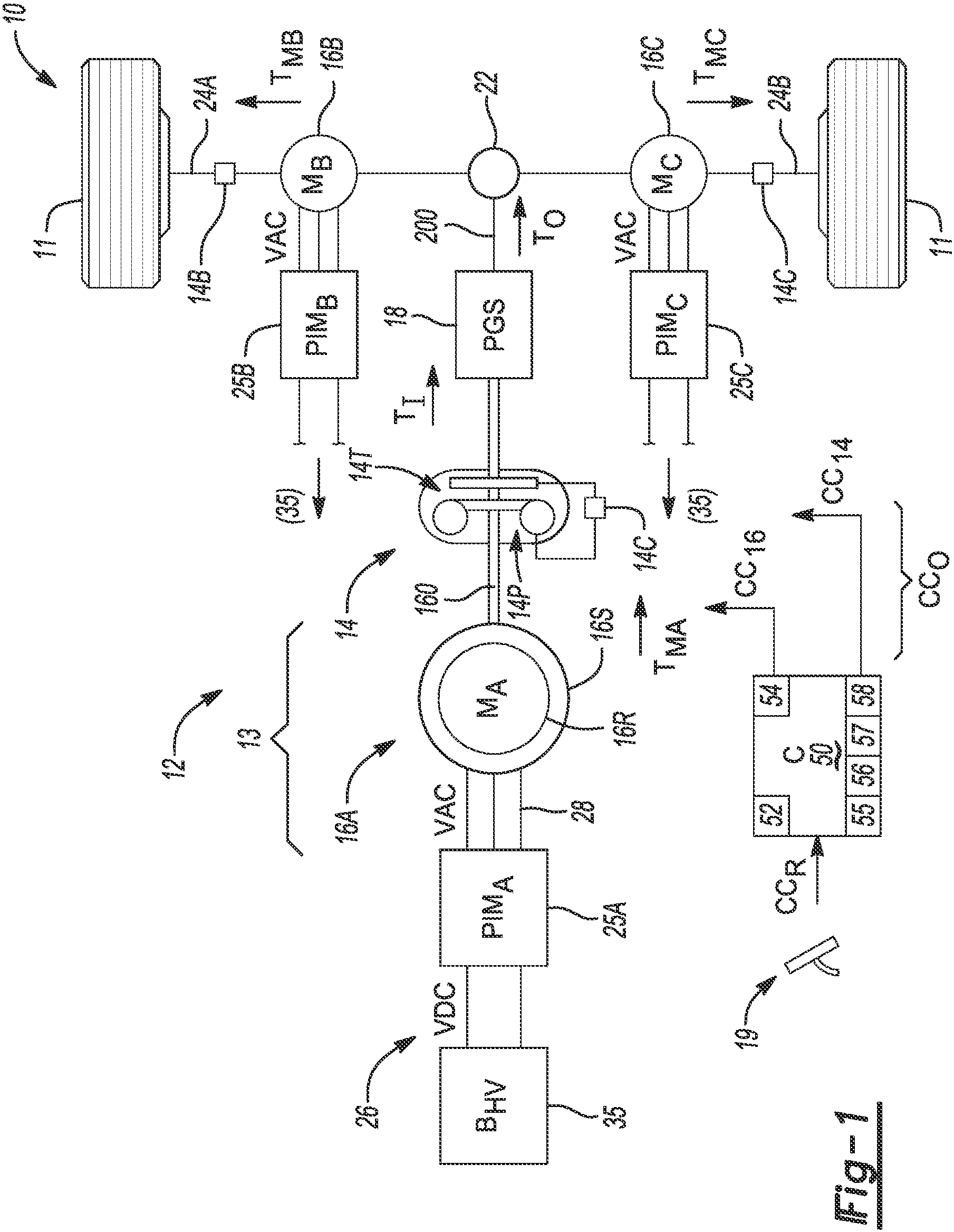
is a schematic illustration of a representative electrified powertrain system having a motor-driven torque converter and an electronic controller configured to regulate a rotary speed of the motor and an ON/OFF apply state of a torque converter clutch of the torque converter.
A is a partial section view of a representative electric drive unit (EDU) usable as part of the powertrain system shown in .
is a time plot of representative motor ramp-up speeds for control of the traction motor depicted in , with time in seconds depicted on the horizontal axis and motor speed in revolutions per minute (RPM) depicted on the vertical axis.
is a time plot of representative motor and turbine speeds, with time in seconds depicted on the horizontal axis and motor speed in RPM depicted on the vertical axis.
is a flow chart describing an embodiment of the present method.
is a time plot of representative motor and turbine torques and battery power for control of the powertrain system depicted in , with time in seconds depicted on the horizontal axis, and battery power in kilowatts (kW) and torque in Newton-meters (Nm) depicted on the vertical axis.
is a comparative plot of representative motor speeds, with time in seconds depicted on the horizontal axis and motor speed in RPM depicted on the vertical axis.
DETAILED DESCRIPTION
The present disclosure is susceptible of embodiment in many different forms. Representative examples of the disclosure are shown in the drawings and described herein in detail as non-limiting examples of the disclosed principles. To that end, elements and limitations described in the Abstract, Introduction, Summary, and Detailed Description sections, but not explicitly set forth in the claims, should not be incorporated into the claims, singly or collectively, by implication, inference, or otherwise.
For purposes of the present description, unless specifically disclaimed, use of the singular includes the plural and vice versa, the terms “and” and “or” shall be both conjunctive and disjunctive, “any” and “all” shall both mean “any and all”, and the words “including”, “containing”, “comprising”, “having”, and the like shall mean “including without limitation”. Moreover, words of approximation such as “about”, “almost”, “substantially”, “generally”, “approximately”, etc., may be used herein in the sense of “at, near, or nearly at”, or “within 0-5% of”, or “within acceptable manufacturing tolerances”, or logical combinations thereof.
Referring to the drawings, wherein like reference numbers refer to like features throughout the several views, and beginning with , a motor vehicle 10 includes a powertrain system 12 . The powertrain system 12 in the depicted representative configuration and similar configurations may be used in other types of systems, including but not limited to mobile platforms, robots, or stationary powerplants, and therefore the embodiment of is intended to be illustrative of just one possible beneficial application. In the depicted exemplary embodiment, the motor vehicle 10 includes one or more driven/powered road wheels 11 in rolling contact with a road surface (not shown). The actual number of road wheels 11 used on a given construction of the motor vehicle 10 may vary, with as few as one road wheel 11 being possible in the context of, e.g., a motorcycle, scooter, trike, or electric bike (“e-bike”), and with more than the illustrated number of road wheels 11 being possible in other configurations, such as but not limited to four-wheel drive or all-wheel drive vehicles, trucks, etc.
As described in detail herein, the powertrain system 12 includes an electronic controller (C) 50 , e.g., a powertrain control system. The controller 50 automatically regulates operation of the powertrain system 12 , and in particular that of an electric drive unit (EDU) 13 thereof. The EDU 13 , an example embodiment of which is depicted in A , in turn includes a hydrodynamic torque converter 14 , a pump 14 P of which in turn is driven as an input of the torque converter 14 via an electric traction motor (M A ) 16 A, with the latter being operable by converting stored electrical power into rotational mechanical torque as appreciated in the art. That is, an output member 160 of the motor 16 A, such as a rotor shaft, is drivingly connected with the torque converter 14 , with generated rotation of a rotor 16 R, of the motor 16 A ultimately causing the rotation of the pump 14 P. Fluidic coupling of the pump 14 P with an oppositely disposed turbine 14 T of the torque converter 14 , through an intervening stator 14 S (see A ), ultimately generates a variable input torque (arrow T I ) to a transmission (PGS) 18 , with “PCS” in this instance referring to a planetary gear set or another suitable torque transfer mechanism. Output torque (arrow T O ) from the transmission 18 is then transmitted via an output shaft 200 of the transmission 18 to one or more of the road wheels 11 , e.g., via an electronic or mechanical differential 22 .
Referring briefly to A , a representative configuration the EDU 13 includes the electric traction motor 16 A being coupled to the torque converter 14 . The motor 16 A includes a rotor 16 R fixed for rotation about the output member 160 . Accordingly, the motor 16 A may selectively drive the output member 160 or generate electrical power from rotation thereof, e.g., during coasting of the motor vehicle 10 . The output member 160 of A is fixed to the torque converter 14 at an end opposite the motor 16 A, such that rotation of the output member 160 turns the pump 14 P which drives the turbine 14 T via a fluid coupling effect, as appreciated in the art. A disconnect clutch (not shown) is disposed inside of the torque converter 14 between the pump 14 P and a housing of the torque converter 14 , as appreciated in the art, with the disconnect clutch selectively locking the pump 14 P, housing, and output member 160 together for common rotation. While omitted for illustrative clarity and simplicity, the EDU 13 typically includes a hydraulic pump or other actuation means for pressurizing such a disconnect clutch, as well as the torque converter clutch (TCC) 14 C described below.
The torque converter 14 is configured to facilitate flow of fluid therewithin when managing the degree of fluid coupling between the pump 14 P and the turbine 14 T. To that end, the torque converter 14 includes a stator 14 S formed within the torque converter 14 for selectively coupling the pump 14 P and turbine 14 T for common rotation. The stator 14 S alters the flow of fluid between the pump 14 P and the turbine 14 T, such that returning fluid aids rotation of the pump 14 P, thus enabling the stator 14 S to multiply torque from the motor 16 A. Additionally, the torque converter 14 includes the TCC 14 C, also shown schematically in , which is operable for selectively locking the pump 14 P and turbine 14 T together for common slip-free rotation. This occurs under the times and conditions detailed below with reference to . The various internal components of the torque converter 14 are housed within and protected by a fluid-tight, annular “pancake” housing, as appreciated in the art, with a pump cover fixedly attached to a turbine cover (not shown), such that a hydraulic fluid chamber within the torque converter 14 is formed therebetween.
As appreciated in the art, the torque converter 14 of A selectively multiplies torque from the electric traction motor 16 A via fluid coupling of the pump 14 P and turbine 14 T. Accordingly, selective torque multiplication allows the use of a relatively small motor 16 A when compared with a competing powertrain system lacking the torque converter 14 . The EDU 13 may provide rotational output, e.g., via an output shaft 140 driven by the turbine 14 T. For instance, the output shaft 140 may be directly connected to the turbine 14 T, or the output shaft 140 may be used to drive the transmission 18 of , a vehicle drivetrain, final drive unit, or the like, e.g., by way of at least one gear 21 disposed at an end of the output shaft 140 .
Referring again to , as part of the present control strategy the controller 50 is operable for selectively locking the pump 14 P to the turbine 14 T via the TCC 14 C. As part of this effort, the method 100 (see ) and associated hardware solutions described below are used by the controller 50 to regulate a rotary speed (“motor speed”) of the electric traction motor 16 A, as well as a locked/unlocked apply state of the TCC 14 C.
To that end, as part of its ongoing monitoring and control efforts, the controller 50 is configured to receive a request signal (arrow CC R ), itself indicative of a requested output torque and corresponding speed of the powertrain system 12 , inclusive of the EDU 13 . In the embodiment of in which the powertrain system 12 is used aboard a motor vehicle 10 , the request signal (arrow CC R ) may be provided by or measured on an accelerator pedal 19 . Thus, the act of receiving the request signal (arrow CC R ) may include receiving an electronic pedal position signal, such as a proportional voltage signal, indicative of a percentage of apply force or travel of the accelerator pedal 19 as described below. The controller 50 responds to the request signal (arrow CC R ) via a set of output signals (arrow CC O ), with the set of output signals (arrow CC O ) being inclusive of a motor control signal (arrow CC 16 ) and a torque converter control signal (arrow CC 14 ).
The constituent process blocks of the method 100 of may be programmed as computer-readable instructions in the form of an algorithm, with such an algorithm being executable by a processor 52 of the controller 50 , from memory 54 thereof, during ongoing operation of the motor vehicle 10 , i.e., in real-time when the motor vehicle 10 operates in a drive mode. In this manner, the controller 50 is able to optimize efficiency of the EDU 13 by minimizing losses therein during a wide range of possible acceleration events, some of which correspond to sufficient power reserves of the motor 16 A and others requiring selective boost from the torque converter 14 as detailed below. Exemplary parameters for control of the motor 16 A and the TCC 14 C of A are shown in , 3 , and 5 - 6 and described below. For simplicity, the parameters are represented numerically in as a corner speed 55 (also abbreviated below as N C ), one or more predetermined vehicle acceleration rates 56 , a calibrated acceleration threshold 57 , and a hysteresis band 58 .
In the illustrated representative configuration of , the electric traction motor 16 A includes the stator 16 S being spaced a short distance apart from the rotor 16 R. The particular construction of the rotor 16 R may vary based on the configuration of the motor 16 A, with permanent magnet or induction rotors being two possible embodiments. In the exemplary embodiment of , the motor 16 A is a polyphase/alternating current (AC) traction or propulsion motor used for generating a motor output torque (arrow T MA ). The motor output torque (arrow T MA ) is ultimately transmitted to the torque converter 14 via the output member 160 as noted above, with an input torque (arrow T I ) to the transmission 18 and/or another coupled load thereafter provided via the torque converter 14 .
Aboard the motor vehicle 10 , the coupled load may include one or more of the road wheel(s) 11 , and/or one or more drive axles 24 A and/or 24 B connected thereto. The output member 160 may be variously embodied as a rotatable gear set, a shaft, or another suitable mechanical coupling mechanism. The road wheels 11 in the illustrated use case may be configured as front and/or rear road wheels 11 in different embodiments. Where a single traction motor 16 A is used, a differential 22 may be connected to the output shaft 200 of the transmission 18 and used to direct or vector torque as needed to the road wheels 11 disposed on the drive axles 24 A and 24 B.
Still referring to , the electric traction motor 16 A may operate as the sole electric propulsion source aboard the motor vehicle 10 in some implementations. Alternatively, the drive axles 24 A and 24 B may be individually powered by a corresponding motor (M B and M C ) 16 B and 16 C, possibly smaller or of a lower voltage capability than the motor 16 A. In such a configuration, motor output torque (arrow T MB or T MC ) may be generated and delivered to a corresponding drive axle 24 A and 24 B, respectively. The motors 16 B and 16 C may have a corresponding torque converter 14 B and 14 C in some embodiments, with the torque converters 14 B and 14 C possibly controlled in the same or a similar manner as the torque converter 14 described in detail herein. Although omitted for illustrative clarity, individual wheel motors may be operatively connected to or integrated with the road wheels 11 in other embodiments to enable wheel-based propulsion, e.g., in lieu of the illustrated axle-based propulsion. Thus, the various propulsion actuators of may be used together, alone, or in different locations of the electrified powertrain system 12 within the scope of the disclosure.
For a polyphase/alternating current (AC) embodiment of the electric traction motor 16 A, the powertrain system 12 includes a power inverter module (PIM A ) 25 A connected to the motor 16 A via an AC voltage bus 28 . The AC voltage bus 28 provides an AC voltage (VAC) to the stator 16 S. Power is supplied to a direct current (DC) side of the same PIM 25 A by a DC voltage bus 26 . The DC voltage bus 26 carries a DC voltage (VDC), and thus is connected to an onboard voltage supply 35 , in this instance an exemplary rechargeable high-voltage battery pack (B HV ) having a lithium-ion or other suitable electrochemical composition. As the voltage capability of the voltage supply 35 is typically much higher than auxiliary 12-15 V auxiliary voltage levels, e.g., 60 V-300 V or more, the powertrain system 12 may also be equipped with a DC-to-DC converter (not shown), which in turn is connected to a 12-15 V auxiliary battery, typically a lead-acid battery. As the DC-DC converter and the auxiliary battery are well understood in the art, these components are omitted from for illustrative simplicity. For electric axle-driven or wheel-driven implementations, the motors 16 B and 16 C may be connected to the voltage supply 35 by similarly configured power inverter modules (PIM B and PIM C ) 25 B and 25 C.
The controller 50 of is equipped with application-specific amounts of the volatile and non-volatile memory (M) 54 embodied as a computer-readable storage medium, and one or more of processor(s) 52 , e.g., microprocessors or central processing units, as well as other associated hardware and software, for instance a digital clock or timer, input/output circuitry, buffer circuitry, Application Specific Integrated Circuits (ASICs), systems-on-a-chip (SoCs), electronic circuits, and other requisite hardware as needed to provide the programmed functionality. In the context of the present disclosure, the controller 50 executes instructions via the processor(s) 52 to cause the controller 50 to perform the present control strategy.
Referring to , as part of its programmed functionality the controller 50 is configured to execute a “spin-up” strategy in which the electric traction motor 16 A is accelerated according to a predetermined speed profile or acceleration trajectory, which in turn accelerates the pump 14 P and turbine 14 T of the torque converter 14 . The degree to which the turbine 14 T is accelerated depends on the locked/unlocked state of the TCC 14 C and the level of fluid coupling across the torque converter 14 . If the motor vehicle 10 of is stationary, for instance, the controller 50 , using the torque converter control signals (arrow CC 14 ), may initially command the TCC 14 C to transition to a locked state. This occurs at t = 0 in . When the TCC 14 C is in the locked state, the pump 14 P and the turbine 14 T are locked together and thus rotate slip-free at a common speed, i.e., at the motor speed, as appreciated in the art.
Two exemplary motor speed traces 60 and 61 are depicted in for the purpose of illustration. With the TCC 14 C of A in a locked state, the controller 50 transmits the motor control signals (arrow CC 16 ) to the electric traction motor 16 A, e.g., to resident motor controller processor thereof, or other associated control logic. This control action causes the pump 14 P to spin up as quickly as possible to a target motor speed (N TGT ), with the target motor speed (N TGT ) coinciding with a first target point P1. The spin-up rate used at this early stage of speed control is based on the request signal (arrow CC R ) of , which includes an operator requested or autonomously requested output torque.
In the event the motor vehicle 10 is moving and the TCC 14 C is currently in a locked state (L), however, the controller 50 may take a different approach during a speed control mode of the electric traction motor 16 A and/or timing of transitions between the locked/unlocked states of the TCC 14 C. For example, an operator of the motor vehicle 10 may slowly accelerate from a standstill with light pedal pressure until a time coinciding with a second target point P2, with the operator thereafter executing a tip-in event, e.g., by applying a greater pedal force. Such an event is indicated by trace 61 between the second target point P2 and a third target point P3. In this instance, the controller 50 unlocks the TCC 14 C of via the torque converter control signals (arrow CC 14 ), with the unlocked state indicated by UL in .
The controller 50 shown in A thereafter accelerates the electric traction motor 16 A to the target motor speed (N TGT ). The target motor speed (N TGT ) corresponds to the predetermined vehicle acceleration rate 56 noted above, at which an output torque achievable by the torque converter 14 when the TCC 14 C is in the unlocked state exceeds an output torque achievable by the torque converter 14 when the TCC 14 C is in a locked state. Acceleration at this rate continues until the target speed (N TGT ) corresponding to the third target point P3, with the controller 50 achieving this result via the motor control signals (arrow CC 16 ) as noted above. Acceleration of the motor 16 A may continue until a fourth target speed point P4 is reached at a later point in time, with the fourth target point P4 corresponding to the desired torque request from the request signals (arrow CC R ). The controller 50 thereafter commands the TCC 14 C to fully apply/lock, if the TCC 14 C is not already in the locked state, with the transition between unlocked and locked states being completed by a fifth target point P5.
The rate of acceleration or speed profile of the electric traction motor 16 A, being powered as it is by the voltage supply 35 of , e.g., a propulsion/traction battery pack, is limited by available battery power. The motor 16 A may remain in torque control mode at this point, as opposed to speed control mode, i.e., with the controller 50 regulating output torque to conform to a commanded torque as opposed to tracking to the target speed (N TGT ), and can use calculations to determine the required additional torque that may be needed to achieve a desired vehicle speed. Alternatively, the controller 50 may switch the motor 16 A to speed control mode and the corresponding control to the target speed (N TGT ) if it is advantageous to do so from a performance, system loss, and/or efficiency standpoint. Thus, during launch of the motor vehicle 10 or at other times when a torque request exceeds the torque capability of the motor 16 A, and informed by battery power limits, the controller 50 selectively unlocks the TCC 14 C at the target speed (N TGT ) and uses the available torque multiplying capability of the torque converter 14 to achieve the above-noted advantages.
Referring briefly to , a baseline motor speed trajectory 70 is provided by the electric traction motor 16 A when the TCC 14 C of is locked, i.e., when the turbine speed (N T ) equals the motor speed (N M ). Speed trajectory 70 is the baseline that would otherwise be present in a hypothetical powertrain system lacking the torque converter 14 of . Motor speed trajectories 72 represent several different exemplary speed profiles for the predetermined vehicle acceleration rates 56 . Also shown in are corresponding turbine speed trajectories 172. Starting at t = 0, e.g., at launch, a range of speeds thus exists for which locked and unlocked states of the TCC 14 C of could produce similar results, i.e., from an optimization standpoint. This so-called “chatter region” 75 is indicated in by a characteristic sawtooth pattern. In this region, in other words, the controller 50 is neutral as to whether it is better to lock or unlock the TCC 14 C. Steps are therefore taken herein in logic of the controller 50 to avoid alternating between the two possible apply states, with an exemplary hysteresis approach described below.
As part of the present solution, the controller 50 may use one or more system models to determine a qualitatively “best” motor speed trajectory 72 or profile for the electric traction motor 16 A. This occurs based on a requested vehicle acceleration rate. For instance, the controller 50 may consider the full range of travel of the accelerator pedal 19 of as corresponding to a 0% requested vehicle acceleration rate to a 100% requested vehicle acceleration rate. Each corresponding pedal position in turn may be assigned a corresponding vehicle acceleration rate, e.g., 10% pedal position or travel may correspond to 1 m/s 2 , 20% may correspond to 3 m/s 2 , and so forth. In terms of the best or optimal trajectory for a given pedal position, the controller 50 may employ various optimization strategies, such as a cost function minimizing total system losses while achieving a desired output torque. Pedal position or travel-specific speed profiles and corresponding target speeds may be programmed in memory 54 of the controller 50 , e.g., as one or more lookup tables, and used by the controller 50 in the course of performing the method 100 of .
At or below a given speed trajectory 72 , the controller 50 may command the TCC 14 C of to remain locked. The corresponding target speed at which to unlock the TCC 14 C is based on a particular motor speed profile at which the same output torque is achievable by locking the TCC 14 C or unlocking it, i.e., operation in the chatter region 75 . The controller 50 thus maintains a locked state of the TCC 14 C at low vehicle speeds, and also during periods of rapid acceleration where the motor 16 A is capable of providing the requested output torque, and likewise has the requisite battery power to do so.
Referring to , the method 100 for controlling the above-described apply state and motor speed (N M ) of the electric traction motor 16 A considers that torque demand will either fall within or equal a peak torque envelope of the motor 16 A. If the latter, use of the torque converter 14 will be ineffective since the motor 16 A in this case would be power-limited. The controller 50 in executing the method 100 thus reserves torque multiplication capabilities of the torque converter 14 to situations where the benefits of unlocking the TCC 14 C outweigh the attendant losses and other inefficiencies.
In a general implementation, the method 100 includes receiving, via the controller 50 , the request signal (arrow CC R ) indicative of a requested output torque of the EDU 13 , e.g., of a motor vehicle having the EDU 13 , and accelerating the electric traction motor 16 A to the target motor speed (N TGT ) corresponding to the predetermined vehicle acceleration rate 56 , e.g., as shown in . The target motor speed (N TGT ) and its corresponding vehicle acceleration rate 56 are configured to minimize total system losses of the EDU 13 while still achieving the requested output torque (T O ). When the vehicle acceleration rate 56 remains below the calibrated acceleration threshold 57 and the turbine speed (N T ) of the torque converter 14 is less than the corner speed (N C ) 55 of the motor 16 A, the controller 50 commands the TCC 14 C of the torque converter 14 to transition to or remain in a locked state. Additionally, the controller 50 commands the TCC 14 C to transition to an unlocked state to allow the motor 16 A to reach the target speed (N TGT ), thereby selectively enabling multiplication of the input torque (arrow T 1 ) from the motor 16 A when operating at the target speed (N TGT ), which is part of the optimal speed trajectory 72 for the requested vehicle acceleration.
An exemplary embodiment commences at block B 102 (“REC CC R ”) with the controller 50 of receiving the request signals (arrow CC R ). For the purposes of the method 100 , the request signals (arrow CC R ) include an output power request, abbreviated below as P O , and a current speed (N 10 ) of the motor vehicle 10 . Such values are measured and monitored by the controller 50 as part of its ordinary programmed functionality, and available over a controller area network or other vehicle communications system as will be appreciated by those skilled in the art. The method 100 then proceeds to block B 105 .
At block B 104 (“CALC N T ”), the controller 50 next calculates an equivalent turbine speed (N T ) using the values determined in block B 102 , before proceeding to block B 106 . That is, the controller 50 calculates the speed that the turbine 14 T of the torque converter 14 shown in attains to meet the particular torque request communicated via the request signals (arrow CC R ) from block B 102 .
At block B 104 (“CALC N TP ”), the controller 50 calculates a predicted turbine speed (N TP ) using the values determined in block B 102 , before proceeding to block B 126 . That is, the controller 50 calculates the speed that the turbine 14 T of the torque converter 14 shown in will attain to minimize the torque disturbance in the output torque To when the TCC 14 closes. Block B 104 transfers control to block 126 .
At block B 105 (N T ≥ N C ?”) the measured turbine speed (N T ) is compared with the motor corner speed (N C ) of the electric traction motor 16 A, which is a function of the system battery voltage. As appreciated in the art, for a torque-speed curve of a given electric machine, e.g., the motor 16 A, there exists a speed — the corner speed N C — at which output torque peaks or declines regardless of an increase in speed of the motor 16 A. When performing block B 105 , therefore, the controller 50 may reference one or more lookup tables or otherwise access information describing the torque-speed relationship of the particular configuration of the motor 16 A. The method 100 proceeds to block B 107 when the turbine speed (N T ) exceeds the corner speed (N C ), and to block B 108 in the alternative when the corner speed (N C ) exceeds the turbine speed (N T ).
Block B 106 (“TCC = L”) of entails locking the TCC 14 C. To achieve this result, the controller 50 transmits the corresponding torque converter control signal (arrow CC 14 ) of to the torque converter 14 , or more precisely to a resident hydraulic piston or an electrical clutch actuator mechanism thereof (not shown). The method 100 then returns to block B 102 .
Block B 107 (“TCC U?”) determines the present locked/unlocked state of the TCC 14 . If the TCC 14 C is already locked, control passes to block B 106 . If block B 107 detects that the TCC 14 is unlocked, however, control is transferred to block B 104 .
At block B 108 (“N M ≥ N C ?”), the controller 50 of determines if the motor speed (N M ) exceeds the motor corner speed (N C ). This condition can result when the TCC 14 C is open and the electric traction motor 16 A is following a desired speed profile dictated by the method 100 . If motor speed (N M ) equals or exceeds the corner speed (N C ), the controller 50 responds by transferring control to block B 107 to start the process of locking the TCC 14 C.
At block B 109 (“P O < MIN(P M , P B ))”, the controller 50 of next compares requested output power (P O ) from the electric traction motor 16 A to the minimum of (i) the current maximum motor power (P M ), and (ii) the current maximum battery power (P B ). The method 100 proceeds to block B 110 when the requested output power is less than the minimum of the two relevant comparison values, and to block B 107 in the alternative when the output power exceeds the minimum of (i) and (ii).
At block B 110 (“T O < T UL ”), the controller 50 shown in compares the requested output torque (T O ) to a calibrated torque threshold (T UL ) for unlocking the TCC 14 C. The method 100 proceeds to block B 112 when the output torque (T O ) exceeds the calibrated torque threshold (T UL ), and to block B 107 in the alternative when the output torque (T O ) does not exceed the calibrated torque threshold (T UL ).
Block B 112 (“TCC = UL”) of the method 100 entails unlocking the TCC 14 C if the TCC 14 C is not already in the unlocked state. As noted above, the controller 50 commands the locked/unlocked state of the TCC 14 C via the control signals (arrow CC 14 ). The method 100 thereafter proceeds to block B 114 .
Block B 114 (“DET N TGT ”) entails determining the target motor speed (N TGT ) for the present vehicle acceleration rate. As described above with reference to the example motor speed trajectories 72 of , for instance, the controller 50 may reference a lookup table or other calibrated information to determine the target motor speed (N TGT ). The method 100 then proceeds to block B 116 .
At block B 116 (“SC; N 10 = 0?”), the controller 50 next transitions to speed control mode of the motor 16 A if the controller 50 is not already operating in this mode. As appreciated in the art, speed of a rotary electric machine is proportional to voltage when the load on the machine is constant. Thus, speed control involves controlling the voltage supply to the motor 16 A to achieve the target motor speed (N TGT ) at the defined speed profile. The controller 50 then determines if the motor vehicle 10 of is stationary, i.e., whether N 10 = 0, such as by processing speed signals from one or more wheel speed or transmission output speed sensors (not shown). The method 100 proceeds to block B 118 if the motor vehicle 10 is stationary, and otherwise proceeds to block B 120 .
Block B 118 (“RMP=MAX”) includes linearly increasing or ramping the motor speed (N M ) at a maximum ramp rate, i.e., a predetermined maximum rate at which the electric traction motor 16 A is capable of accelerating based on the particular configuration of the motor 16 A, battery power limits, etc. Block B 118 continues in a loop with block B 129 A, with the method 100 proceeding to block B 124 when the target motor speed (N TGT ) has been reached.
Block B 120 (“N M ≠ N TGT ?”) includes determining via the controller 50 whether the motor speed (N M ) and the target motor speed (N TGT ) are not equal. The method 100 proceeds to block B 122 when the two values are equal, and to block B 124 when the motor speed (N M ) does not equal the target motor speed (N TGT ).
Block B 122 (“RMP =ƒ(X)”) includes ramping the motor speed (N M ) at a calibrated ramp rate, which for the purposes of block B 122 may be a function, i.e., ƒ(X), of a difference between the current motor speed and the target motor speed (N TGT ), and/or a difference between the maximum required battery power and the current battery power. The method 100 then proceeds to block B 124 .
Block B 124 (“N M = N T GT ”) includes setting the motor speed (N M ) to the target motor speed (N TGT ) while operating in the speed control mode before proceeding to block B 106 . Torque demand either falls within or equals a peak torque envelope of the electric traction motor 16 A or equals the peak torque. If the latter, use of the torque converter 14 will not be effective since the traction motor 16 A is power-limited.
At block B 126 (“Set N TGT = N TP ”), the controller 50 sets the new target motor speed N TGT to the predicted turbine speed N TP from block B 104 and advances to block B 127 .
At block B 127 (“RMP = ƒ(dTo/dt”), the controller 50 next estimates the required motor speed change when ramping to achieve the target motor speed (N TGT ), and provides limits on the ramping rate so as to minimize the torque disturbance in the output torque (T O ). Block B 127 loops with block B 129 B until the motor speed reaches the target motor speed, i.e., N M = N TGT . Control is then passed to block B 106 .
Blocks B 129 A and B 129 B verify whether respective blocks B 118 and B 122 have met their speed targets, e.g., using a comparator circuit.
Referring now to , a plot 80 shows selected equivalent motor and turbine torques for various motor speed trajectories, as well as corresponding battery power limits, when the electric traction motor 16 A is running in speed control mode. Traces 81 and 82 represent turbine torque levels for representative cases. Traces 181 and 182 represent corresponding motor torque levels for the same cases, with trace 183 showing motor torque for the motor 16 A, i.e., absent the torque converter 14 . Corresponding traces 281 and 282 represent the batter power (P BAT ), with trace 282 once again being a reference trace corresponding to maximum torque with the TCC 14 C locked.
The optimal lockup point for the TCC 14 C is defined as the point of achieving peak battery power, or peak motor power if lower than the peak battery power. Torque multiplication by the torque converter 14 of is possible when the available battery power exceeds the requested output power, i.e., P BAT > P O . Battery power in excess of the requested output power thus acts as a power reserve that, in turn, could be used by the controller 50 to offset some of the power losses in the torque converter 14 .
To avoid a sharp perceptible drop in motor speed (N M ) during the lockup period, the controller 50 may automatically adjust a lockup point initially determined from pure optimization. That is, using a cost optimization analysis, the controller 50 may initially determine an optimal lockup point for a given acceleration rate 56 . The optimal lockup point occurs when the battery has reached peak power and the turbine output torque falls below the maximum achievable motor torque, e.g., points PL1 and PL2. The controller 50 may adjust the lockup point to a slightly later time to avoid noise, vibration, and harshness. One way of doing this is to institute a hysteresis control band, applying the TCC 14 C at the most power-efficient points along a given speed profile before lockup of the TCC 14 C occurs. For instance, when the TCC 14 C is in the locked state, applying the hysteresis band 58 below a predetermined speed of the electric traction motor 16 A would help prevent the TCC 14 C from transitioning from the locked state to the unlocked state while the motor 16 A operates within the hysteresis band. This in turn may help the controller 50 avoid frequent opening and closing of the TCC 14 C.
Referring to , and further with respect to the above-described lockup control of the TCC 14 C shown in , the controller 50 may use the same optimization strategy to determine a motor speed trajectory and target motor speed (N TGT ) that minimizes total system losses when the TCC 14 C is unlocked, i.e., in torque converter mode when multiplying torque from the traction motor 16 A. In , which illustrates motor speed (N M ) in RPM and axle power (P AXL ) in kW on the vertical axes and time in seconds (s) on the horizontal axis for a representative embodiment of the motor vehicle 10 , trajectory 90 corresponds to early lockup axle power, while trajectory 92 corresponds to axle power absent lockup of the TCC 14 C. Also shown in is the corresponding speed trajectories 190 and 192 for the early lockup and no lockup examples.
As shown at region 95 , early lockup may lead to a perceptible driveline torque disturbance. The corresponding drop in motor speed is seen in trajectory 190 . The controller 50 thus avoids such disturbances by setting the lockup point slightly later in time, such that the controller 50 follows one of the alternative trajectories 96 , which in turn enable trajectories 98 for ensuring a more gradual rise in lockup axle power. The motor speed trajectory located nearest the optimal lockup point, e.g., derived using optimization calculations as noted above, such as based on peak battery power, may be interpolated based on the current turbine speed. Tradeoffs are thus made by the controller 50 as needed between the resulting torque disturbances due to lockup-induced motor deceleration and the different available axle power transitions of trajectories 98 .
Those skilled in the art in view of the forgoing disclosure will appreciate that the method 100 may be alternatively implemented in computer-readable storage medium form, e.g., the memory 54 of , on which instructions are recorded for controlling the EDU 13 . In such an embodiment, execution of the instructions by the processor 52 causes the processor 52 to receive the request signal (arrow CC R ) indicative of the requested output torque (arrow T O ) of the EDU 13 . Execution of the instructions also causes the controller 50 to accelerate the electric traction motor 16 A to the target motor speed (N TGT ) at a given speed profile, with the predetermined target motor speed (N TGT ) being configured to minimize total system losses of the EDU 13 while achieving the requested output torque.
Moreover, execution of the instructions causes the controller 50 or the processor 52 thereof to command the TCC 14 C to transition to or remain in a locked state when the optimal vehicle acceleration rate remains below the calibrated acceleration threshold 57 , and a turbine speed (N T ) of the torque converter 14 is less than the corner speed (N C ) 55 of the electric traction motor 16 A. The controller 50 is also caused to command the TCC 14 C to transition to an unlocked state upon reaching the target speed (N TGT ), thereby selectively enabling multiplication of the input torque (arrow T I ) from the motor 16 A when operating at the target speed (N TGT ).
In some implementations of the computer-readable storage medium or memory 54 , the execution of the instructions causes the processor 52 to maintain the TCC 14 C in the locked state when the motor 16 A operates below a peak motor torque, and to unlock the TCC 14 C when the requested output torque exceeds the peak motor torque.
Using the method 100 as set forth above, the controller 50 is able to select an optimal motor speed trajectory or profile when operating in a speed control mode. The controller 50 may do so for different vehicle acceleration rates in a manner that minimizes overall system losses and improves drive quality, while at the same time achieving a desired output torque. Thus, the present teachings improve the performance benefits of adding the motor-driven torque converter 14 to the powertrain system 12 by controlling the electric traction motor 16 A or its variants and TCC 14 C in a well-coordinated manner. These and other benefits will be appreciated by those skilled in the art in view of the foregoing disclosure.
The detailed description and the drawings or figures are supportive and descriptive of the present teachings, but the scope of the present teachings is defined solely by the claims. While some of the best modes and other embodiments for carrying out the present teachings have been described in detail, various alternative designs and embodiments exist for practicing the present teachings defined in the appended claims. Moreover, this disclosure expressly includes combinations and sub-combinations of the elements and features presented above and below.
Figures (7)
Citations
This patent cites (14)
- US3915251
- US9493168
- US10576837
- US10676079
- US10967865
- US20130292195
- US20150072829
- US20160297419
- US20170327005
- US20190031180
- US20210122354
- US20210171006
- US19729382
- US102018204389