Closure for a Medical Dispenser Including a One-piece Tip Cap
Abstract
A closure assembly for a medical dispenser which may include a one-piece tip cap having a flow restrictor and a removably connected sleeve disposed in surrounding relation to the flow restrictor. The tip cap further includes an access opening and an oppositely disposed closed end, wherein the flow restrictor is structured for a fluid sealing engagement with a discharge port of the medical dispenser, passing through said access opening. The closed end includes removably attached inner and outer end segments respectively formed on the flow restrictor and the sleeve and are collectively structured to define a removable connection between the flow restrictor and sleeve. A cover may be fixedly attached to the sleeve in overlying, covering relation to exterior surfaces of the inner and outer end segments.
Claims (12)
1 . A closure assembly for a medical dispenser comprising: a tip cap including a flow restrictor and a sleeve disposed in surrounding relation to said flow restrictor, said flow restrictor operatively disposed in fluid sealing engagement with a discharge port of the medical dispenser, said tip cap further including an access opening and an oppositely disposed closed end, said closed end comprising an exterior surface having a flat configuration, a cover fixedly connected to said sleeve in overlying, covering relation to said exterior surface of said closed end, said closed end further comprising an inner segment formed on said flow restrictor and an outer segment, formed on said sleeve, and said inner and outer end segments removably attached to one another and collectively defining a removable connection of said flow restrictor to said sleeve.
9 . A closure assembly for a medical dispenser comprising: a tip cap including a flow restrictor and a sleeve disposed in surrounding relation to said flow restrictor, said flow restrictor structured for a fluid sealing engagement with a discharge port of the medical dispenser, said tip cap further including an access opening and an oppositely disposed closed end, said closed end comprising an inner end segment formed on said flow restrictor and an outer end segment, formed on said sleeve, said inner end segment and said outer end segment each including exterior surfaces disposed in substantially coplanar relation to one another, and a cover fixedly connected to said sleeve in overlying, covering relation to said exterior surface of said closed end.
Show 10 dependent claims
2 . The closure assembly as recited in claim 1 wherein said flat configuration is defined by exterior surfaces of said inner and outer end of segments disposed in substantially coplanar relation to one another.
3 . The closure assembly as recited in claim 1 wherein said flow restrictor is cooperatively structured with the discharge port to establish said fluid sealing engagement by a push-force exerted on said flow restrictor, substantially independently of said push-force being exerted on said sleeve.
4 . The closure assembly as recited in claim 1 wherein said cover is fixedly connected to an exterior surface of said outer end segment, in spaced relation to an exterior surface of said inner end segment.
5 . The closure assembly as recited in claim 1 wherein said flow restrictor comprises a sealing stem operatively disposed in frictional engagement within the discharge port and in said fluid sealing engagement therewith.
6 . The closure assembly as recited in claim 2 further comprising a frangible connection disposed in removably connecting relation between said inner end segment and said outer end segment.
7 . The closure assembly as recited in claim 4 wherein said exterior surface of said inner end segment and an interior surface of said cover are disposed in a predetermined, minimally spaced relation to one another.
8 . The closure assembly as recited in claim 4 wherein said flow restrictor is cooperatively structured with the discharge port to establish said fluid sealing engagement by a push-force exerted on said flow restrictor, substantially independently of said sleeve.
10 . The closure assembly as recited in claim 9 wherein said cover is fixedly connected to an exterior surface of said outer end segment in spaced relation to an exterior surface of said inner end segment.
11 . The closure assembly as recited in claim 9 wherein said flow restrictor is cooperatively structured with the discharge port to establish said fluid sealing engagement by a push-force exerted on said flow restrictor, substantially independently of said push-force being exerted on said sleeve.
12 . The closure assembly as recited in claim 10 wherein said exterior surface of said inner end segment and an interior surface of said cover are disposed in a predetermined, minimally spaced relation to one another.
Full Description
Show full text →
BACKGROUND OF THE INVENTION
CLAIM OF PRIORITY
The present application is based on and a claim of priority is made under 35 U.S.C. Section 119(e) to a provisional patent application that is currently pending in the U.S. Pat. and Trademark Office, namely, that having Serial No. 62/693,202 and a filing date of Jul. 2, 2018, and which is incorporated herein by reference.
FIELD OF THE INVENTION
The present invention is directed to a closure assembly for a medical dispenser including a one-piece tip cap. A closed end of the tip cap includes removably attached inner and outer end segments, respectively formed on the flow restrictor and the sleeve, and structured to define a removable connection between the flow restrictor and sleeve.
DESCRIPTION OF THE RELATED ART
In the medical field, it is a common procedure for authorized medical personnel to order medicine or other substances to be administered to a patient whether orally, by an injection or intravenously through an IV. It is also a relatively common procedure for a number of administering devices, such as a syringe, to be pre-filled by authorized personnel whether within the hospital or at another filling station. However, such a filling station is typically located in a remote part of the facility, relative to the patient care area, where the medicine is to be administered. Because of the remote location of many nurse’s stations, relative to a filling station, a fluid or drug loaded syringe or other medical device is frequently given to another person for delivery to a nurse’s station for subsequent dosing of the patient. In the case where a prefilled drug in the syringe is very expensive or addictive, such as but not limited to, morphine, there is a danger of tampering, by a person seeking unauthorized access to the prefilled contents of the syringe or medical device.
If tampering does occur, the potential for serious consequences exists. For example, there is a possibility that the prescribed medicine will be replaced by some other, unauthorized substance. As an illustration of this, if saline solution were substituted for a dose of morphine or other medication, the result could be extremely serious. Thus, there is a problem of knowing if a sealed, pre-loaded syringe or other administering device has, or has not, been compromised by tampering and/or exposed to contamination so that it is no longer sterile.
In addition to the administration of drugs, medicine, etc., meaningful protection is required in the use of enteral feeding sets. As commonly recognized in the medical and related professions, the term “enteral” relates to the administration or removal of fluid to or from the gastrointestinal tract. Moreover, enteral connectors and/or fixtures of the type referred to herein relate to medical devices or accessories which are intended for use in enteral applications. Further, small-bore connectors for enteral application may be employed for delivery of enteral nutrition fluid from a fluid source to the patient. Additionally, it is pointed out that enteral feeding sets and extension sets may include a female fixture, wherein the source of fluid flows to the patient initially through the female fixture and to and through a cooperatively structured male enteral fixture.
Also, with regard to administering fluids to a patient by intravenous (IV) infusion, a variety of IV assemblies are used in the treatment of numerous medical conditions. Different types of connectors, such as a “female” connector may be attached to the discharge end or discharge port of an IV bag or like medical device/container. Such an appropriate female connector may be in the form of a female luer connector which at least partially defines, along with a male luer connector, a “luer lock” connector assembly, as is well known in the medical profession. In periods of non-use, it is important to maintain such connectors associated with an IV facility, in a closed and fluid sealed condition in order to maintain sterility and integrity of the IV fluid prior to use.
Therefore, regardless of the known or conventional attempts to provide a fluid restricting closure to protect the contents of preloaded medical dispensers or administering devices including enteral devices, certain problems still remain in this field of art. Accordingly, there is a need in this area for an improved, closure assembly which provides a secure and reliable fluid restricting or fluid sealing connection to the discharge port, fixture or connector of a medical dispenser of the type set forth herein. If any such improved closure assembly were developed, it would preferably also overcome known disadvantages in the production and/or assembly of conventional closures, while also including tamper evident characteristics. In doing so, if any such closure assembly were developed it would be advantageous to include tamper evident capabilities which provide evidence of authorized or unauthorized access to the discharge port of a syringe or other type of medical dispenser. In addition, if any such improved closure assembly were developed, it should help reduce, if not eliminate, the need for time-consuming, costly and overly complicated production techniques associated with the production of more conventional closures for medical devices by reducing the complexity of the manufacturing process, possibly down to a single molding process, packaging operation and sterilization process (if applicable).
Also, if any such closure assembly were developed, it should further be capable of use with little or no structural modification to a variety of different connectors, fixtures, administering devices, discharge ports, etc., while at the same time being structurally and operatively reliable, and with improved cost effectiveness relative to the manufacture and assembly thereof.
SUMMARY OF THE INVENTION
This invention is directed to a closure assembly for a medical dispenser, wherein at least one embodiment thereof may incorporate a one-piece, tamper evident tip cap. Accordingly, in the context of the present invention, the term “tamper evident” refers to the closure assembly and/or tip cap associated therewith, sealing and providing evidence of authorized or unauthorized access to the discharge port of a syringe or other type medical dispenser.
Moreover, the closure assembly of the present invention preferably comprises a tip cap having a one-piece construction, with a goal of helping to simplify the manufacturing process, possibly down to a single molding process, packaging operation and sterilization process (if applicable). Further, in the case of non-sterile configurations, the one-piece construction could further simplify the process in terms of feeding the parts directly into bulk packaging as they are removed from the molding machine, thereby requiring no secondary operations.
Additionally, in one preferred embodiment of the present invention, the closure assembly includes a one-piece tip cap having a flow restrictor, and a removably connected sleeve disposed in surrounding relation to the flow restrictor. When operatively disposed on a prefilled syringe or other medical dispenser, the flow restrictor is disposed in sealing engagement with the discharge port of the medical dispenser. It is recognized that the versatility of the closure assembly of the present invention facilitates its use with different medical dispensers. Accordingly, the term “discharge port” is meant to include the structure, section, segment or component of the medical dispenser through which the contents held in the dispenser exits. By way of non-limiting example, the discharge port of a prefilled, oral syringe will include a nozzle, a flow channel within the nozzle, and a terminal opening formed in the outer end of the nozzle through which the contents of the syringe pass upon exiting the interior thereof.
The flow restrictor further includes an access opening and a closed end disposed opposite to the access opening. As such, the discharge port of the medical dispenser to which the tip cap is connected passes into the interior of the sleeve and into sealing engagement with a sealing structure associated with the flow restrictor. Further by way of example, the sealing structure associated with the flow restrictor of at least one embodiment of the present invention may include an elongated sealing stem dimensioned and configured to pass into the interior of the discharge port, such as into the nozzle in sealing engagement within the interior flow path. The sealing stem and the interior of the discharge port may be cooperatively structured and dimensioned to establish a sealing frictional engagement therebetween.
By virtue of such a frictional engagement, the flow restrictor may be removed from the interior of the sleeve by exerting a pulling force on the sleeve, medical dispenser and/or both. As set forth in greater detail hereinafter, removable interconnection between the flow restrictor and the sleeve will result in a separation or disconnection therebetween when authorized or unauthorized access to the contents of the medical dispenser/syringe is attempted. As will also be more fully explained, securement of the discharge port to the flow restrictor is accomplished by exerting an installing “push-force” on the flow restrictor, independent of the installing push force being exerted on the sleeve.
More specifically, the closed end of the tip cap is structured to define an inner end segment, mounted on the flow restrictor, and an outer end segment, mounted on the sleeve. The inner end segment and the outer end segment respectively, of the flow restrictor and sleeve, are removably connected to one another. Removable connection of the flow restrictor to the sleeve comprises a frangible connection between the inner end segment and an outer end segment. As a result, a pulling force exerted on either or both the medical dispenser and closure assembly, when in sealing engagement, will result in a breakage of the frangible connection and a separation of the inner and outer end segments of the closed end. As a further result, the flow restrictor will be disconnected from the sleeve and allowed to pass outwardly there from while maintaining a sealed engagement with the discharge port of the medical dispenser.
In addition, the closed end of the tip cap preferably comprises a substantially flat exterior surface, which may be more specifically defined by the exterior surfaces of the inner and outer end segments being aligned in substantially coplanar relation to one another. As used herein, the term “coplanar” in regard to the alignment of the exterior surfaces of the inner and outer end segments is not meant to necessarily describe a precise coplanar alignment. Rather the term “coplanar” is meant to describe a planar alignment which defines the aforementioned substantially flat configuration of the exterior surface of the closed-end. As such, the flat exterior surface of the closed-end will allow the aforementioned push-force to be exerted by the medical dispenser, almost exclusively on the flow restrictor and not the sleeve, when the exterior surface of the closed end is disposed on a substantially flat or planar supporting surface. The separation of the flow restrictor, while still in a sealed engagement with the discharge port, will be evidence of tampering or attempted authorized access to the contents of the syringe/medical dispenser.
In order to prevent or restrict unauthorized tampering with the closure assembly, the tip cap may include a cover disposed in overlying, covering relation to the exterior closed end of the of the tip cap. The cover is preferably fixedly connected to the exterior surface of the outer end segment, in minimally spaced, non-connected relation to the exterior surface of the inner end segment of the flow restrictor. As a result, fluid sealing connection of the medical dispenser/discharge port to the flow restrictor will also be accomplished by a push-force being exerted on the medical dispenser as it enters the access opening of the tip cap. As indicated above, the installing push-force will be applied concurrent to the exterior surface of the cover being disposed on a flat supporting surface, as generally set forth above and explained in greater detail hereinafter.
Yet another embodiment of the present invention includes the structuring of the tip cap specifically including, but not limited to, the flow restrictor in a manner which facilitates the rotational attachment of the flow restrictor into the sealing engagement with the discharge port of the medical dispenser. In such an additional preferred embodiment, an attachment member is cooperatively structured with the tip cap to facilitate the rotary attachment. Further, the attachment member is independently structured and is originally not connected to or made a part of the tip cap.
Cooperatively structured sections of a ramp and cliff structure are disposed on both the exterior surface of the inner end segment of the flow restrictor and the interior surface of the attachment member. The disposition and structure of cooperative ramp and cliff sections results in the rotational force being exerted only on the flow restrictor as it is connected in sealing engagement with the discharge port. In contrast, the rotational force will not be exerted on the sleeve thereby preventing a breakage of the aforementioned frangible connection and an unintended separation or disconnection of the flow restrictor from the sleeve.
These and other objects, features and advantages of the present invention will become clearer when the drawings as well as the detailed description are taken into consideration.
BRIEF DESCRIPTION OF THE DRAWINGS
For a fuller understanding of the nature of the present invention, reference should be had to the following detailed description taken in connection with the accompanying drawings in which:
is a perspective view in partial cutaway of one embodiment of the closure assembly of the present invention.
is a sectional view in partial cutaway of the embodiment of .
is a perspective view in partial cutaway of another embodiment of the closure assembly of the present invention.
is a sectional view in partial cutaway of the embodiment of the closure assembly as represented in .
is a detailed view in partial cutaway of the embodiment of .
is a perspective view in partial cutaway of yet another preferred embodiment of the closure assembly of the present invention.
is a sectional view in perspective of the embodiment of .
is a sectional view of the embodiment of operatively disposed in sealing engagement with a medical dispenser.
Like reference numerals refer to like parts throughout the several views of the drawings.
DETAILED DESCRIPTION OF THE PREFERRED EMBODIMENT
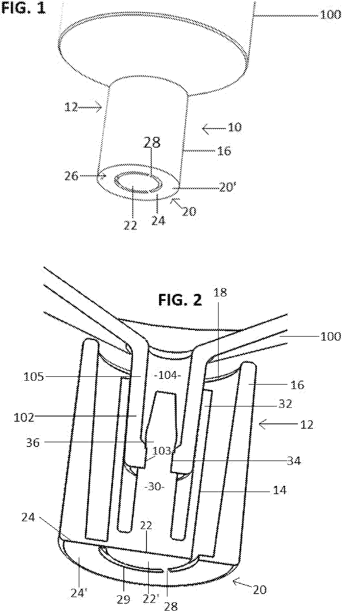
As represented in the accompanying drawings, the present invention is directed to a closure assembly, generally indicated as 10 , and with initial reference to , in one preferred embodiment is represented as being attached to a medical dispenser 100 . As explained herein, the medical dispenser 100 may comprise, but is not limited to, an oral prefilled syringe.
In more specific terms, the closure assembly 10 comprises a one-piece tip cap generally indicated as 12 including a flow restrictor 14 and an outer surrounding sleeve 16 , removably attached to the flow restrictor 14 . The tip cap 12 includes an access opening 18 at least partially defined by the open end of the sleeve 16 . In addition, the closure assembly tip cap 12 includes a closed end generally indicated as 20 comprising an inner end segment 22 , integrally or otherwise connected to the flow restrictor 14 and an outer end segment 24 , integrally or otherwise fixedly connected to the sleeve 16 .
The removable connection between the flow restrictor 14 and the sleeve 16 is accomplished preferably, but not necessarily, by a frangible connection generally indicated as 26 . The frangible connection 26 comprises at least one, but preferably a plurality of frangible tabs 28 removably interconnecting the inner and outer end segments 22 and 24 . Further, the plurality of frangible tabs 28 are disposed in spaced relation to one another about the outer and inner peripheries, respectively of the inner end segment 22 and the outer end segment 24 .
As represented in , the tip cap 12 includes a substantially elongated sealing stem 30 disposed on the interior thereof in surrounded relation to skirt 32 . The sealing stem 30 is cooperatively dimensioned and configured to establish a sealing engagement 34 with the discharge port 102 . Such cooperative dimensioning, between the sealing stem 30 and the discharge port 102 , facilitates sliding entry of the sealing stem 30 through the terminal opening 103 and into the interior of a flow channel 104 of the nozzle 105 of the discharge port 102 . Further, the sealing stem 30 may include a bulbous or enlarged diameter portion 36 , which forces an enlargement of the terminal opening 103 as the bulbous portion 36 passes there through, into the interior of the flow channel 104 . Also, the bulbous portion 36 facilitates the establishment of a frictional, sealing connection 34 , when an installing “push-force” is exerted on the flow restrictor 14 . Also, the presence and dimension of bulbous portion 36 is such as to establish a sufficient resistance to separation of the discharge port 102 from the sealing stem 30 . As a result, the exertion of a “pulling-force” on the medical dispenser 100 , once attached to the sealing stem 30 , is enough to break the frangible connection 26 and force a removal of the flow restrictor 14 from the interior of the sleeve 16 .
The aforementioned installing “push-force” is exerted on the flow restrictor 14 by a forced movement of the medical dispenser 100 , as the discharge port 102 passes through the access opening 18 , into the interior of the closure assembly tip cap 12 . The application of the aforementioned installing “push-force” will be described in greater detail hereinafter, as it applies to both the embodiments of the closure assembly 10 as respectively represented in .
Additional features of the closed end 20 of the tip cap 12 include the exterior surface 20 ′ having a substantially flat configuration, as represented. The flat configuration of the exterior surface of the closed end 20 is defined by the exterior surfaces 22 ′ and 24 ′ of the inner and outer end segments 22 and 24 also being flat and aligned in planar relation. Accordingly, the configuration of the flat exterior surface 20 ′ may comprise and be defined by an aligned planar relation and/or substantially coplanar relation of the exterior surfaces 22 ′ and 24 ′ of the inner and outer end segments 22 and 24 . It is emphasized, the term “coplanar” as used herein, in regard to the alignment of the exterior surfaces 22 ′ and 24 ′ is not necessarily meant to describe a precise coplanar alignment. Rather, the term “coplanar” as used herein is meant to describe a sufficient planar alignment between the exterior surfaces 22 ′ and 24 ′, to accomplish a concurrent disposition of both the exterior surfaces 22 ′ and 24 ′ in supported engagement on a flat supporting surface, such as 300 , schematically represented in , and explained in greater detail hereinafter.
As set forth above, the flow restrictor 14 and the sleeve 16 are removably connected by virtue of the frangible connection 26 and the plurality of frangible tabs 28 serving to interconnect the inner end segment 22 and the outer end segment 24 . When a plurality of the frangible tabs 28 are utilized, they are disposed in spaced relation to one another, as indicated, possibly resulting in a plurality of elongated apertures 29 disposed therebetween. However, the apertures 29 are sufficiently small to restrict or prevent the entrance of any tool, instrument, etc. to pass there-through in an attempt to access the contents of the medical dispenser 100 by defeating the sealing engagement 34 between the flow restrictor 14 and the discharge port 102 .
With reference now to , additional protective features of the tip cap 12 may include the provision of a cover 40 being disposed in covering, overlying relation to the flat exterior surface 20 ’of the closed end 20 . In such a protective position, the cover 40 is also disposed in overlying, covering relation to the substantially coplanar exterior surfaces 22 ′ and 24 ′ of the inner and outer end segments 22 and 24 . As clearly represented in , the cover 40 is fixedly secured, as at 42 , to the outer end segment 24 of sleeve 16 , such as by welding. Further, the cover 40 includes an interior surface 40 ′ which is disposed in spaced, non-engaging relation to the exterior surface 22 ′ of the inner end 22 of the flow restrictor 14 . As such, a minimally dimensioned space 44 exists between the exterior surface 22 ′ of the inner end segment 22 of the flow restrictor 14 and the interior surface 40 ′ of the cover 40 . This spacing 44 prevents an inadvertent attachment or connection between the cover 40 and the inner end segment 22 , when the cover 40 is welded or otherwise fixed, as at 42 , to the exterior surface 24 ′ of the outer end segment 24 of the sleeve 16 .
As a result, the spacing 44 assures that the cover 40 is not inadvertently welded or attached directly to the flow restrictor 14 , via the inner end segment 22 , when the cover 40 is being welded to the exterior surface 24 ′. Also, the spacing 44 is minimally dimensioned to establish the distance between the inner surface 40 ′ and the exterior surface 22 ′ of the inner end segment 22 to be a preferred range of generally about 0.005 inches. This minimal distance (of generally about 0.005 inches) facilitates the establishment of the fluid sealing engagement between the discharge port 102 and the flow restrictor 22 , utilizing the aforementioned inwardly or downwardly directed push-force.
As schematically represented in at least , the exterior surface 40 ″ of the cover 40 , also includes a substantially flat or planar configuration. Accordingly, when the cover 40 is connected to the remainder of the tip cap 12 and the exterior surface 40 ″ is placed on a flat supporting surface 300 , a downwardly directed, installing push-force may be exerted directly on the flow restrictor 14 , as the nozzle 105 of the flow restrictor 102 passes into and through the access opening 18 . Due to the minimal dimension (about 0.005 inches) of the spacing 44 , the downwardly directed push-force 200 will result in a minimal displacement of the flow restrictor 14 , such that the exterior surface 22 ′ will be temporarily deformed or displaced into supported engagement with the interior surface 40 ′ of the cover 40 . Therefore, the minimal dimensioning of the space 44 and the temporary supported engagement of the exterior surface 22 ′ with the interior surface 40 will not significantly displace the plurality of frangible tabs 28 or exert a sufficient force thereon to cause their breakage. As a result, the flow restrictor 14 and the sleeve 16 will remain interconnected by the frangible connection 26 , during the application of the installing “push-force” on the flow restrictor 14 .
With regard to the embodiment of , a similar distribution of the installing push-force 200 will occur, absent the existence of the cover 40 . Moreover, when the flat exterior surface 20 ′ of the closed end 20 is disposed on a flat supporting surface, as at 300 , both of the exterior surfaces 22 ′ and 24 ′ will be concurrently disposed in supported engagement with the supporting surface 300 , due to their substantially coplanar alignment. Similar to the embodiment of , the application of the installing push-force 200 by the insertion of the discharge port 102 into the interior of the tip cap 12 , will result in the push force 200 being primarily, if not exclusively, exerted on the flow restrictor 14 . Concurrently, the exterior surface 22 ′ of the inner end segment 22 thereof will be supported by the supporting surface 300 . Therefore, the plurality of frangible tabs 28 will not be displaced or broken during the application of the push-force 200 . In turn, the frangible connection 26 will remain intact and maintain the connection between the inner and outer end segments 22 and 24 of the flow restrictor 14 and the sleeve 16 .
As represented in , yet another preferred embodiment of the present invention comprises the closure assembly 10 ′ having similar structural and operative features to the embodiments of . However, the closure assembly 10 ′ differs somewhat structurally and operatively by being rotationally connected to the medical dispenser 100 ′ rather than being connected thereto by the aforementioned push-force 200 .
In more specific terms, the closure assembly 10 ′ comprises a tip cap 12 ′ including a flow restrictor 14 ′ disposed within the interior of a sleeve 16 . The flow restrictor 14 ′ and the sleeve 16 are removably connected to one another by means of the frangible connection 26 serving to removably interconnect the inner end segment 22 and the outer end segment 24 , in the manner described above. Also, a skirt 32 is disposed in substantially surrounding relation to the flow restrictor 14 ′ and may serve to align the discharge port 102 ′ with the flow restrictor 14 ′. The flow restrictor 14 ′ differs in structure and function by being rotationally attached to the flow restrictor 102 ′ of the medical dispenser 100 ′. This is accomplished through the provision of an external thread or rib structure 15 being secured to an outermost free end of the flow restrictor 14 ′, disposed opposite to the inner end segment 22 thereof. As also represented, the thread or rib 15 is disposed, dimensioned and configured to rotationally engage the internal threaded surface 106 of the discharge port 102 ′, which surrounds the nozzle 105 thereof and when so connected established a fluid sealing engagement between the flow restrictor 14 ′ and the discharge port 102 ′.
As with the embodiments of , an outward pulling force exerted on the medical dispenser 100 ′, once it is connected to the flow restrictor 14 ′, will result in a breakage of the frangible connection 26 and removal of the connected flow restrictor 14 ′ and the discharge port 102 ′ from the interior of the sleeve 16 . However, as indicated the attachment of the flow restrictor 14 ′ in fluid engaging relation to the discharge port 102 ′ is accomplished by a rotational force being exerted on the closure assembly 10 ′ and/or on the medical dispenser 100 ′.
Therefore, the embodiment of further includes the provision of an attachment member 50 . The attachment member 50 is not initially connected to or structured as an integral or fixed component of the closure assembly 10 ′. Rather, the attachment member 50 is removably connected in at least partially surrounding, rotationally driving engagement with the exterior surface 22 ′ and/or inner end segment 22 of the closed-end 20 . The rotational, driving engagement therebetween is established, at least in part, by a ramp and cliff structure 60 including one or more first ramp and cliff sections 62 formed on and at least partially within the inner end segment 22 of the flow restrictor 14 ′. Further, the ramp and cliff structure 60 also includes at least one second ramp and cliff section 64 formed on the interior surface 52 of the attachment member 50 . Upon engagement of the ramp and cliff sections 62 and 64 and due to the cooperative structuring thereof, a rotational driving force may be exerted on the tip cap 14 ′ by a forced rotation of the attachment members 50 in a single installing (clockwise) direction.
It is to be noted that because the first ramp and cliff section 62 is formed on the inner end segment 22 of the flow restrictor 14 ′ a rotational force applied by the attachment member 50 will only be exerted on the flow restrictor 14 ′ and not the sleeve 16 . As a result, no breakage or disconnecting force will be exerted on the frangible connection 26 , resulting in the flow restrictor 14 ′ and the sleeve 16 remaining in connected engagement with one another, while the rotational installing force is applied to the tip cap 12 ′.
Further, due to the cooperative structuring of the first and second ramp and cliff sections 62 and 64 , rotation of the tip cap 12 ′ in the opposite, rotational direction (counter-clockwise) will be prevented. As a result, the tip cap 12 ′ cannot be unthreaded or rotationally disconnected from the discharge port 102 ′ of the medical dispenser 100 ′, utilizing the attachment member 50 . Therefore, once the tip cap 12 ′ is connected to the medical dispenser 100 ′ by sealing engagement of the flow restrictor 14 ′ with the flow restrictor 102 ′, the tip cap 12 ′ cannot be unthreaded or rotationally disconnected. Access to the contents of the medical dispenser 100 ′ can only be obtained by exerting a pulling or rotational force on the exterior of the sleeve 16 , while it remains attached to the flow restrictor 14 ′. Such pulling or rotational force will result in a breakage of the frangible connection 26 and a removal of the sleeve 16 from the flow restrictor 14 ′ and thereby provide clear evidence of attempted tampering or authorized access.
Since many modifications, variations and changes in detail can be made to the described preferred embodiment of the invention, it is intended that all matters in the foregoing description and shown in the accompanying drawings be interpreted as illustrative and not in a limiting sense. Thus, the scope of the invention should be determined by the appended claims and their legal equivalents.
Figures (4)
Citations
This patent cites (454)
- US722943
- US732662
- US1678991
- US1970631
- US2477598
- US2739590
- US2823674
- US2834346
- US2875761
- US2888015
- US2952255
- US3122280
- US3245567
- US3323798
- US3364890
- US3368673
- US3489268
- US3574306
- US3598120
- US3610241
- US3674181
- US3700215
- US3706307
- US3712749
- US3726445
- US3747751
- US3850329
- US3872867
- US3904033
- US3905375
- US3937211
- US3987930
- US4005739
- US4043334
- US4046145
- US4068696
- US4106621
- US4216585
- US4216872
- US4244366
- US4252122
- US4271972
- US4286591
- US4286640
- US4313539
- US4369781
- US4420085
- US4430077
- US4457445
- US4482071
- USD277783
- US4521237
- US4530697
- US4571242
- US4589171
- US4664259
- US4667837
- US4676530
- US4693707
- US4726483
- US4735617
- US4742910
- US4743229
- US4743231
- US4760847
- US4813564
- US4832695
- US4834706
- US4842592
- US4844906
- US4906231
- US4919285
- US4936445
- US5009323
- US5024323
- US5049129
- US5057093
- US5078696
- USD323392
- US5085332
- US5090564
- US5133454
- US5135496
- US5163922
- US5165560
- US5230429
- US5267983
- US5292308
- US5293993
- US5295599
- US5312367
- US5312368
- US5328466
- US5328474
- US5356380
- US5370226
- US5380295
- US5402887
- US5405339
- US5456668
- US5458580
- US5468224
- US5474178
- US5505705
- US5531695
- US5540666
- US5549571
- US5558648
- US5584817
- US5588239
- US5624402
- US5662233
- US5674209
- US5695470
- US5700247
- US5702374
- US5713485
- US5776124
- US5785691
- US5797885
- US5807343
- US5842567
- USD402766
- US5876381
- US5883806
- US5884457
- US5902269
- US5926922
- US5951522
- US5951525
- US5954657
- US5957166
- US5957314
- US5963136
- US5989227
- US5993437
- US6000548
- USD419671
- US6021824
- US6027482
- US6068614
- USD430293
- US6126640
- USD431864
- US6190364
- US6193688
- US6196593
- US6196998
- US6216885
- US6235376
- US6279746
- US6280418
- US6287671
- US6322543
- US6338200
- US6358241
- US6375640
- US6394983
- US6439276
- US6485460
- US6488666
- US6491665
- US6500155
- US6520935
- US6540697
- US6565529
- US6581792
- US6585691
- US6592251
- US6666852
- US6682798
- US6726652
- US6726672
- US6755220
- US6764469
- US6796586
- US6821268
- USD501549
- US6921383
- US6935560
- US6942643
- US7036661
- US7055273
- US7100771
- US7125397
- US7141286
- US7175081
- US7182256
- US7232066
- US7240926
- US7299981
- US7374555
- US7404500
- US7410803
- US7425208
- US7437972
- USD581046
- USD581047
- USD581049
- US7482166
- US7497330
- US7503453
- USD589612
- US7588563
- US7594681
- US7608057
- US7611487
- US7632244
- US7641636
- USD608900
- US7681606
- USD612939
- US7698180
- US7735664
- US7748892
- US7762988
- US7766919
- US7802313
- US7886908
- US7918830
- US7922213
- US8034041
- US8079518
- US8091727
- US8118788
- US8137324
- US8140349
- US8252247
- US8257286
- US8328082
- US8348895
- US8353869
- US8413811
- US8443999
- USD684057
- US8512277
- US8528757
- US8556074
- US8579116
- US8591462
- US8597255
- US8597271
- US8616413
- US8672902
- USD701304
- US8702674
- US8777910
- US8777930
- US8852561
- US8864021
- US8864707
- US8864708
- US8911424
- US8945082
- US9016473
- US9082157
- US9101534
- US9125976
- USD738495
- USD743019
- US9199042
- US9199749
- US9220486
- US9220577
- US9227019
- USD750228
- US9272099
- US9311592
- US9336669
- USD756777
- USD759486
- USD760384
- USD760902
- US9402967
- US9427715
- US9433768
- US9463310
- USD773043
- USD777903
- US9662456
- US9687249
- USD789529
- US9744304
- US9764098
- USD797928
- USD797929
- US9821152
- USD806241
- US9855191
- USD807503
- USD815945
- US9987438
- USD820187
- US10039913
- USD825746
- USD831201
- US10124122
- US10166343
- US10166347
- US10183129
- US10207099
- USD842464
- USD847373
- US10300263
- US10307548
- US10315024
- US10315808
- US10376655
- USD859125
- US10478262
- US10758684
- US10773067
- US10898659
- US10912898
- US10933202
- US10953162
- US11040149
- US11040154
- US11097071
- US11278681
- USD948713
- US11357588
- US11413406
- US11426328
- US11471610
- US11523970
- US11541180
- US20010034506
- US20010056258
- US20020007147
- US20020023409
- US20020046962
- US20020079281
- US20020097396
- US20020099334
- US20020101656
- US20020104770
- US20020133119
- US20030022685
- US20030146617
- US20030183547
- US20030187403
- US20040008123
- US20040064095
- US20040116858
- US20040173563
- US20040186437
- US20040225258
- US20050146081
- US20050148941
- US20050209555
- US20060084925
- US20060089601
- US20060169611
- US20060173415
- US20060189933
- US20070060898
- US20070106234
- US20070142786
- US20070191690
- US20070219503
- US20070257111
- US20080068178
- US20080097310
- US20080106388
- US20080140020
- US20080243088
- US20080303267
- US20080306443
- US20090084804
- US20090099552
- US20090149815
- US20090166311
- US20090326481
- US20100050351
- US20100084403
- US20100126894
- US20100179822
- US20100228226
- US20100252564
- US20100283238
- US20110044850
- US20110046550
- US20110046603
- US20120064515
- US20120096957
- US20120110950
- US20130018356
- US20130056130
- US20130088354
- US20130237949
- US20130269592
- US20140000781
- US20140034536
- US20140069202
- US20140069829
- US20140076840
- US20140135738
- US20140155868
- US20140163465
- US20140257843
- US20140326727
- US20140353196
- US20150013811
- US20150048045
- US20150112296
- US20150136632
- US20150182686
- US20150191633
- US20150246185
- US20150302232
- US20150305982
- US20150310771
- US20160067144
- US20160067422
- US20160090456
- US20160136352
- US20160144119
- US20160158110
- US20160158449
- US20160176550
- US20160194121
- US20160250420
- US20160279032
- US20160328586
- US20160361235
- US20160367439
- US20170007771
- US20170014310
- US20170124289
- US20170173321
- US20170203086
- US20170225843
- US20170239141
- US20170297781
- US20170319438
- US20170354792
- US20180001540
- US20180014998
- US20180064604
- US20180078684
- US20180089593
- US20180098915
- US20180147115
- US20190308006
- US20190388626
- US20220008645
- US202008018507
- US0148116
- US486367
- USH08002544
- US101159987
- US2008000279
- US2017086607
Cited by (0)
- US12545483: Systems and Methods for Filling and Venting Dropper Bottles
- US12478449: Needle Packaging and Disposal Assembly
- US12383463: Tamper Evident Seal for a Vial Cover
- US12195241: Tamper Evident Integrated Closure
- US12172803: Tamper Evident Integrated Closure
- US12070591: Snap Action Tamper Evident Closure Assembly
- US11904149: Oral Tamper Evident Closure with Retained Indicator