Abstract
An electronic device includes a display panel including a display surface on a front; a front panel surrounding the display panel; a circuit board that is disposed on a front side of a lower portion of the display panel and housed in the front panel; and a holder provided between the front of the display panel and a back of the circuit board. The holder includes a plurality of grooves each continuously extending in an up-down direction on a back of the holder facing the front of the display panel. The plurality of grooves are formed so as to be connected to each other. The front panel is formed with a through hole facing lower ends of the grooves.
Claims (7)
1. An electronic device comprising: a display panel including a display surface on a front; a front panel surrounding the display panel; a circuit board that is disposed on a front side of a lower portion of the display panel and housed in the front panel; and a holder provided between the front of the display panel and a back of the circuit board, wherein the holder includes a plurality of grooves each continuously extending in an up-down direction on a back of the holder facing the front of the display panel, the grooves being formed so as to be connected to each other, and the front panel is formed with a through hole facing lower ends of the grooves.
Show 6 dependent claims
2. The electronic device according to claim 1 , wherein each of the plurality of grooves is formed to be inclined.
3. The electronic device according to claim 1 , wherein the holder includes a protrusion that is fitted in the through hole and is formed at a position of the lower ends of the grooves.
4. The electronic device according to claim 3 , wherein the protrusion includes a cut portion to which the lower ends of the grooves lead and which is provided along the through hole.
5. The electronic device according to claim 1 , wherein the circuit board includes a switch element mounted on the front, and the grooves are formed so as to avoid a position on a back side of the switch element.
6. The electronic device according to claim 1 , wherein the display panel is configured as a touch panel including the display surface of a pressure-sensitive type, and the holder is disposed with a gap between the holder and the display surface.
7. The electronic device according to claim 1 , wherein a passage for sending air is provided outside the front panel at a position of an opening of the through hole.
Full Description
Show full text →
CROSS-REFERENCE TO RELATED APPLICATIONS
This application is a Continuation of PCT International Application No. PCT/JP2019/043753 filed on Nov. 7, 2019 which claims the benefit of priority from Japanese Patent Application No. 2019-043105 filed on Mar. 8, 2019, the entire contents of both of which are incorporated herein by reference.
BACKGROUND OF THE INVENTION
1. Field of the Invention
The present disclosure relates to an electronic device.
2. Description of the Related Art
For example, a display device disclosed in Japanese Patent No. 4842653 includes a display panel and a frame member that supports an outer peripheral portion of a display surface of the display panel. One end of a circuit board is connected to a lower side of the display surface of the standing display panel. A waterproof sheet is attached between the display panel and the frame member at the lower side of the display surface. The waterproof sheet extends along a surface facing the display panel of the frame member, and extends between the circuit board and the frame member. Furthermore, the frame member has a through hole in a portion where the waterproof sheet extends.
In Japanese Patent No. 4842653, for example, when the display surface of the display panel is wiped with a cloth moistened with water, even if water enters the inside the frame member through a gap between the display panel and the frame member, the water is accumulated between a waterproof sheet and the frame member to prevent corrosion of the circuit board due to the accumulated water. Furthermore, in Patent Literature 1, the water accumulated between the waterproof sheet and the frame member can be drained to the outside of the frame member through the through hole.
Japanese Patent No. 4842653 is based on the premise that the water that has entered the inside of the frame member is accumulated between the waterproof sheet and the frame member and then drained to the outside of the frame member through the through hole after being accumulated.
In an electronic device, however, it is not preferable to store water from the viewpoint of protecting an electrical system such as a circuit board even when a waterproof sheet is provided. Therefore, it is desired to drain the water without storing it.
SUMMARY OF THE INVENTION
An electronic device according to an aspect of the present disclosure includes a display panel including a display surface on a front; a front panel surrounding the display panel; a circuit board that is disposed on a front side of a lower portion of the display panel and housed in the front panel; and a holder provided between the front of the display panel and a back of the circuit board. The holder includes a plurality of grooves each continuously extending in an up-down direction on a back of the holder facing the front of the display panel. The plurality of grooves are formed so as to be connected to each other. The front panel is formed with a through hole facing lower ends of the grooves.
The above and other objects, features, advantages and technical and industrial significance of this invention will be better understood by reading the following detailed description of presently preferred embodiments of the invention, when considered in connection with the accompanying drawings.
BRIEF DESCRIPTION OF THE DRAWINGS
is a front view illustrating an electronic device according to an embodiment of the present disclosure;
is an enlarged cross-sectional view taken along line A-A in ;
is a back view of a holder; and
is a partially enlarged perspective view of the holder.
DETAILED DESCRIPTION
Hereinafter, an embodiment for carrying out the present disclosure (hereinafter, referred to as an embodiment) will be described in detail with reference to the drawings. Note that the present disclosure is not limited by the following embodiment. Furthermore, components in the following embodiment include those that can be easily assumed by those skilled in the art, those that are substantially the same, and those within a so-called equivalent range. Moreover, the components disclosed in the following embodiment can be appropriately combined.
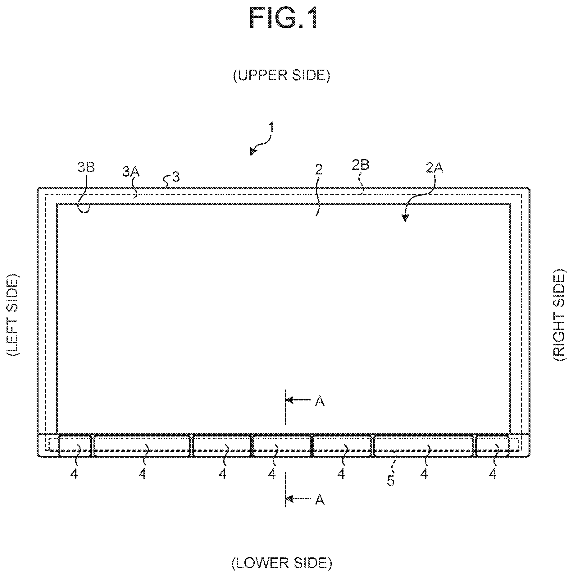
is a front view illustrating an electronic device according to the present embodiment. is an enlarged cross-sectional view taken along line A-A in .
As illustrated in , an electronic device 1 according to the present embodiment is, for example, an audio visual (AV) integrated car navigation device mounted inside a vehicle. The electronic device 1 includes a display panel 2 , a front panel 3 , an operation unit 4 , a circuit board 5 , and a holder 6 .
The display panel 2 is formed in a rectangular shape, and has a display surface 2 A on the front. The front is a surface viewed by an operator. In the case of a car navigation device, the car navigation device is disposed in a front portion of a vehicle, so that the front faces the rear of the vehicle. The display surface 2 A has a rectangular shape smaller than the rectangular shape of the display panel 2 , and is disposed inside an outer edge 2 B of the display panel 2 . In the present embodiment, the display panel 2 is a touch panel having a pressure-sensitive display surface 2 A.
The front panel 3 is formed in a rectangular shape so as to surround the display panel 2 . The front panel 3 includes a rectangular frame portion 3 A and a rectangular window portion 3 B. The frame portion 3 A surrounds the display panel 2 . The window portion 3 B opens the display surface 2 A of the display panel 2 inside the frame portion 3 A.
As illustrated in , a plurality of operation units 4 are arranged side by side in a left-right direction on the front side of the front panel 3 and on the lower side of the front panel 3 . Note that the left and right are the case when viewed from the front side as illustrated in . The “right side” and the “left side” in , which is described below, viewed from the back side are also indicated based on the case when viewed from the front side. As illustrated in , the operation unit 4 includes a key 4 A, a knob 4 B, and a hinge 4 C. The key 4 A is a portion provided on the outer front side of the front panel 3 . An operator pushes and operates the key 4 A. The knob 4 B is disposed on the back side of the key 4 A, and the hinge 4 C is integrally connected to the back side of the knob 4 B. The knob 4 B and the hinge 4 C are formed of resin material and the like. The hinge 4 C is formed in a rod or plate shape so as to be elastically deformed, and is formed in a curved or bent manner. Therefore, the knob 4 B is movable to the back side together with the key 4 A due to deformation of the hinge 4 C when the key 4 A is pushed to the back side by the operator. Furthermore, when the key 4 A is not operated by the operator, the elasticity of the hinge 4 C biases the knob 4 B together with the key 4 A to the front side. Note that, as illustrated in , the front panel 3 is provided with a guide portion 3 C so as to surround the upper, lower, right, and left sides of the knob 4 B. The front panel 3 guides the movement of the knob 4 B with the guide portion 3 C. The key 4 A is disposed to cover the front side of the guide portion 3 C so as not to prevent the movement of the knob 4 B.
The circuit board 5 is disposed along the front of the display panel 2 in the lower portion of the display panel 2 . In the present embodiment, the circuit board 5 is continuously provided in the left-right. As illustrated in , a tact switch, which is a switch element 5 A, is mounted on the front of the circuit board 5 . The switch element 5 A is disposed so as to face the back side of the knob 4 B of each of a plurality of operation units 4 . Therefore, when the key 4 A is pushed by the operator to the back side, the switch element 5 A operates by movement of the knob 4 B to the back side together with the key 4 A due to deformation of the hinge 4 C. Note that, as referred to in , not one but a plurality of (two in present embodiment) switch elements 5 A may be provided on the back side of one operation unit 4 . The circuit board 5 is housed in the front panel 3 . Specifically, a case 3 D is formed in the front panel 3 . The case 3 D extends to the back more than the above-described guide portion 3 C, and surrounds the upper, lower, right, and left sides. The circuit board 5 is housed in the case 3 D.
As illustrated in , the holder 6 is provided in the lower portion of the display panel 2 so as to be sandwiched between the front of the display panel 2 and the back of the circuit board 5 . The holder 6 is formed in a plate shape, is provided so as to close the back side of the case 3 D of the front panel 3 in which the circuit board 5 is housed, and is attached to the front panel 3 . Specifically, the holder 6 includes protrusions 6 A to be inserted into through holes 3 E formed in the bottom portion of the front panel 3 . The holder 6 is attached to the front panel 3 by fitting the protrusions 6 A into the through holes 3 E.
Furthermore, the holder 6 is provided in contact with the back of the circuit board 5 by being attached to the front panel 3 . As described above, when the key 4 A is pushed to the back side by the operator, the switch element 5 A of the circuit board 5 operates by movement of the knob 4 B together with the key 4 A to the back side due to deformation of the hinge 4 C. At the time, the holder 6 abuts on the back of the circuit board 5 to generate reaction force against the circuit board 5 being pushed toward the back side.
Furthermore, the holder 6 is provided in contact with the front of the display panel 2 by being attached to the front panel 3 . However, since the display panel 2 is configured as a touch panel including a pressure-sensitive display surface 2 A in the present embodiment, it is necessary to prevent the holder 6 from coming into contact with the display surface 2 A. For that reason, the holder 6 is formed with a stepped portion 6 B that protrudes to the back side on the lower side of a region (broken line L in ) of the display surface 2 A, and a gap S 1 is provided between the holder 6 and the front of the display surface 2 A. Similarly, a gap S 2 is provided between the front panel 3 and the front of the display surface 2 A in order to prevent the front panel 3 from coming into contact with the display surface 2 A.
As described above, the gaps S 1 is provided between the holder 6 and the front of the display surface 2 A, and the gap S 2 is provided between the front panel 3 and the front of the display surface 2 A. Therefore, for example, when the display surface 2 A is wiped with a cloth containing water or a beverage is accidentally splashed on the display surface 2 A, water (water or beverage is collectively referred to as water) may enter the inside of the front panel 3 from the gaps S 1 and S 2 , and may affect the circuit board 5 and the electrical system of the display panel 2 . The electronic device 1 of the present embodiment is provided with a drainage structure against such entering of water.
Hereinafter, the drainage structure will be described. is a back view of the holder. is a partially enlarged perspective view of the holder.
As illustrated in to 4 , the plurality of grooves 6 C each continuously extending in an up-down direction on the back, which faces the display panel 2 , of the above-described holder 6 . Upper ends 6 Ca of the grooves 6 C open at the stepped portion 6 B. Each of the grooves 6 C continuously formed downward at a portion where the holder 6 is in contact with the front of the display panel 2 on the lower side of the stepped portion 6 B. Lower ends 6 Cb of the grooves 6 C (at least two grooves) are formed so as to be connected to each other. The connection of the grooves 6 C may not necessarily obtained by the connection of the lower ends 6 Cb. Instead, in the case of two grooves 6 C, the lower end 6 Cb of one groove 6 C may be connected to the middle of the other groove 6 C, for example. As illustrated in , each of the grooves 6 C has different right and left positions of the upper end 6 Ca and the lower end 6 Cb with respect to the vertical direction. Each of the grooves 6 C is formed so as to be inclined in the left-right direction from the upper end 6 Ca to the lower end 6 Cb between the upper end 6 Ca and the lower end 6 Cb when viewed from the back (front). The inclination is preferably linearly formed, but may be curved or bent. Furthermore, as illustrated in , the grooves 6 C are formed so as to avoid a position on the back side of the switch element 5 A mounted on the front of the circuit board 5 .
Furthermore, a flange portion 6 D protruding toward the back side is formed at the lower end of the holder 6 , and the protrusion 6 A is formed on the lower side of the flange portion 6 D. The lower end 6 Cb of each of the grooves 6 C extends to the position of the flange portion 6 D. The flange portion 6 D and the protrusion 6 A are formed with a cut portion 6 E to which the lower ends 6 Cb of the grooves 6 C extending to the position of the flange portion 6 D lead. The cut portion 6 E continuously extends downward from the lower ends 6 Cb of the grooves 6 C to the lower end of the protrusion 6 A. The cut portion 6 E is formed so as to open to the upper side of the flange portion 6 D, the back side of the protrusion 6 A, and the lower side of the protrusion 6 A. As illustrated in , when the protrusion 6 A is inserted into the through hole 3 E of the front panel 3 , the cut portion 6 E extends in the up-down direction along the through hole 3 E, and leads from the bottom of the front panel 3 to the outside of the front panel 3 . Therefore, the lower ends 6 Cb of the grooves 6 C lead from the bottom of the front panel 3 to the outside of the front panel 3 through the cut portion 6 E and the through hole 3 E.
As described above, the electronic device 1 of the present embodiment includes: the display panel 2 including the display surface 2 A on the front; the front panel 3 surrounding the display panel 2 ; the circuit board 5 that is disposed on the front side of the lower portion of the display panel 2 and housed in the front panel 3 ; and the holder 6 provided between the front of the display panel 2 and the back of the circuit board 5 . The holder 6 includes the plurality of grooves 6 C each continuously extending in the up-down direction on the back of the holder 6 facing the front of the display panel 2 . The grooves 6 C are formed so as to be connected to each other. The front panel 3 is formed with the through hole 3 E facing the lower ends 6 Cb of the grooves 6 C.
Therefore, when water flowing on the front surface of the display panel 2 enters the inside of the front panel 3 through the above-described gaps S 1 and S 2 , the water can be drained from the grooves 6 C to the outside of the front panel 3 through the through hole 3 E, by using the grooves 6 C formed on the back facing the front of the display panel 2 in the holder 6 and the through hole 3 E formed so as to face the lower ends 6 Cb of the grooves 6 C in the front panel 3 . In addition, since the plurality of grooves 6 C are connected to each other, good drainage efficiency can be achieved without providing a plurality of through holes 3 E corresponding to the plurality of grooves 6 C, respectively. As a result, the electronic device 1 of the present embodiment can improve the drainage performance.
Furthermore, the groove 6 C is formed to be inclined.
Therefore, the inclined groove 6 C guides water from some portions of the plurality of grooves 6 C to the through hole 3 E. As a result, the electronic device 1 of the present embodiment can improve the performance of draining water that has enters the inside.
Furthermore, the holder 6 includes the protrusion 6 A fitted in the through hole 3 E and formed at the position of the lower ends 6 Cb of the grooves 6 C.
The holder 6 is attached to the front panel 3 by fitting the protrusion 6 A into the through hole 3 E. Therefore, the through hole 3 E for attaching the holder 6 can also be used for drainage, and water can be drained by using a portion where the holder 6 and the front panel 3 are in contact with each other.
Furthermore, the protrusion 6 A has the cut portion 6 E. The lower ends 6 Cb of the grooves 6 C lead to the cut portion 6 E. The cut portion 6 E is provided along the through hole 3 E.
Therefore, water passing through the grooves 6 C can be drained from the cut portion 6 E of the protrusion 6 A through the through hole 3 E, and the drainage performance can be further improved.
Furthermore, the circuit board 5 includes the switch element 5 A mounted on the front. As illustrated in , the grooves 6 C are formed so as to avoid the position on the back side of the switch element 5 A.
When the switch element 5 A is pushed and operated from the front, the circuit board 5 is pushed to the back side, and the holder 6 generates reaction force to support the circuit board 5 . When the grooves 6 C are positioned on the back side of the switch element 5 A, the holder 6 has difficulty in generating the reaction force, which may cause deterioration of a function of supporting the circuit board 5 . For that reason, the grooves 6 C that are formed so as to avoid the position on the back side of the switch element 5 A allows the holder 6 to generate the reaction force and have a secure function of supporting the circuit board 5 while improving the drainage performance. The fact that the groove 6 C is formed so as to avoid the position on the back side of the switch element 5 A means that even if the groove 6 C overlaps a part of the back side of the switch element 5 A, the other part is avoided. Furthermore, in a form in which the grooves 6 C avoid the position on the back side of the switch element 5 A, the grooves 6 C are preferably formed in a line shape narrower than the area on the back side of the switch element 5 A.
Furthermore, the display panel 2 is configured as a touch panel including a pressure-sensitive display surface 2 A, and the holder 6 is disposed with the gap S 1 between the holder 6 and the display surface 2 A.
In the display panel 2 configured as a touch panel including a pressure-sensitive display surface 2 A, erroneous operation may occur when the holder 6 comes in contact with the display panel 2 , so that the gap S 1 is needed. For that reason, water is likely to enter through the gap S 1 . However, since the electronic device 1 of the present embodiment has the improved drainage performance, the drainage can be ensured with the gap S 1 while ensuring the function of the pressure-sensitive touch panel.
Furthermore, in the electronic device 1 of the present embodiment, as illustrated in , a passage R for sending air is provided outside the front panel 3 at a position of the opening of the through hole 3 E.
The passage R is provided so as to generate a flow of air passing through the position of the opening of the through hole 3 E. In the electronic device 1 mounted inside a vehicle, the passage R can be achieved by generating wind with an air conditioner. Then, the air flow generates a negative pressure at the opening of the through hole 3 E, and water is drained from the through hole 3 E to the outside of the front panel 3 . As a result, the electronic device 1 of the present embodiment can improve the drainage performance.
According to the present disclosure, when water flowing on the front surface of a display panel enters the inside of the front panel, the water can be drained from the grooves to the outside of the front panel through the through hole, by using the grooves formed on the back facing the front of the display panel in the holder and the through hole formed so as to face the lower end of the groove in the front panel. In addition, since the plurality of grooves are connected to each other, high drainage efficiency can be achieved without providing a plurality of through holes corresponding to the plurality of grooves, respectively. As a result, according to the present disclosure, drainage performance can be improved.
Figures (4)
Citations
This patent cites (14)
- US7911555
- US8208272
- US9116376
- US9491893
- US10070540
- US20040135482
- US20050105012
- US20070188675
- US20100246157
- US20120194971
- US20130170156
- US20140009717
- US4842653
- US2013-003195