TOF Camera Device and Method of Driving the Same
Abstract
A time of flight (TOF) camera device and a method of operating the same is provided. The time of flight (TOF) camera device includes a pulse generator configured to generate a pulse signal, a light module configured to emit output light to at least one object in response to the pulse signal, a three-dimensional (3D) sensor configured to receive reflected light when the output light is reflected by the at least one object for a first frame, a distance calculator configured to receive an output of the 3D sensor and generate a distance data signal, and a light density control device configured to receive the distance data signal from the distance calculator and output a light density control signal. The light density control signal may adjust the size of an opening in the light module to change a projected area from the output light onto the at least one object.
Claims (20)
1. A time of flight (TOF) camera device comprising: a pulse generator configured to generate a pulse signal; a light module configured to emit an output light onto at least one object in response to the pulse signal; a three-dimensional (3D) sensor configured to receive reflected light when the output light is reflected by the at least one object for a first frame; a distance calculator configured to receive an output of the 3D sensor and generate a distance data signal; and a light density control device configured to receive the distance data signal from the distance calculator and output a light density control signal, wherein the light density control signal controls a size of an opening within the light module through which the output light is emitted to determine a size of a projected area onto the at least one object, wherein the light module emits the output light to a first area of the at least one object for the first frame, and wherein the light density control signal changes the size of the opening of the light module in response to the distance data signal to emit the output light to a second area of the at least one object in a second frame, wherein the second area is different from the first area.
9. A method of driving a time of flight (TOF) camera device, comprising: generating a pulse signal; emitting output light in a first frame through an opening to a first area of at least one object in response to the pulse signal, wherein a size of the opening determines a projected area of light on the at least one object; receiving reflected light when the output light is reflected by the at least one object for the first frame; generating a distance data signal from the received reflected light; generating a light density control signal based on the distance data signal; changing the size of the opening through which the output light is emitted in a second frame based on the light density control signal; and emitting the output light through the opening to a second area of the at least one object, wherein the second area is different from the first area.
17. A method of driving a time of flight (TOF) camera device, comprising: emitting, by a light module, first output light to a first area of a first object for a first frame; changing an area, to which the first output light is emitted to the first object, from the first area to a second area based on first reflected light reflected by the first object for the first frame; emitting, by the light module, second output light to a third area of a second object for a second frame subsequent to the first frame; and changing an area, to which the second output light is emitted to the second object, from a third area to a fourth area based on second reflected light reflected by the second object for the second frame, wherein a size of the second area is different from a size of the fourth area.
Show 17 dependent claims
2. The TOF camera device of claim 1 , wherein the 3D sensor is configured to: generate time information of the received reflected light based on phase difference information, wherein the phase difference information comprises a difference between a phase of the output light of the light module and a phase of the reflected light reflected by the object; and generate a 3D depth map of the object based on the time information.
3. The TOF camera device of claim 2 , wherein: the at least one object includes a first object separated from the light module by a first distance and a second object separated from the light module by a second distance greater than the first distance; and the 3D depth map is generated by combining a depth of the first object and a depth of the second object.
4. The TOF camera device of claim 2 , wherein the 3D sensor generates the 3D depth map by successively combining rays of reflected light reflected by the at least one object.
5. The TOF camera device of claim 2 , wherein the 3D sensor generates the 3D depth map by combining rays of the reflected light reflected by the at least one object.
6. The TOF camera device of claim 1 , wherein: the light module includes a light density controller; and the light density controller adjusts the size of the opening, through which the output light is emitted, in response to the light density control signal.
7. The TOF camera device of claim 6 , wherein the light density controller adjusts the size of the opening from a first size to a second size smaller than the first size in response to the light density control signal.
8. The TOF camera device of claim 6 , wherein: the at least one object includes a first object separated from the light module by a first distance and a second object separated from the light module by a second distance greater than the first distance; and the light density control device selects the first object or the second object and outputs the light density control signal based on the selected object.
10. The method of claim 9 , further comprising: generating time information of the received reflected light based on phase difference information between the output light and the reflected light reflected by the at least one object; and generating a three-dimensional (3D) depth map of the at least one object based on the time information, wherein the distance data signal is generated based on the 3D depth map.
11. The method of claim 10 , wherein: the at least one object includes a first object separated from a light module by a first distance and a second object separated from the light module by a second distance greater than the first distance; and the 3D depth map is generated by combining a depth of the first object and a depth of the second object.
12. The method of claim 10 , wherein the generating of the 3D depth map of the at least one object includes successively combining rays of the reflected light reflected by the at least one object to generate the 3D depth map.
13. The method of claim 10 , wherein the generating of the 3D depth map of the at least one object includes combining rays of the reflected light reflected by the at least one object to generate the 3D depth map.
14. The method of claim 9 , wherein the light density control signal based on the distance data signal controls the size of the opening through which the output light is emitted.
15. The method of claim 14 , wherein the light density control signal allows the size of the opening to be adjusted from a first size to a second size smaller than the first size.
16. The method of claim 14 , wherein: the at least one object includes a first object separated from a light module by a first distance and a second object separated from the light module by a second distance greater than the first distance; and the outputting of the light density control signal includes selecting the first object or the second object and outputting the light density control signal based on the selected object.
18. The method of claim 17 , wherein: the first object is disposed at a position separated from the light module by a first distance; and the second object is disposed at a position separated from the light module by a distance different from the first distance.
19. The method of claim 17 , wherein: a size of the first area is greater than the size of the second area; and a size of the third area is greater than the size of the fourth area.
20. The method of claim 17 , wherein: the first object is disposed at a position separated from the light module by a first distance; the second object is disposed at a position farther from the light module than the first distance; and the size of the fourth area is smaller than the size of the second area.
Full Description
Show full text →
CROSS-REFERENCE TO RELATED APPLICATION
This application claims priority under 35 USC § 119 to Korean Patent Application No. 10-2020-0172917 filed on Dec. 11, 2020 in the Korean Intellectual Property Office, the disclosure of which is incorporated herein by reference in its entirety.
TECHNICAL FIELD
The present disclosure relates to a time of flight (TOF) camera device and a method of driving the same.
DISCUSSION OF THE RELATED ART
A time of flight (TOF) camera may detect the distance of an object from the camera by measuring a phase delay in the light emitted from the camera and bounced off the object. For example, some conventional TOF cameras may modulate a light source with a predetermined frequency, emit the modulated light onto a scene, and measure the phase shift of the light reflected back into the camera in order to generate a depth map at a resolution determined by the camera's design. These types of cameras are widely used in the topographic surveying and object attitude control fields.
SUMMARY
Embodiments of the present disclosure provide a time of flight (TOF) camera device configured to accurately identify a position of an object by controlling light density.
Embodiments of the present disclosure also provide a method of driving the TOF camera device configured to accurately identify a position of an object by controlling light density.
Aspects of the present disclosure are not necessarily limited to those set forth herein, and other aspects of the present disclosure will be apparent to those skilled in the art from the following description.
According to an aspect of the present disclosure, a time of flight (TOF) camera device includes: a pulse generator configured to generate a pulse signal, a light module configured to emit output light to at least one object in response to the pulse signal, a three-dimensional (3D) sensor configured to receive reflected light when the output light is reflected by the at least one object for a first frame, a distance calculator configured to receive an output of the 3D sensor and generate a distance data signal, and a light density control device configured to receive the distance data signal from the distance calculator and output a light density control signal, where the light density control signal controls the size of an opening within the light module through which the output light is emitted to determine a size of a projected area on the at least one object, and where the light module emits the output light to the at least one object for the first frame, wherein the output light has a light density corresponding to the light density control signal.
According to an aspect of the present disclosure, a method of driving a time of flight (TOF) camera device includes: generating a pulse signal, emitting output light to at least one object in response to the pulse signal, receiving reflected light when the output light is reflected by the at least one object for a first frame, generating a distance data signal from the received reflected light and receiving the distance data signal and outputting a light density control signal allowing a size of an area, to which the output light is emitted to the at least one object, to be determined based on the distance data signal.
According to an aspect of the present disclosure, a method of driving a time of flight (TOF) camera device includes: emitting, by a light module, first output light to a first area of a first object for a first frame, changing an area, to which the first output light is emitted to the first object, from the first area to a second area based on first reflected light reflected by the first object for the first frame, emitting, by the light module, second output light to a third area of a second object for a second frame subsequent to the first frame and changing an area, to which the second output light is emitted to the second object, from a third area to a fourth area based on second reflected light reflected by the second object for the second frame, wherein a size of the second area is different from a size of the fourth area.
BRIEF DESCRIPTION OF THE DRAWINGS
The above and other aspects and features of the present disclosure will become more apparent by describing in detail exemplary embodiments thereof with reference to the attached drawings, in which:
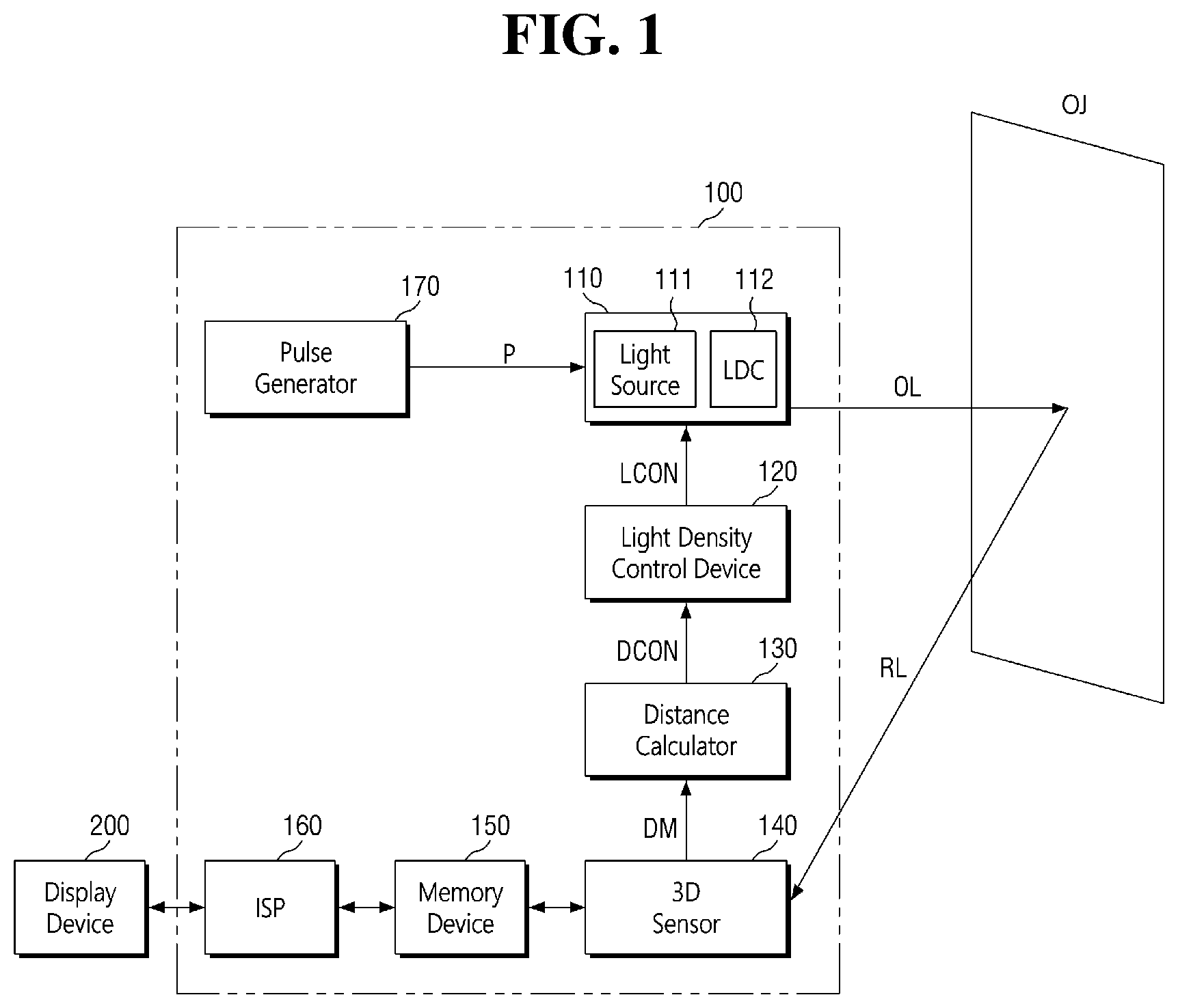
is a block diagram illustrating a time of flight (TOF) camera device.
is a diagram illustrating an optical area of an object according to a size of an opening of a light density controller (LDC) according to some embodiments.
is a diagram illustrating an optical area of an object according to a size of an opening of an LDC according to some embodiments.
is a diagram illustrating an optical area of an object according to a size of an opening of an LDC according to some embodiments.
illustrates an example process of generating a 3D depth map from a 3D sensor according to some embodiments.
illustrates an example process of generating a 3D depth map from a 3D sensor according to some embodiments.
is a flowchart of a method of driving the TOF camera device.
is a diagram illustrating an optical area of a first object and an optical area of a second object according to a size of the opening of the LDC according to some embodiments.
illustrates example depth maps of the first object and the second object according to some embodiments.
is a diagram illustrating a case in which the first object of is selected.
is a diagram illustrating an optical area of the first object and an optical area of the second object according to .
is a diagram illustrating a case in which the second object of is selected.
is a diagram illustrating an optical area of the first object and an optical area of the second object according to .
is a flowchart of a method of driving the TOF camera device according to some embodiments.
is a diagram illustrating optical areas of a first object and a second object according to a size of the opening of the LDC according to some embodiments.
is a diagram illustrating a state in which output light is emitted to the first object for a first frame.
is a diagram illustrating an optical area of the first object according to .
is a diagram illustrating a state in which the output light is emitted to the second object for a second frame.
is a diagram illustrating an optical area of the second object according to .
is a diagram illustrating a computer system including the TOF camera device illustrated in according to some embodiments.
is a diagram illustrating a computer system including the TOF camera device illustrated in according to some embodiments.
is a diagram illustrating a computer system including the TOF camera device illustrated in according to some embodiments.
DETAILED DESCRIPTION OF THE EMBODIMENTS
Hereinafter, embodiments of the present disclosure will be described with reference to the accompanying drawings. Like reference symbols in the drawings may denote like elements, and to the extent that a description of an element has been omitted, it may be understood that the element is at least similar to corresponding elements that are described elsewhere in the specification.
In conventional phase detection TOF cameras, the accuracy of the TOF camera depends on the modulation frequency, dynamic range, sensitivity, and other properties of the emitted light. Further, if the phase shift is large enough from a very far object, then it may not be possible to determine the distance to the object, as the measured range is determined by a modulo operation on the carrier wavelength (e.g., the phase shift may be large enough that it shifts beyond a full wavelength, yielding an uninterpretable result). In conventional phase detection TOF cameras where the modulation frequency is fixed, it may not be possible to secure accurate results beyond a fixed distance.
The TOF camera device and systems described herein may accurately track the distance of multiple objects over time. Specifically, a TOF camera device according to embodiments of the present disclosure may include a light density control device, which may be configured to determine the distance of one or more objects, and adjust a projected angle of light which determines a corresponding optical area onto the one or more objects, thereby tracking the one or more objects across a wide distance range with increased accuracy.
is a block diagram illustrating a time of flight (TOF) camera device. is a diagram illustrating an optical area of an object according to a size of an opening of a light density controller (LDC) according to some embodiments. is a diagram illustrating an optical area of an object according to a size of an opening of an LDC according to some embodiments. is a diagram illustrating an optical area of an object according to a size of an opening of an LDC according to some embodiments.
Referring to , a TOF camera device 100 may include a light module 110 , a light density control device 120 , a distance calculator 130 , a three-dimensional (3D) sensor 140 , a memory device 150 , an image signal processor (ISP) 160 , and a pulse generator 170 .
The light module 110 may include a light source 111 and an LDC 112 . The light source 111 may emit output light OL to an object OJ in response to a pulse signal P generated by the pulse generator 170 .
The LDC 112 may control an opening thereof, through which the output light OL is emitted, in response to a light density control signal LCON generated by the light density control device 120 . For example, the LDC 112 may control the size of the opening, through which the output light OL is emitted, in response to the light density control signal LCON according to a position of the object OJ.
Referring to , the light module 110 may emit the output light OL to the object OJ. In this case, a gap of the LDC 112 may be a first gap d 1 . In addition, the light module 110 may project the output light OL onto the object OJ over an area of the object; this projected area may be referred to as an optical area, and may be a first area S 11 .
Referring to , the light density control signal LCON may be changed. In the example illustrated in , the distance between the light module 110 and the object OJ may be less than the distance of the example illustrated in . Further, the LDC 112 may increase a size of the opening of the LDC 112 in response to the light density control signal LCON. The LDC 112 may control the size of the opening, through which the output light OL is emitted, in response to the light density control signal LCON.
In , a gap of the LDC 112 may be a second gap d 2 , and a size of the second gap d 2 may be greater than the first gap d 1 (see ).
As a result, the optical area of the output light OL emitted onto the object OJ may be increased. For example, a size of the optical area of the output light OL emitted onto the object OJ may be increased from the first area S 11 (see ) to a second area S 12 .
Conversely, referring to , a distance between the light module 110 and the object OJ may be a distance greater than the distance between the light module 110 and the object OJ as illustrated in , and a size of the opening of the LDC 112 may be decreased in response to the light density control signal LCON.
In , a gap of the LDC 112 may be a third gap d 3 . A size of the third gap d 3 may be smaller than the size of the first gap d 1 . The size of the third gap d 3 may be smaller than the size of the second gap d 2 .
As a result, an optical area of the output light OL emitted onto the object OJ may be decreased. For example, a size of the optical area, to which the output light OL is emitted onto the object OJ may be decreased from the first area S 11 (see ) to a third area S 13 .
As described above, the size of the optical area of the output light OL emitted onto the object OJ may be changed according to the size of the opening of the LDC 112 .
Further referring to , the output light OL may have a constant frequency. For example, a light source in an infrared light wavelength range may be used in the light module 110 , but the embodiments are not necessarily limited thereto.
The output light OL emitted to the object OJ may be reflected and received by the 3D sensor 140 . A phase of reflected light RL reflected by the object OJ may be changed with reference to the phase of the output light OL.
For example, when the phase of the reflected light RL is compared with a phase of the output light OL emitted by the light source 111 , the phase of the reflected light RL may be changed according to the distance to the object OJ.
The 3D sensor 140 may receive the reflected light RL, which is the output light OL reflected by the object OJ, for a first frame. The 3D sensor 140 may store phase difference information about the reflected light RL in the memory device 150 .
The 3D sensor 140 may generate time information of the received reflected light RL from the phase difference information between the output light OL of the light module 110 and the reflected light RL reflected by the object OJ. From the time information, the 3D sensor 140 may generate a 3D depth map DM of the object OJ.
A description of the 3D sensor 140 for generating the 3D depth map DM will be described below with reference to .
The distance calculator 130 may receive an output of the 3D sensor 140 to generate a distance data signal DCON. In this case, the output of the 3D sensor 140 may be, for example, the 3D depth map DM.
The distance data signal DCON may be a signal based at least in part on the time information between the output light OL and the reflected light RL.
The light density control device 120 may receive the distance data signal DCON from the distance calculator 130 and output the light density control signal LCON in response. The light density control signal LCON may determine a size of an area to which the output light OL emitted by the light module 110 . For example, the light density control signal LCON may determine the size of a gap in the LDC 112 , thereby projecting the output light OL onto the object OJ in an area, where the area has a size determined by the gap in the LDC 112 .
The light density control device 120 may receive the distance data signal DCON to generate the light density control signal LCON. The light density control signal LCON may allow the size of the opening, through which the output light OL of the LDC 112 is emitted, to be adjusted.
The memory device 150 may store information received from the 3D sensor 140 . The memory device 150 may transmit the 3D depth map DM, an image, and the phase difference information generated by the 3D sensor 140 to the ISP 160 .
The ISP 160 may calculate a distance between the object OJ and the TOF camera device 100 using the phase difference information. The ISP 160 may transmit calculated information or the image to a display device 200 . The display device 200 may then display the image.
illustrates an example process of generating a 3D depth map from a 3D sensor according to some embodiments. illustrates an example process of generating a 3D depth map from a 3D sensor according to some embodiments.
Referring to , the 3D sensor 140 may receive and combine rays of reflected light RL reflected by the object to generate a 3D depth map DM.
For example, the 3D sensor 140 may receive the rays of the reflected light reflected by the object OJ for a first frame. The 3D sensor 140 may combine the rays of the reflected light to generate the 3D depth map DM.
Referring to , unlike , the 3D sensor 140 may generate a 3D depth map DM in which rays of reflected light RL reflected by the object are successively combined.
For example, the 3D sensor 140 may receive multiple rays of the reflected light reflected by the object OJ for a first frame. The 3D sensor 140 may successively combine the multiple rays of the reflected light to generate single rays SRL 1 to SRLm of reflected light so as to generate the 3D depth map DM.
is a flowchart illustrating a method of driving the TOF camera device.
Referring to , a pulse signal is generated (S 100 ).
Referring to , the pulse generator 170 may generate a pulse signal P. Hereinafter, the method of driving the TOF camera device according to embodiments of the present disclosure will be described using the structure of the TOF camera device 100 described above. However, the embodiments are not necessarily limited thereto.
Next, output light is emitted to the object in response to the pulse signal (S 110 ).
Referring to , the light module 110 may emit output light OL to the object OJ in response to the pulse signal P generated by the pulse generator 170 . For example, the light source 111 of the light module 110 may emit the output light OL to the object OJ in response to the pulse signal P.
Next, the reflected light reflected by the object is received by the 3D sensor 140 (S 120 ).
Referring to , the 3D sensor 140 may receive the reflected light RL reflected by the object OJ.
Next, a 3D depth map is generated using the received reflected light (S 130 ).
Referring to , the 3D sensor 140 may generate time information of the received reflected light RL on the basis of phase difference information between the output light OL of the light module 110 and the reflected light RL reflected by the object OJ. The 3D sensor 140 may generate a 3D depth map DM of the object OJ from the time information.
Referring to , in a case in which the 3D sensor 140 generates a 3D depth map DM, multiple rays of reflected light RL reflected by the object OJ may be successively combined to generate single rays SRL 1 to SRLm of the reflected light so as to generate the 3D depth map DM. For example, the 3D depth map DM may be generated using the single rays SRL 1 to SRLm of the reflected light for each of frames F 1 to Fn.
Referring to , in the case in which the 3D sensor 140 generates a 3D depth map DM, the rays of reflected light reflected by the object OJ may be combined to generate the 3D depth map DM.
Next, a distance data signal is generated from the generated 3D depth map (S 140 ).
Referring to , the distance calculator 130 may generate a distance data signal DCON. The distance calculator 130 may receive the 3D depth map DM, output from the 3D sensor 140 , to generate the distance data signal DCON.
Finally, a light density control signal may be output which allows a size of an area to which the output light is emitted onto the object to be determined using the distance data signal (S 150 ).
Referring to , the light density control device 120 may generate a light density control signal LCON. The light density control device 120 may determine the size of the area to which the output light OL emitted by the light module 110 onto the object. The light density control device 120 may receive the distance data signal DCON and output the light density control signal LCON on the basis of the distance data signal DCON.
Accordingly, the LDC 112 may adjust a size of the opening thereof through which the output light OL is emitted in response to the light density control signal DCON. The output light OL corresponding to the light density control signal DCON may be emitted to the object OJ.
In to 7 , the case in which one object OJ is present for the first frame has been described, and hereinafter, an example in which two objects are present for the first frame will be described. Hereinafter, descriptions of the same or similar components as those of to 7 will be omitted or only briefly described, and differences therebetween will be mainly described.
is a diagram illustrating an optical area of a first object and an optical area of a second object according to a size of the opening of the LDC according to some embodiments. illustrates example depth maps of the first object and the second object according to some embodiments. is a diagram illustrating a case in which the first object of is selected. is a diagram illustrating an optical area of the first object and an optical area of the second object according to . is a diagram illustrating a case in which the second object of is selected. is a diagram illustrating an optical area of the first object and an optical area of the second object according to .
Referring to , a first object OJ 1 may be separated from the light module 110 by a first distance D 1 , and a second object OJ 2 may be separated from the light module 110 by a second distance D 2 greater than the first distance D 1 .
For a first frame, the light source 111 may emit output light OL to the first object OJ 1 and the second object OJ 2 in response to a pulse signal P. For example, the output light OL emitted by the light module 110 may be emitted to both of the first object OJ 1 and the second object OJ 2 .
In this case, an area to which the output light OL is emitted onto the first object OJ 1 may be a first area 51 , and an area to which the output light OL is emitted onto the second object OJ 2 may be a second area S 2 .
The 3D sensor 140 may receive first reflected light RL 1 when the output light OL is reflected by the first object OJ 1 , and may receive a second reflected light RL 2 when the output light OL is reflected by the second object OJ 2 for the first frame. The 3D sensor 140 may combine a depth of the first object OJ 1 and a depth of the second object OJ 2 to generate a 3D depth map OJS.
Referring to , since the first object OJ 1 is positioned at a first distance D 1 , which is relatively closer to the light module 110 than the second object OJ 2 , a depth map thereof may be generated with a flood depth. Since the second object OJ is positioned at a second distance D 2 , which is relatively farther from the light module 110 than the first object OJ, a depth map thereof may be generated with a spot depth. When the depth of the first object OJ 1 and the depth of the second object OJ are combined, a depth map DMS which is more precise than the depth map with the spot depth of the second object may be generated.
Referring again to , the distance calculator 130 may receive a 3D depth map OJS in which the first object OJ 1 and the second object OJ 2 are combined to generate a distance data signal DCON. The light density control device 120 may receive the distance data signal DCON and output a light density control signal LCON on the basis of the distance data signal DCON.
For example, when the first object OJ 1 and the second object OJ 2 are present, the light density control device 120 may select either of the first object OJ 1 and the second object OJ 2 and output the light density control signal LCON on the basis of the selected object for the first frame.
Hereinafter, an example in which the light density control device 120 selects the first object OJ 1 and outputs a first light density control signal LCON 1 on the basis of the first object OJ 1 will be described with reference to .
Accordingly, an example in which optical areas to which output light OL is emitted onto the first object OJ 1 and onto the second object OJ 2 are changed according to the first light density control signal LCON 1 , will be described.
Referring to , the distance calculator 130 may receive a 3D depth map DM 1 generated by the 3D sensor 140 to generate a first distance data signal DCON 1 . Since the first object OJ 1 is separated from the light module 110 by the first distance D 1 , the distance calculator 130 may generate the first distance data signal DCON 1 .
The light density control device 120 may receive the first distance data signal DCON 1 generated by the distance calculator 130 and generate the first light density control signal LCON 1 . For example, the light density control device 120 may generate the first light density control signal LCON 1 to correspond to the first distance data signal DCON 1 .
The first light density control signal LCON 1 may be used to determine the areas to which the output light OL is emitted by the light module 110 onto the first object OJ 1 and onto the second object OJ 2 on the basis of the first distance data signal DCON 1 .
The LDC 112 may adjust a size of the opening thereof through which the output light OL is emitted in response to the first light density control signal LCON 1 .
A gap of the opening of the LDC 112 due to the first light density control signal LCON 1 may be a second gap d 5 . A size of the second gap d 5 may be greater than a first gap d 4 .
As described above, since the gap of the opening of the LDC 112 becomes the second gap d 5 , an optical area, to which the output light OL is emitted onto the first object OJ 1 may be changed to a third area S 3 . For example, the optical area, to which the output light OL is emitted onto the first object OJ 1 may be changed from the first area 51 to the third area S 3 according to the first light density control signal LCON 1 . A size of the third area S 3 may be greater than a size of the first area 51 .
Similarly, since the gap of the opening of the LDC 112 becomes the second gap d 5 , an optical area, to which the output light OL is emitted onto the second object OJ 2 may be changed to a fourth area S 4 . For example, the optical area, to which the output light OL is emitted onto the second object OJ 2 may be changed from the second area S 2 to the fourth area S 4 according to the first light density control signal LCON 1 . A size of the fourth area S 4 may be greater than a size of the second area S 2 .
Next, an example in which the light density control device 120 selects the second object OJ 2 and outputs a second light density control signal LCON 2 on the basis of the second object OJ 2 will be described with reference to .
An example in which optical areas to which output light OL emitted onto the first object OJ 1 and the second object OJ 2 are changed according to the second light density control signal LCON 2 will now be described.
The distance calculator 130 may receive a 3D depth map DM 2 generated by the 3D sensor 140 to generate a second distance data signal DCON 2 . Since the second object OJ 2 is separated from the light module 110 by a second distance D 2 which is greater than a first distance D 1 , the distance calculator 130 may generate the second distance data signal DCON 2 .
The light density control device 120 may receive the second distance data signal DCON 2 generated by the distance calculator 130 to generate the second light density control signal LCON 2 . For example, the light density control device 120 may generate the second light density control signal LCON 2 to correspond to the second distance data signal DCON 2 .
The second light density control signal LCON 2 may be used to determine sizes of the areas to which the output light OL is emitted by the light module 110 is emitted onto the second object OJ 2 and the first object OJ 1 on the basis of the second distance data signal DCON 2 .
The LDC 112 may adjust a size of the opening, through which the output light OL is emitted, in response to the second light density control signal LCON 2 .
In response to the second light density control signal LCON 2 , a gap of the opening of the LDC 112 may become a third gap d 6 . A size of the third gap d 6 may be smaller than the size of the first gap d 4 (see ).
Accordingly, since a size of the opening of the LDC 112 becomes the third gap d 6 , an optical area, to which the output light OL is emitted onto the second object OJ 2 may be changed to a sixth area S 6 . The optical area, to which the output light OL is emitted onto the second object OJ 2 may be changed from the second area S 2 to the sixth area S 6 according to the second light density control signal LCON 2 . The sixth area S 6 may be smaller than the second area S 2 . In other words, the second area S 2 may be greater than the sixth area S 6 .
Similarly, since the size of the opening of the LDC 112 becomes the third gap d 6 , an optical area, to which the output light OL is emitted onto the first object OJ 1 may be changed to a fifth area S 5 . The optical area, to which the output light OL is emitted onto the first object OJ 1 may be changed from the first area 51 to the fifth area S 5 according to the second light density control signal LCON 2 . The fifth area S 5 may be smaller than the first area 51 . In other words, the first area 51 may be greater than the fifth area S 5 .
is a flowchart illustrating a method of driving the TOF camera device according to some embodiments. is a diagram illustrating optical areas of a first object and a second object according to a size of the opening of the LDC according to some embodiments. is a diagram illustrating a state in which output light is emitted to the first object for a first frame. is a diagram illustrating an optical area of the first object according to . is a diagram illustrating a state in which the output light is emitted to the second object for a second frame. is a diagram illustrating an optical area of the second object according to .
Referring to , for the first frame, first output light is emitted to the first object by the light module (S 200 ).
Referring to , for the first frame, a first object OJ 3 may be disposed at a position separated from the light module 110 by a first distance D 1 .
The light source 111 of the light module 110 may emit first output light OL 3 to the first object OJ 3 . In this case, a gap of the opening of the LDC 112 through which the first output light OL 3 is emitted may be a first gap d 7 . An area, to which the first output light OL 3 is emitted onto the first object OJ 3 may be a first area S 6 .
Next, for the first frame, the area, to which the first output light is emitted onto the first object is changed from the first area to a second area on the basis of first reflected light reflected by the first object (S 210 ).
Referring to , the 3D sensor 140 may receive first reflected light RL 3 reflected by the first object OJ 3 . The 3D sensor 140 may generate a third 3D depth map DM 3 on the basis of the first reflected light RL 3 . Since a description of the generation of the third 3D depth map DM 3 by the 3D sensor 140 generating has been described with reference to , the specific description thereof will be omitted.
The distance calculator 130 may receive the third 3D depth map DM 3 generated by the 3D sensor 140 to generate a third distance data signal DCON 3 . The light density control device 120 may receive the third distance data signal DCON 3 to output a third light density control signal LCON 3 .
The third light density control signal LCON 3 may allow a size of the area, to which the first output light OL 3 emitted by the light module 110 is emitted onto the first object OJ 3 to be determined.
The gap of the opening of the LDC 112 may be adjusted in response to the third light density control signal LCON 3 . For example, the gap of the opening of the LDC 112 may be changed from the first gap d 7 to a second gap d 8 . A size of the first gap d 7 may be smaller than a size of the second gap d 8 . The size of the second gap d 8 may be greater than the size of the first gap d 7 .
Since the gap of the opening of the LDC 112 is changed, the area, to which the first output light OL 3 is emitted onto the first object OJ 3 may be changed from a first area S 7 to a second area S 8 . A size of the first area S 7 may be smaller than a size of the second area S 8 .
Next, referring to , for the second frame subsequent to the first frame, second output light is emitted to a third area of the second object by the light module (S 220 ).
Referring to , for the second frame, a second object OJ 4 may be disposed at a position separated from the light module 110 by a second distance D 2 . The second distance D 2 may be different from the first distance D 1 . For example, the second distance D 2 may be greater than the first distance D 1 .
The light source 111 of the light module 110 may emit second output light OL 4 to the second object OJ 4 . In this case, the gap of the opening, through which the second output light OL 4 is emitted, of the LDC 112 may be the first gap d 7 . An area, to which the second output light OL 4 is emitted onto the second object OJ 4 may be a third area S 9 .
Finally, for the second frame, the area, to which the second output light is emitted onto the second object is changed from the third area to a fourth area on the basis of second reflected light reflected by the second object (S 230 ).
Referring to , for the second frame, the 3D sensor 140 may receive second reflected light RL 4 reflected by the second object OJ 4 . The 3D sensor 140 may generate a fourth 3D depth map DM 4 on the basis of the second reflected light RL 4 . Since a description of the generation of the 3D depth map DM by the 3D sensor 140 has been described with reference to , redundant description thereof will be omitted.
The distance calculator 130 may receive the fourth 3D depth map DM 4 generated by the 3D sensor 140 to generate a fourth distance data signal DCON 4 . The light density control device 120 may receive the fourth distance data signal DCON 4 to output a fourth light density control signal LCON 4 .
The fourth light density control signal LCON 4 may allow a size of the area, to which the second output light OL 4 emitted by the light module 110 is emitted onto the second object OJ 4 to be determined.
The gap of the opening of the LDC 112 may be adjusted in response to the fourth light density control signal LCON 4 . For example, the gap of the opening of the LDC 112 may be changed from the first gap d 7 to a second gap d 9 . The size of the first gap d 7 may be greater than a size of the second gap d 9 .
Since the gap of the opening of the LDC 112 is changed, the area, to which the second output light OL 4 is emitted onto the second object OJ 4 may be changed from the third area S 9 to a fourth area S 10 The size of the fourth area S 10 may be smaller than the size of the third area S 9 .
Accordingly, the size of the second area S 8 , to which the second output light OL 4 is emitted onto the first object OJ 3 for the first frame and the size of the fourth area S 10 , to which the second output light OL 4 is emitted onto the second object OJ 4 for second frame may be different. The size of the fourth area S 10 may be smaller than the size of the second area S 8 .
is a diagram illustrating a computer system including the TOF camera device illustrated in according to some embodiments.
Referring to , a computer system 300 may be implemented as a smart phone, a personal digital assistant (PDA), a portable multimedia player (PMP), a Moving Picture Experts Group (MPEG)-3 Audio Layer 3 (MP3) player, an MPEG-4 Part 14 (MP4) player, or the like.
The computer system 300 may include a memory device 301 , an application processor (AP) 302 including a memory controller configured to control the memory device 301 , a wireless transceiver 303 , an antenna 304 , an input device 305 , and a display device 306 .
The wireless transceiver 303 may transmit or receive a wireless signal through the antenna 304 . For example, the wireless transceiver 303 may convert the wireless signal received through the antenna 304 to a signal which may be processed by the AP 302 .
Accordingly, the AP 302 may process the signal output from the wireless transceiver 303 and transmit the processed signal to the display device 306 . The wireless transceiver 303 may convert the signal output from the AP 302 to a wireless signal and output the converted wireless signal to an external device through the antenna 304 .
The input device 305 may be a device through which a control signal for controlling the operation of the AP 302 or data to be processed by the AP 302 is input. In some embodiments, the input device 305 may be implemented as a pointing device such as a touch pad or computer mouse, a keypad, or a keyboard.
In addition, the computer system 300 may further include a TOF camera device 307 for measuring a distance to an object and an image sensor 308 for capturing still or moving images. The AP 302 may transmit the still or moving images and distance information to the object received from the image sensor 308 to the display device 306 .
For example, the TOF camera device 100 illustrated in may be implemented as the TOF camera device 307 .
is a diagram illustrating a computer system including the TOF camera device illustrated in according to some embodiments.
Referring to , a computer system 400 may be implemented as a personal computer (PC), a network server, a tablet PC, a net-book, or an e-reader.
The computer system 400 may include a memory device 401 , an AP 402 including a memory controller capable of controlling a data processing operation of the memory device 401 , an input device 405 , and a display device 406 . For example, the computer system 400 may be similar to the computer system 300 , but might not include a transceiver for radio communication.
The AP 402 may display data stored in the memory device 401 through the display device 406 according to data input through the input device 405 . For example, the input device 405 may be implemented as a pointing device such as a touch pad or a computer mouse, a keypad, or a keyboard. The AP 402 may control the overall operation of the computer system 400 .
In addition, the computer system 400 may further include a TOF camera device 407 for measuring a distance to an object and an image sensor 408 for capturing still or moving images. The AP 402 may transmit the still or moving images and distance information to the object received from the image sensor 408 to the display device 406 .
For example, the TOF camera device 407 may be implemented as the TOF camera device 100 illustrated in .
is a diagram illustrating a computer system including the TOF camera device illustrated in according to some embodiments.
Referring to , a computer system 500 may be implemented as an image processing device, such as a digital camera or a mobile phone, a smart phone, or a tablet to which a digital camera is attached.
The computer system 500 may include a memory device 501 , an AP 502 including a memory controller capable of controlling a data processing operation such as a write operation or a read operation of the memory device 501 , an input device 505 , an image sensor 508 , a display device 506 , and a TOF camera device 507 . For example, the computer system 500 may be similar to the computer system 400 ; however, the computer system 500 may have a display device integrally formed within the system, and not necessarily as an external component.
The image sensor 508 converts an optical image to digital signals, and the converted digital signals are transmitted to the AP 502 . The converted digital signals may be displayed through the display device 506 or stored in the memory device 501 according to control of the AP 502 .
The TOF camera device 507 may measure a distance to an object. The AP 502 may transmit distance information to the display device 506 . In addition, the AP 502 may transmit image date stored in the memory device 501 to the display device 506 .
For example, the TOF camera device 507 may be implemented as the TOF camera device 100 illustrated in .
As is traditional in the field of the present invention, embodiments are described, and illustrated in the drawings, in terms of functional blocks, units and/or modules. Those skilled in the art will appreciate that these blocks, units and/or modules are physically implemented by electronic (or optical) circuits such as logic circuits, discrete components, microprocessors, hard-wired circuits, memory elements, wiring connections, etc., which may be formed using semiconductor-based fabrication techniques or other manufacturing technologies. In the case of the blocks, units and/or modules being implemented by microprocessors or similar, they may be programmed using software (e.g., microcode) to perform various functions discussed herein and may optionally be driven by firmware and/or software. Alternatively, each block, unit and/or module may be implemented by dedicated hardware, or as a combination of dedicated hardware to perform some functions and a processor (e.g., one or more programmed microprocessors and associated circuitry) to perform other functions.
As described above, the TOF camera device and systems described herein may accurately track the distance of multiple objects over time. Specifically, a TOF camera device according to embodiments of the present disclosure may include a light density control device, which may be configured to determine the distance of one or more objects, and adjust a projected angle of light which determines a corresponding optical area onto the one or more objects, thereby tracking the one or more objects across a wide distance range with increased accuracy.
Figures (20)
Citations
This patent cites (8)
- US5113216
- US20120236288
- US20150116460
- US20190251699
- US20200284883
- US2014009997
- US1020120111013
- US101961666