Inductor Component and DC-DC Converter
Abstract
An inductor component includes an air core coil in which an air core inductor wire is provided in an air core body containing a non-magnetic material, and a magnetic core coil in which a magnetic core inductor wire is provided in a magnetic core body containing a magnetic material. The air core body and the magnetic core body are combined or integrated. A magnetic material content in a peripheral region around the air core inductor wire is lower than 50%. The magnetic material content in a peripheral region around the magnetic core inductor wire is higher than or equal to 50%.
Claims (20)
1. An inductor component comprising: an air core coil that includes an air core body containing a non-magnetic material, an air core inductor wire provided in the air core body and extending along a predetermined plane, a first air core outer terminal electrically connected to a first end portion of the air core inductor wire, and a second air core outer terminal electrically connected to a second end portion of the air core inductor wire; and a magnetic core coil that includes a magnetic core body containing a magnetic material, a magnetic core inductor wire provided in the magnetic core body and extending parallel to the predetermined plane, a first magnetic core outer terminal electrically connected to a first end portion of the magnetic core inductor wire, and a second magnetic core outer terminal electrically connected to a second end portion of the magnetic core inductor wire, wherein the first air core outer terminal, the second air core outer terminal, the first magnetic core outer terminal, and the second magnetic core outer terminal are each exposed at a first main surface, in a predetermined cross section taken in a direction perpendicular to a direction in which the air core inductor wire or the magnetic core inductor wire extends, a direction parallel to the predetermined plane is defined as a width direction, a direction perpendicular to the predetermined plane is defined as a thickness direction, a dimension in the width direction of the air core inductor wire or the magnetic core inductor wire in the predetermined cross section is defined as a wire width, and a dimension in the thickness direction of the air core inductor wire or the magnetic core inductor wire in the predetermined cross section is defined as a wire thickness, in the predetermined cross section, a first straight line is defined as an imaginary straight line passing through a portion spaced the wire width apart in the width direction from a first end in the width direction of the air core inductor wire or the magnetic core inductor wire and extending in the thickness direction, in the predetermined cross section, a second straight line is defined as an imaginary straight line passing through a portion spaced the wire width apart in the width direction from a second end in the width direction of the air core inductor wire or the magnetic core inductor wire and extending in the thickness direction, in the predetermined cross section, a third straight line is defined as an imaginary straight line passing through a portion spaced the wire thickness apart in the thickness direction from a first end in the thickness direction of the air core inductor wire or the magnetic core inductor wire and extending in the width direction, in the predetermined cross section, a fourth straight line is defined as an imaginary straight line passing through a portion spaced the wire thickness apart in the thickness direction from a second end in the thickness direction of the air core inductor wire or the magnetic core inductor wire and extending in the width direction, where, in the predetermined cross section, a peripheral region around the air core inductor wire or the magnetic core inductor wire is defined as a portion having a wiring portion removed from a region surrounded by the first straight line, the second straight line, the third straight line, and the fourth straight line, in the predetermined cross section including an intermediate position between the first air core outer terminal and the second air core outer terminal, a magnetic material content that is a content of magnetic material in the peripheral region around the air core inductor wire is less than 50%, in the predetermined cross section including an intermediate position between the first magnetic core outer terminal and the second magnetic core outer terminal, the magnetic material content in the peripheral region around the magnetic core inductor wire is greater than or equal to 50%, and the air core body and the magnetic core body are combined or integrated.
Show 19 dependent claims
2. The inductor component according to claim 1 , wherein in each of the predetermined cross section including the first end portion of the air core inductor wire and the predetermined cross section including the second end portion of the air core inductor wire, the magnetic material content in the peripheral region around the air core inductor wire is less than 50%, and in each of the predetermined cross section including the first end portion of the magnetic core inductor wire and the predetermined cross section including the second end portion of the magnetic core inductor wire, the magnetic material content in the peripheral region around the magnetic core inductor wire is greater than or equal to 50%.
3. The inductor component according to claim 2 , wherein an effective magnetic permeability in the magnetic core coil is greater than or equal to 3 in a case where a frequency of current input to the magnetic core inductor wire is from 1 MHz to 50 MHz.
4. The inductor component according to claim 1 , wherein an inductance of the magnetic core coil is greater than an inductance of the air core coil when the magnetic core coil is not magnetically saturated, and the inductance of the magnetic core coil is less than the inductance of the air core coil when the magnetic core coil is magnetically saturated.
5. The inductor component according to claim 4 , wherein a direct current electric resistance of the air core coil is lower than a direct current electric resistance of the magnetic core coil.
6. The inductor component according to claim 5 , wherein an area of the air core inductor wire included in the predetermined cross section of the air core inductor wire is greater than an area of the magnetic core inductor wire included in the predetermined cross section of the magnetic core inductor wire.
7. The inductor component according to claim 5 , wherein a line length of the magnetic core inductor wire is longer than a line length of the air core inductor wire.
8. The inductor component according to claim 1 , wherein the air core coil comprises a first air core coil and a second air core coil, and a direct current electric resistance of the first air core coil is lower than a direct current electric resistance of the second air core coil.
9. The inductor component according to claim 1 , wherein the magnetic core coil comprises a first magnetic core coil and a second magnetic core coil, and an inductance of the first magnetic core coil is greater than an inductance of the second magnetic core coil.
10. The inductor component according to claim 1 , wherein the magnetic core coil comprises a first magnetic core coil and a second magnetic core coil, and the magnetic core body of the first magnetic core coil contains a magnetic material different from a magnetic material contained in the magnetic core body of the second magnetic core coil.
11. The inductor component according to claim 1 , wherein the magnetic core coil comprises a first magnetic core coil and a second magnetic core coil, and a volume of the magnetic core body of the first magnetic core coil is greater than a volume of the magnetic core body of the second magnetic core coil.
12. The inductor component according to claim 1 , wherein the predetermined plane is parallel to the first main surface.
13. The inductor component according to claim 1 , wherein the air core body and the magnetic core body are arranged in a direction along the first main surface, the inductor component further comprises an electrically insulative surface layer covering both a main surface of the air core body and a main surface of the magnetic core body, and the surface layer has the first main surface.
14. The inductor component according to claim 1 , wherein the air core coil and the magnetic core coil are laminated in a direction perpendicular to the predetermined plane.
15. The inductor component according to claim 1 , wherein the magnetic core body includes a plurality of magnetic layers laminated in a direction perpendicular to the predetermined plane, and of the plurality of magnetic layers, one of the magnetic layers is a low-content magnetic layer having a lower content of magnetic material than an other one of the magnetic layers.
16. The inductor component according to claim 15 , wherein a bottom surface of the low-content magnetic layer is in a same plane with a bottom surface of the magnetic core inductor wire.
17. The inductor component according to claim 1 , wherein the air core inductor wire and the magnetic core inductor wire are laminated in a direction perpendicular to the predetermined plane, and the air core inductor wire is disposed between the first main surface and the magnetic core inductor wire, and a lead wire electrically connecting the magnetic core inductor wire to a corresponding one of the magnetic core outer terminals and extending parallel to the predetermined plane is provided in the air core body.
18. The inductor component according to claim 1 , wherein an electrically insulating layer that is in contact with the magnetic core inductor wire is provided in the magnetic core body.
19. A DC-DC converter comprising: the inductor component according to claim 1 ; a first switching element for the air core coil electrically connected to the air core coil; and a second switching element for the magnetic core coil electrically connected to the magnetic core coil.
20. The DC-DC converter according to claim 19 , wherein when a load current is less than or equal to a predetermined current, the first switching element for the air core coil turns off and the second switching element for the magnetic core coil turns on, and a current flows through the magnetic core coil, and when a load current exceeds the predetermined current, the first switching element for the air core coil turns on and the second switching element for the magnetic core coil turns off, and a current flows through the air core coil.
Full Description
Show full text →
CROSS-REFERENCE TO RELATED APPLICATION
This application claims benefit of priority to Japanese Patent Application No. 2020-130352, filed Jul. 31, 2020, the entire content of which is incorporated herein by reference.
BACKGROUND
Technical Field
The present disclosure relates to an inductor component and a DC-DC converter including the inductor component.
Background Art
Japanese Unexamined Patent Application Publication No. 2013-211330 describes an example of an inductor component having a plurality of inductor wires in a main body containing a magnetic material. The inductor component is an array inductor component in which inductor wires are not electrically connected to one another.
SUMMARY
The operating frequency of a DC-DC converter is commonly several hundreds of kilohertz to several megahertz, and the operating frequency of a DC-DC converter is relatively low for a circuit that uses an inductor component. In addition, in a DC-DC converter, a relatively large inductance is desired for an inductor component. Therefore, an inductor having a structure in which a magnetic flux generated by energizing the inductor wires passes through a magnetic material, as in the case of the above-described inductor component, is employed as a power inductor used in a DC-DC converter. With the thus configured inductor component, an inductance acquisition efficiency that is the inductance of the inductor component per unit volume is improved by the passage of a magnetic flux through a magnetic material. As a result, a high-inductance, small-size, and low-cost inductor component is achieved.
On the other hand, an inductor component having a structure in which a magnetic flux passes through a magnetic material has such a direct-current superposition characteristic that, as a current input to the inductor wires increases, the magnetic material approaches magnetic saturation to cause a magnetic permeability to decrease and, as a result, the inductance decreases. When the inductance decreases in this way, there may be a case where the efficiency of the DC-DC converter decreases or a case where normal operation of the DC-DC converter cannot be maintained. For this reason, for a DC-DC converter, an appropriate inductor component needs to be selected in consideration of a maximum current flowing through inductor wires. However, it is difficult to achieve both high saturation magnetic flux density and a high magnetic permeability in a magnetic material, so, in a DC-DC converter with a large load current, an inductor component that sacrifices at least one of the inductance, outer size, and cost is used.
Accordingly, the present disclosure provides an inductor component capable of supporting a large current while having an inductor with a high inductance acquisition efficiency, and a DC-DC converter including the inductor component.
According to preferred embodiments of the present disclosure, an inductor component includes an air core coil that includes an air core body containing a non-magnetic material, an air-core inductor wire provided in the air core body and extending along a predetermined plane, a first air core outer terminal electrically connected to a first end portion of the air core inductor wire, and a second air core outer terminal electrically connected to a second end portion of the air core inductor wire; and a magnetic core coil that includes a magnetic core body containing a magnetic material, a magnetic core inductor wire provided in the magnetic core body and extending parallel to the predetermined plane, a first magnetic core outer terminal electrically connected to a first end portion of the magnetic core inductor wire, and a second magnetic core outer terminal electrically connected to a second end portion of the magnetic core inductor wire. The first air core outer terminal, the second air core outer terminal, the first magnetic core outer terminal, and the second magnetic core outer terminal are each exposed at a first main surface. In a predetermined cross section taken along a direction perpendicular to a direction in which the air core inductor wire or the magnetic core inductor wire extends, a direction parallel to the predetermined plane is defined as a width direction, a direction perpendicular to the predetermined plane is defined as a thickness direction, a dimension in the width direction of the air core inductor wire or the magnetic core inductor wire in the predetermined cross section is defined as a wire width, and a dimension in the thickness direction of the air core inductor wire or the magnetic core inductor wire in the predetermined cross section is defined as a wire thickness. In the predetermined cross section, an imaginary straight line passing through a portion spaced the wire width apart in the width direction from a first end in the width direction of the air core inductor wire or the magnetic core inductor wire and extending in the thickness direction is defined as a first straight line. In the predetermined cross section, an imaginary straight line passing through a portion spaced the wire width apart in the width direction from a second end in the width direction of the air core inductor wire or the magnetic core inductor wire and extending in the thickness direction is defined as a second straight line. In the predetermined cross section, an imaginary straight line passing through a portion spaced the wire thickness apart in the thickness direction from a first end in the thickness direction of the air core inductor wire or the magnetic core inductor wire and extending in the width direction is defined as a third straight line. In the predetermined cross section, an imaginary straight line passing through a portion spaced the wire thickness apart in the thickness direction from a second end in the thickness direction of the air core inductor wire or the magnetic core inductor wire and extending in the width direction is defined as a fourth straight line. In the predetermined cross section, a portion obtained by removing a wiring portion from a region surrounded by the first straight line, the second straight line, the third straight line, and the fourth straight line is defined as a peripheral region around the air core inductor wire or the magnetic core inductor wire. In the predetermined cross section including an intermediate position between the first air core outer terminal and the second air core outer terminal, a magnetic material content that is a content of magnetic material in the peripheral region around the air core inductor wire is lower than 50%. In the predetermined cross section including an intermediate position between the first magnetic core outer terminal and the second magnetic core outer terminal, the magnetic material content in the peripheral region around the magnetic core inductor wire is higher than or equal to 50%. The air core body and the magnetic core body are combined or integrated.
With the above configuration, the inductor component includes the magnetic core coil in which a magnetic flux passes through magnetic material at a higher rate, and also includes the air core coil in which a magnetic flux passes through magnetic material at a lower rate. Usage of the thus configured inductor component may be, for example, such usage that a current is passed through the magnetic core coil when a load current is relatively small and a current is passed through the air core coil when a load current is relatively large. Therefore, while the inductor component includes the magnetic core coil having a higher inductance acquisition efficiency, the inductor component passes a current through the air core coil when a load current is greater than or equal to a certain value. Therefore, the inductor component is capable of supporting a larger current as compared to an inductor component including only a magnetic core coil.
According to preferred embodiments of the present disclosure, a DC-DC converter includes the above-described inductor component, an air core switching element electrically connected to the air core coil, and a magnetic core switching element electrically connected to the magnetic core coil.
With this configuration, when a load current is relatively small, the air core switching element is turned off, and the magnetic core switching element is turned on, with the result that a current can be passed through the magnetic core coil in which a magnetic flux passes through magnetic material at a higher rate. In addition, when a load current is relatively large, the air core switching element is turned on, and the magnetic core switching element is turned off, with the result that a current can be passed through the air core coil in which a magnetic flux passes through magnetic material at a lower rate. Thus, with the above configuration, while the magnetic core coil having a higher inductance acquisition efficiency is used, it is possible to support a larger load current as compared to a DC-DC converter including only a magnetic core coil.
Other features, elements, characteristics and advantages of the present disclosure will become more apparent from the following detailed description of preferred embodiments of the present disclosure with reference to the attached drawings.
BRIEF DESCRIPTION OF THE DRAWINGS
is a perspective view schematically showing an inductor component;
is a cross-sectional view of the inductor component;
is a cross-sectional view of the inductor component;
is a cross-sectional view of the inductor component;
is an enlarged schematic diagram of a portion surrounded by the alternate long and short dashed line in ;
is a cross-sectional view of the inductor component;
is a configuration diagram schematically showing a DC-DC converter including the inductor component;
is a diagram illustrating a manufacturing method for the inductor component;
is a diagram illustrating the manufacturing method;
is a diagram illustrating the manufacturing method;
is a diagram illustrating the manufacturing method;
is a diagram illustrating the manufacturing method;
is a diagram illustrating the manufacturing method;
is a diagram illustrating the manufacturing method;
is a diagram illustrating the manufacturing method;
is a diagram illustrating the manufacturing method;
is a diagram illustrating the manufacturing method;
is a diagram illustrating the manufacturing method;
is a diagram illustrating the manufacturing method;
is a diagram illustrating the manufacturing method;
is a cross-sectional view schematically showing an inductor component;
is a cross-sectional view schematically showing an inductor component;
is a diagram illustrating a manufacturing method for the inductor component;
is a diagram illustrating the manufacturing method;
is a cross-sectional view schematically showing an inductor component;
is a cross-sectional view of the inductor component;
is a cross-sectional view of the inductor component;
is a plan view schematically showing an inductor component;
is a cross-sectional view of the inductor component;
is a cross-sectional view of the inductor component;
is an enlarged cross-sectional view of part of ;
is a diagram illustrating a manufacturing method for the inductor component;
is a diagram illustrating the manufacturing method;
is a diagram illustrating the manufacturing method;
is a diagram illustrating the manufacturing method;
is a diagram illustrating the manufacturing method;
is a diagram illustrating the manufacturing method;
is a diagram illustrating the manufacturing method;
is a diagram illustrating the manufacturing method;
is a diagram illustrating the manufacturing method;
is a diagram illustrating the manufacturing method;
is a diagram illustrating the manufacturing method;
is a diagram illustrating the manufacturing method;
is a diagram illustrating the manufacturing method;
is a diagram illustrating the manufacturing method;
is a plan view schematically showing an inductor component;
is a cross-sectional view of the inductor component;
is a cross-sectional view of the inductor component;
is a plan view schematically showing an inductor component;
is a cross-sectional view of the inductor component;
is a cross-sectional view of the inductor component; and
is a schematic diagram illustrating a peripheral region associated with an inductor wire.
DETAILED DESCRIPTION
First Embodiment
Hereinafter, an embodiment of an inductor component and a DC-DC converter will be described with reference to to . The accompanying drawings may illustrate components in a magnified view for the sake of easy understanding. The proportion of dimensions of each component may be different from the actual one or the one in other drawings. Hatching is used in the cross-sectional views, and hatching of some components may be omitted for the sake of easy understanding.
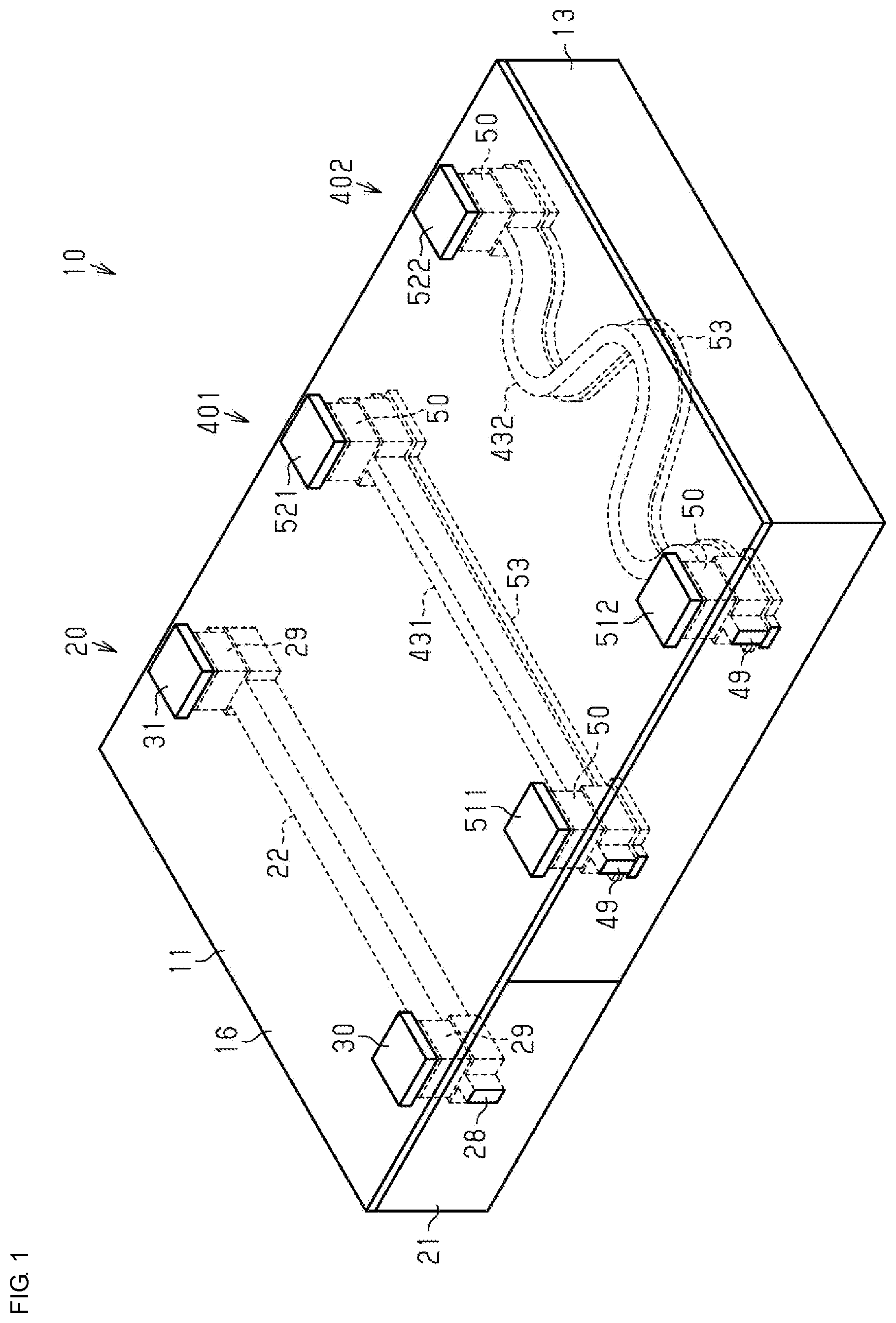
As shown in and , an inductor component 10 of the present embodiment generates a magnetic field when a current is input to the inductor component 10 . The inductor component 10 is an array component in which an air core coil 20 and magnetic core coils 401 , 402 are combined or integrated. The air core coil 20 includes an air core body 21 , and an air core inductor wire 22 provided in the air core body 21 . The magnetic core coil 401 includes a magnetic core body 411 , and a magnetic core inductor wire 431 provided in the magnetic core body 411 . The magnetic core coil 402 includes a magnetic core body 412 , and a magnetic core inductor wire 432 provided in the magnetic core body 412 . The air core body 21 and the magnetic core bodies 411 , 412 are combined or integrated. Herein, the air core coil may include a core body of the coil including low magnetic material which has magnetic properties lower than that of the magnetic material of the magnetic core coil. The core body of the coil may be made of air, alumina, glass or resin.
The phrase “combining or integrating an air core body and a magnetic core body” means any of the following three cases (A1), (A2), and (A3):
•
• (A1) The air core body and the magnetic core body are completely integrated without an interface. • (A2) There is an interface between the air core body and the magnetic core body, and the air core body and the magnetic core body are in close contact with each other. • (A3) There are boundary surfaces and a gap between the air core body and the magnetic core body, and the air core body and the magnetic core body are joined with a common different member, such as a surface layer and a substrate.
In this example, as shown in , the inductor component 10 has a substantially rectangular parallelepiped shape. Of the side surfaces of the inductor component 10 , the top surface in is referred to as a first main surface 11 of the inductor component 10 , and the undersurface in is referred to as a second main surface 12 of the inductor component 10 . The side surfaces of the inductor component 10 , other than the first main surface 11 or the second main surface 12 , are referred to as non-main surfaces 13 . In other words, the side surfaces of the inductor component 10 include the first main surface 11 , the second main surface 12 , and the non-main surfaces 13 . The shape of the inductor component 10 is not limited to a substantially rectangular parallelepiped shape and may be, for example, a substantially cylindrical shape or a substantially polygonal prism shape.
The term “main surface” is, for example, a surface having the largest area among the side surfaces of the inductor component. In this example, the areas of the top surface and the undersurface in are the largest surfaces among the side surfaces of the inductor component 10 , so the top surface and the undersurface in correspond to main surfaces. When, for example, an inductor component is mounted on a circuit board, both the side surface of the inductor component, facing the circuit board, and the side surface across inductor wires (described later) from the above side surface may be referred to as main surfaces.
In this example, as shown in , the inductor component 10 includes the one air core coil 20 and the two magnetic core coils 401 , 402 . In to , a boundary line Y indicating a boundary between the magnetic core coil 401 and the magnetic core coil 402 is represented by the alternate long and two-short dashed line. The air core coil 20 and the magnetic core coils 401 , 402 are arranged in the up-and-down direction in the drawing. In other words, in the up-and-down direction in the drawing, the air core coil 20 and the magnetic core coils 401 , 402 are arranged such that the magnetic core coil 401 is disposed between the air core coil 20 and the magnetic core coil 402 . As shown in , inductor wires 22 , 431 , 432 are disposed in a predetermined disposition plane Z 1 located between the first main surface 11 and the second main surface 12 in the up-and-down direction in the drawing. The disposition plane Z 1 may be parallel to the first main surface 11 and the second main surface 12 as shown in or may be not parallel to the first main surface 11 or the second main surface 12 .
Where an imaginary plane in which the air core inductor wire 22 is disposed is defined as a predetermined plane, the disposition plane Z 1 corresponds to the predetermined plane in this example. In this example, the magnetic core inductor wires 431 , 432 also extend along the disposition plane Z 1 in the disposition plane Z 1 . Therefore, the magnetic core inductor wires 431 , 432 extend parallel to the predetermined plane.
is a view showing a cross section when the inductor component 10 is cut along the line LN 1 indicated by the alternate long and short dashed line in . is a view showing a cross section when the inductor component 10 is cut along the line LN 2 indicated by the alternate long and short dashed line in . The line LN 2 is a line extending in the same direction as the line LN 1 . These lines LN 1 , LN 2 extend along the first main surface 11 . Therefore, in and , the right-and-left direction is a direction along the first main surface 11 , and the up-and-down direction is a direction perpendicular to the first main surface 11 .
The line LN 1 is an imaginary straight line set so as to pass through an intermediate position between a first air core outer terminal 30 (described later) and a second air core outer terminal 31 (described later) electrically connected to the air core inductor wire 22 of the air core coil 20 , an intermediate position between a first magnetic core outer terminal 511 (described later) and a second magnetic core outer terminal 521 (described later) electrically connected to the magnetic core inductor wire 431 of the magnetic core coil 401 , and an intermediate position between a first magnetic core outer terminal 512 (described later) and a second magnetic core outer terminal 522 (described later) electrically connected to the magnetic core inductor wire 432 of the magnetic core coil 402 . The line LN 2 is an imaginary straight line set at a position where a second end portion 24 (described later) of the air core inductor wire 22 of the air core coil 20 , a second end portion 451 (described later) of the magnetic core inductor wire 431 of the magnetic core coil 401 , and a second end portion 452 (described later) of the magnetic core inductor wire 432 of the magnetic core coil 402 can be cut.
The cross sections of the air core inductor wire 22 , shown in and , are cross sections when the air core inductor wire 22 is cut in a direction perpendicular to a direction in which the air core inductor wire 22 extends. More specifically, the cross section of the air core inductor wire 22 , shown in , is the cross section of the air core inductor wire 22 at an intermediate position between a first end portion 23 and the second end portion 24 of the air core inductor wire 22 (described later). The cross section of the air core inductor wire 22 , shown in , is the cross section of the second end portion 24 of the air core inductor wire 22 (described later). The cross sections of the magnetic core inductor wire 431 of the magnetic core coil 401 , shown in and , are cross sections when the magnetic core inductor wire 431 is cut in a direction perpendicular to a direction in which the magnetic core inductor wire 431 extends. More specifically, the cross section of the magnetic core inductor wire 431 , shown in , is the cross section of the magnetic core inductor wire 431 at an intermediate position between a first end portion 441 and the second end portion 451 of the magnetic core inductor wire 431 (described later). The cross section of the magnetic core inductor wire 431 , shown in , is the cross section of the second end portion 451 of the magnetic core inductor wire 431 (described later). The cross sections of the magnetic core inductor wire 432 of the magnetic core coil 402 , shown in and , are cross sections when the magnetic core inductor wire 432 is cut in a direction perpendicular to a direction in which the magnetic core inductor wire 432 extends. More specifically, the cross section of the magnetic core inductor wire 432 , shown in , is the cross section of the magnetic core inductor wire 432 at an intermediate position between a first end portion 442 and the second end portion 452 of the magnetic core inductor wire 432 (described later). The cross section of the magnetic core inductor wire 432 , shown in , is the cross section of the second end portion 452 of the magnetic core inductor wire 432 (described later).
In the cross sections of the inductor component 10 , shown in and , a direction parallel to the disposition plane Z 1 , which is the right-and-left direction in the drawing, is defined as a width direction X 1 , and a direction perpendicular to the disposition plane Z 1 , which is the up-and-down direction in the drawing, is defined as a thickness direction X 2 . In this case, the thickness direction X 2 is a direction perpendicular to the width direction X 1 . A dimension in the width direction X 1 of the air core inductor wire 22 is defined as a wire width Wa of the air core inductor wire 22 . A dimension in the thickness direction X 2 of the air core inductor wire 22 is defined as a wire thickness Ha of the air core inductor wire 22 . A dimension in the width direction X 1 of the magnetic core inductor wire 431 is defined as a wire width Wb of the magnetic core inductor wire 431 . A dimension in the thickness direction X 2 of the magnetic core inductor wire 431 is defined as a wire thickness Hb of the magnetic core inductor wire 431 . A dimension in the width direction X 1 of the magnetic core inductor wire 432 is defined as a wire width We of the magnetic core inductor wire 432 . A dimension in the thickness direction X 2 of the magnetic core inductor wire 432 is defined as a wire thickness Hc of the magnetic core inductor wire 432 .
As shown in and , the inductor component 10 includes a surface layer 16 that covers a main surface 21 a of the air core body 21 , which is the top surface of the air core body 21 of the air core coil 20 in the drawing, a main surface 411 a of the magnetic core body 411 , which is the top surface of the magnetic core body 411 of the magnetic core coil 401 in the drawing, and a main surface 412 a of the magnetic core body 412 , which is the top surface of the magnetic core body 412 of the magnetic core coil 402 in the drawing. The top surface in the drawing, which is the front surface of the surface layer 16 , corresponds to the first main surface 11 of the inductor component 10 .
The surface layer 16 is a non-magnetic electrical insulator. The electrical insulation property of the surface layer 16 is higher than the electrical insulation properties of the magnetic core bodies 411 , 412 . In the present embodiment, an electrical insulator is the one having a specific resistance of higher than or equal to about 1 MΩ·cm. A non-magnetic substance is the one made of a material having a relative magnetic permeability of about one. The surface layer 16 is made of, for example, a polyimide resin, an acrylic resin, an epoxy resin, a phenolic resin, or a liquid crystal polymer. To enhance the electrical insulation performance of the surface layer 16 , the surface layer 16 may contain an electrical insulation filler, such as a silica filler.
Next, the air core coil 20 will be described. The air core body 21 of the air core coil 20 has a non-magnetic electrically insulating layer. The air core body 21 may be made up of a single electrically insulating layer or may be a laminated body made up of a plurality of laminated electrically insulating layers. The electrically insulating layer that makes up the air core body 21 contains, for example, a polyimide resin, an acrylic resin, an epoxy resin, a phenolic resin, or a liquid crystal polymer. To enhance the electrical insulation performance of the electrically insulating layer, the electrically insulating layer may contain an electrical insulation filler, such as a silica filler.
As shown in , the air core inductor wire 22 of the air core coil 20 includes the first end portion 23 that is the left end portion of the air core inductor wire 22 in the drawing, the second end portion 24 that is the right end portion of the air core inductor wire 22 in the drawing, and a wire body 25 that connects the first end portion 23 and the second end portion 24 . In other words, the cross section of the air core inductor wire 22 , shown in , is the cross section of the wire body 25 .
The air core inductor wire 22 contains an electrically conductive material. The air core inductor wire 22 contains, for example, at least one of copper, silver, gold, and aluminum as an electrically conductive material. The air core inductor wire 22 may contain, for example, an alloy containing at least one of copper, silver, gold, and aluminum, as an electrically conductive material. As shown in and , the air core inductor wire 22 includes an air core wire seed layer 26 that is a seed layer, and an electrically conductive layer 27 disposed on the air core wire seed layer 26 . The air core wire seed layer 26 contains, for example, copper as an electrically conductive material. A dimension in the thickness direction X 2 of the air core wire seed layer 26 is less than a dimension in the thickness direction X 2 of the electrically conductive layer 27 . The air core wire seed layer 26 may further contain at least one of a layer containing titanium and a layer containing tungsten in the layer.
The electrically conductive layer 27 contains, for example, copper and sulfur. When the electrically conductive layer 27 contains copper and sulfur in this way, it is preferable that, for example, in the electrically conductive layer 27 , the ratio of copper be higher than or equal to about 99 wt % and the ratio of sulfur be higher than or equal to about 0.1 wt % and lower than about 1.0 wt % (i.e., from about 0.1 wt % to lower than about 1.0 wt %). With this configuration, good electrical conductivity of the electrically conductive layer 27 is ensured. The ratio is a ratio to the weight of the whole electrically conductive layer 27 . The air core inductor wire 22 does not need to include the air core wire seed layer 26 .
In the cross section of the wire body 25 of the air core inductor wire 22 , shown in , the wire width Wa is, for example, greater than or equal to about 90 μm and less than or equal to about 110 μm (i.e., from about 90 μm to about 110 μm). In the cross section, a dimension in the width direction X 1 between a portion located farthest to a first side (left side in the drawing) in the width direction X 1 and a portion located farthest to a second side (right side in the drawing) in the width direction X 1 in the wire body 25 is regarded as the wire width Wa of the wire body 25 in the cross section.
In the cross section of the wire body 25 of the air core inductor wire 22 , shown in , the wire thickness Ha is, for example, greater than or equal to about 35 μm and less than or equal to about 55 μm (i.e., from about 35 μm to about 55 μm). In the cross section, a dimension in the thickness direction X 2 between a portion located farthest to a first side (upper side in the drawing) in the thickness direction X 2 and a portion located farthest to a second side (lower side in the drawing) in the thickness direction X 2 in the wire body 25 is regarded as the wire thickness Ha of the wire body 25 in the cross section.
As shown in , dummy wires disposed in the predetermined disposition plane Z 1 are connected to the air core inductor wire 22 . Specifically, a dummy wire 28 connected to the first end portion 23 of the air core inductor wire 22 and a dummy wire 28 connected to the second end portion 24 of the air core inductor wire 22 are provided. These dummy wires 28 extend from connection portions with the air core inductor wire 22 to the non-main surfaces 13 of the air core body 21 . In other words, the end surfaces of the dummy wires 28 are exposed at the non-main surfaces 13 .
As shown in and , vertical wires extending from connection portions with the air core inductor wire 22 to the main surface 21 a of the air core body 21 are provided in the air core body 21 . In other words, a vertical wire 29 connected to the first end portion 23 of the air core inductor wire 22 and a vertical wire 29 connected to the second end portion 24 of the air core inductor wire 22 are provided in the air core body 21 .
The air core coil 20 includes the first air core outer terminal 30 that is a contact electrically connected to the first end portion 23 of the air core inductor wire 22 , and the second air core outer terminal 31 that is a contact electrically connected to the second end portion 24 of the air core inductor wire 22 . The first air core outer terminal 30 and the second air core outer terminal 31 are exposed at the first main surface 11 . The first air core outer terminal 30 is electrically connected to the first end portion 23 via the vertical wire 29 . The second air core outer terminal 31 is electrically connected to the second end portion 24 via the vertical wire 29 .
The air core outer terminals 30 , 31 are exposed to the outside through the surface layer 16 . The air core outer terminals 30 , 31 are in contact with both the air core body 21 and the surface layer 16 . In other words, the surface layer 16 has through-holes 16 a for exposing the main surface 21 a of the air core body 21 to the outside. The air core outer terminals 30 , 31 are formed so as to fill the through-holes 16 a . Therefore, each of the air core outer terminals 30 , 31 is in contact with all of the end surface (top surface in ) of the vertical wire 29 , the main surface 21 a of the air core body 21 , the peripheral wall of the through-hole 16 a , and the first main surface 11 .
Each of the air core outer terminals 30 , 31 is a laminated body made up of a plurality of laminated layers. The laminated body includes, for example, the following layers:
•
• (B1) A layer containing a substitutional catalyst • (B2) A layer produced by electroless plating
A method of forming a layer containing a substitutional catalyst may be, for example, a method of bringing a treatment liquid containing a substitutional catalyst into contact with the portions exposed through the through-holes 16 a in the air core body 21 and electroless copper plating layers formed on the vertical wires 29 . Thus, a surface portion of the electroless copper plating is substituted by the substitutional catalyst, for example, palladium, and a layer containing the catalyst is formed. After that, electroless nickel plating layers are further formed on the layers containing the substitutional catalyst by, for example, being immersed in a plating solution for electroless nickel plating.
An alkali catalyst process may be a method that does not use a substitutional catalyst. In this case, a catalyst (for example, lead ions) is deposited also on the surface layer 16 , and a layer containing the catalyst is formed also on the surface layer 16 . For this reason, a layer is also formed on the surface layer 16 by electroless plating. Therefore, an unnecessary layer on the surface layer 16 needs to be removed.
A layer produced by electroless plating is, for example, an electrically conductive layer in which the ratio of copper is lower than or equal to about 99 wt % and the ratio of nickel is higher than or equal to about 0.1 wt %. The ratio is a ratio to the weight of the whole layer produced by electroless plating. For example, the ratio can be calculated based on the content of each element to the whole layer produced by electroless plating. Specifically, the ratio can be calculated by analyzing the layer by using ICP. ICP is an abbreviation of inductively coupled plasma.
Next, the magnetic core coils 401 , 402 will be described. The magnetic core bodies 411 , 412 of the magnetic core coils 401 , 402 include a magnetic layer 42 . The magnetic layer 42 contains magnetic particles as a magnetic material. It is preferable that the mean particle diameter of magnetic particles contained in the magnetic layer 42 be greater than or equal to about 1 μm and less than or equal to about 5 μm (i.e., from about 1 μm to about 5 μm). The mean particle diameter is, for example, a median diameter D 50 . The magnetic material is a material having a relative magnetic permeability of greater than or equal to about one.
A method of measuring a mean particle diameter is, for example, the following method. In the cross sections of the magnetic core bodies 411 , 412 , shown in , the image of the cross section of the magnetic layer 42 containing 30 or more magnetic particles is acquired at three points different in position from one another. The images of the cross sections are acquired with an SEM (scanning electron microscope) of which the magnification is adjusted to an appropriate size (for example, 1000 times). The particle diameters of the magnetic particles are calculated based on those images as values converted from areas. A value (cumulative 50% value) located at the center among particle diameters when arranged in descending order is a mean particle diameter.
The magnetic layer 42 is made up of, for example, a resin containing metal magnetic particles. When the magnetic layer 42 is made up of a resin containing metal magnetic particles, it is desirable that the magnetic layer 42 contain at least one of iron and an alloy containing iron as metal magnetic particles.
The magnetic layer 42 may contain metal magnetic particles, other than iron-based metals, such as iron and alloys containing iron. Examples of the metal magnetic particles other than iron-based metals include nickel, chromium, copper, aluminum, and alloys of these metals. When the magnetic layer 42 contains metal magnetic particles other than iron-based metals, the magnetic layer 42 may contain magnetic particles of an iron-based metal or does not need to contain magnetic particles of an iron-based metal.
It is preferable that the magnetic layer 42 contain metal magnetic particles about 60 wt % or higher of the total weight. To enhance the fillability of a resin containing metal magnetic particles, it is more preferable that a resin contain two or three types of metal magnetic particles having different particle distributions.
A resin material, such as an epoxy resin, may be a resin for containing metal magnetic particles. In consideration of electrical insulation property and formability, it is preferable that a polyimide resin, an acrylic resin, or a phenolic resin be employed as the resin.
The magnetic layer 42 may be made up of a resin containing ferrite particles instead of metal magnetic particles or may be made up of a resin containing both metal magnetic particles and ferrite particles. Alternatively, for example, the magnetic layer 42 may be a substrate bound by sintering ferrite particles, that is, a sintered body of ferrite.
The volume of the magnetic core body 411 of the magnetic core coil 401 is different from the volume of the magnetic core body 412 of the magnetic core coil 402 . In this example, the volume of the magnetic core body 411 is greater than the volume of the magnetic core body 412 . Specifically, the dimension of the magnetic core body 411 is the same as the dimension of the magnetic core body 412 in the thickness direction X 2 shown in , and the dimension of the magnetic core body 411 is the same as the dimension of the magnetic core body 412 in a direction perpendicular to both the width direction X 1 shown in and the thickness direction X 2 shown in ; however, the dimension of the magnetic core body 411 is greater than the dimension of the magnetic core body 412 in the width direction X 1 shown in . By varying the volume in this way, even when the constituent materials of the magnetic core bodies are the same and the contents of the magnetic materials in the magnetic core bodies are the same, the magnetic permeability of the magnetic core coil 401 can be varied from the magnetic permeability of the magnetic core coil 402 . Of course, the volume of the magnetic core body 411 may be the same as the volume of the magnetic core body 412 .
As shown in , the magnetic core inductor wire 431 of the magnetic core coil 401 includes the first end portion 441 that is the left end portion of the magnetic core inductor wire 431 in the drawing, the second end portion 451 that is the right end portion of the magnetic core inductor wire 431 in the drawing, and a wire body 461 that connects the first end portion 441 and the second end portion 451 . In other words, the cross section of the magnetic core inductor wire 431 , shown in , is the cross section of the wire body 461 . In this example, as shown in , the first end portion 441 is disposed at the same position as the first end portion 23 of the air core inductor wire 22 in the right-and-left direction in the drawing. The second end portion 451 is disposed at the same position as the second end portion 24 of the air core inductor wire 22 in the right-and-left direction in the drawing.
The magnetic core inductor wire 432 of the magnetic core coil 402 includes the first end portion 442 disposed at the same position as the first end portion 441 of the magnetic core inductor wire 431 in the right-and-left direction in , the second end portion 452 disposed at the same position as the second end portion 451 of the magnetic core inductor wire 431 in the right-and-left direction in , and a wire body 462 that connects the first end portion 442 and the second end portion 452 . In other words, the cross section of the magnetic core inductor wire 432 , shown in , is the cross section of the wire body 462 . The wire body 462 extends from a connection portion with the first end portion 442 to a connection portion with the second end portion 452 while meandering. For this reason, the line length of the magnetic core inductor wire 432 is greater than any of the line length of the magnetic core inductor wire 431 and the line length of the air core inductor wire 22 .
Each of the magnetic core inductor wires 431 , 432 contains an electrically conductive material. Each of the magnetic core inductor wires 431 , 432 contains, for example, at least one of copper, silver, gold, and aluminum as an electrically conductive material. Each of the magnetic core inductor wires 431 , 432 may contain, for example, an alloy containing at least one of copper, silver, gold, and aluminum, as an electrically conductive material. As shown in and , each of the magnetic core inductor wires 431 , 432 includes a magnetic core wire seed layer 47 that is a seed layer, and an electrically conductive layer 48 disposed on the magnetic core wire seed layer 47 . The magnetic core wire seed layer 47 contains, for example, copper as an electrically conductive material. A dimension in the thickness direction X 2 of the magnetic core wire seed layer 47 is less than a dimension in the thickness direction X 2 of the electrically conductive layer 48 . The magnetic core wire seed layer 47 may further contain at least one of a layer containing titanium and a layer containing tungsten in the layer.
The electrically conductive layer 48 contains, for example, copper and sulfur. When the electrically conductive layer 48 contains copper and sulfur in this way, the ratio of copper may be higher than or equal to about 99 wt % and the ratio of sulfur may be higher than or equal to about 0.1 wt % and lower than about 1.0 wt % in the electrically conductive layer 48 , for example. The ratio is a ratio to the weight of the whole electrically conductive layer 48 . Each of the magnetic core inductor wires 431 , 432 does not need to include the magnetic core wire seed layer 47 .
In the cross section of the wire body 461 of the magnetic core inductor wire 431 , shown in , the wire width Wb is, for example, greater than or equal to about 40 μm and less than or equal to about 60 μm (i.e., from about 40 μm to about 60 μm). In the cross section, a dimension in the width direction X 1 between a portion located farthest to a first side (left side in the drawing) in the width direction X 1 and a portion located farthest to a second side (right side in the drawing) in the width direction X 1 in the wire body 461 is regarded as the wire width Wb of the wire body 461 in the cross section.
In the cross section of the wire body 461 of the magnetic core inductor wire 431 , shown in , the wire thickness Hb is, for example, greater than or equal to about 35 μm and less than or equal to about 55 μm (i.e., from about 35 μm to about 55 μm). In the cross section, a dimension in the thickness direction X 2 between a portion located farthest to a first side (upper side in the drawing) in the thickness direction X 2 and a portion located farthest to a second side (lower side in the drawing) in the thickness direction X 2 in the wire body 461 is regarded as the wire thickness Hb of the wire body 461 in the cross section.
In the cross section of the wire body 462 of the magnetic core inductor wire 432 , shown in , the wire width Wc is, for example, greater than or equal to about 40 μm and less than or equal to about 60 μm (i.e., from about 40 μm to about 60 μm). In the cross section, a dimension in the width direction X 1 between a portion located farthest to a first side (left side in the drawing) in the width direction X 1 and a portion located farthest to a second side (right side in the drawing) in the width direction X 1 in the wire body 462 is regarded as the wire width Wc of the wire body 462 in the cross section.
In the cross section of the wire body 462 of the magnetic core inductor wire 432 , shown in , the wire thickness Hc is, for example, greater than or equal to about 35 μm and less than or equal to about 55 μm (i.e., from about 35 μm to about 55 μm). In the cross section, a dimension in the thickness direction X 2 between a portion located farthest to a first side (upper side in the drawing) in the thickness direction X 2 and a portion located farthest to a second side (lower side in the drawing) in the thickness direction X 2 in the wire body 462 is regarded as the wire thickness Hc of the wire body 462 in the cross section.
As shown in , the magnetic core coil 401 includes dummy wires 49 connected to the magnetic core inductor wire 431 , and the magnetic core coil 402 includes dummy wires 49 connected to the magnetic core inductor wire 432 . The dummy wires 49 extend from connection portions with the magnetic core inductor wires 431 , 432 to the non-main surfaces 13 of the magnetic core bodies 411 , 412 . In this example, the dummy wire 49 connected to the first end portion 441 of the magnetic core inductor wire 431 , the dummy wire 49 connected to the first end portion 442 of the magnetic core inductor wire 432 , the dummy wire 49 connected to the second end portion 451 of the magnetic core inductor wire 431 , and the dummy wire 49 connected to the second end portion 452 of the magnetic core inductor wire 432 are provided. These dummy wires 49 extend from the connection portions with the magnetic core inductor wires 431 , 432 to the non-main surfaces 13 of the magnetic core bodies 411 , 412 . In other words, the end surfaces of the dummy wires 49 are exposed at the non-main surfaces 13 .
As shown in and , vertical wires extending from connection portions with the magnetic core inductor wire 431 toward the main surface 411 a of the magnetic core body 411 are provided in the magnetic core body 411 , and vertical wires extending from connection portions with the magnetic core inductor wire 432 toward the main surface 412 a of the magnetic core body 412 are provided in the magnetic core body 412 . In other words, a vertical wire 50 connected to the first end portion 441 of the magnetic core inductor wire 431 and a vertical wire 50 connected to the second end portion 451 of the magnetic core inductor wire 431 are provided in the magnetic core body 411 , and a vertical wire 50 connected to the first end portion 442 of the magnetic core inductor wire 432 and a vertical wire 50 connected to the second end portion 452 of the magnetic core inductor wire 432 are provided in the magnetic core body 412 .
The magnetic core coil 401 includes the first magnetic core outer terminal 511 that is an outer terminal electrically connected to the first end portion 441 of the magnetic core inductor wire 431 and the second magnetic core outer terminal 521 that is an outer terminal electrically connected to the second end portion 451 of the magnetic core inductor wire 431 . The magnetic core coil 402 includes the first magnetic core outer terminal 512 that is an outer terminal electrically connected to the first end portion 442 of the magnetic core inductor wire 432 and the second magnetic core outer terminal 522 that is an outer terminal electrically connected to the second end portion 452 of the magnetic core inductor wire 432 . The first magnetic core outer terminals 511 , 512 and the second magnetic core outer terminals 521 , 522 are exposed at the first main surface 11 . The first magnetic core outer terminal 511 is electrically connected to the first end portion 441 via the vertical wire 50 . The first magnetic core outer terminal 512 is electrically connected to the first end portion 442 via the vertical wire 50 . The second magnetic core outer terminal 521 is electrically connected to the second end portion 451 via the vertical wire 50 . The second magnetic core outer terminal 522 is electrically connected to the second end portion 452 via the vertical wire 50 .
The magnetic core outer terminals 511 , 512 , 521 , 522 are exposed to the outside through the surface layer 16 . The magnetic core outer terminals 511 , 521 are in contact with both the magnetic core body 411 and the surface layer 16 . The magnetic core outer terminals 512 , 522 are in contact with both the magnetic core body 412 and the surface layer 16 . In other words, the surface layer 16 has through-holes 16 b for exposing the main surfaces 411 a , 412 a of the magnetic core bodies 411 , 412 to the outside. The magnetic core outer terminals 511 , 512 , 521 , 522 are formed so as to fill the through-holes 16 b . Therefore, each of the magnetic core outer terminals 511 , 521 is in contact with all of the end surface (top surface in ) of the vertical wire 50 , the main surface 411 a of the magnetic core body 411 , the peripheral wall of the through-hole 16 b , and the first main surface 11 , and each of the magnetic core outer terminals 512 , 522 is in contact with all of the end surface (top surface in ) of the vertical wire 50 , the main surface 412 a of the magnetic core body 412 , the peripheral wall of the through-hole 16 b , and the first main surface 11 .
Each of the magnetic core outer terminals 511 , 512 , 521 , 522 is a laminated body made up of a plurality of laminated layers. The laminated body includes, for example, layers as described in (B1) and (B2). In this example, as shown in to , an electrically insulating layer 53 that is in contact with the magnetic core inductor wire 431 and the dummy wires 49 is provided in the magnetic core body 411 , and an electrically insulating layer 53 that is in contact with the magnetic core inductor wire 432 and the dummy wires 49 is provided in the magnetic core body 412 . Each of the electrically insulating layers 53 is disposed between the first main surface 11 and the second main surface 12 of the inductor component 10 . More specifically, the electrically insulating layer 53 is disposed between the magnetic core inductor wire 431 and the second main surface 12 , and the electrically insulating layer 53 is disposed between the magnetic core inductor wire 432 and the second main surface 12 . In other words, as shown in and , the undersurfaces of the magnetic core inductor wire 431 and the dummy wires 49 in the drawing are in contact with the electrically insulating layer 53 , and the undersurfaces of the magnetic core inductor wire 432 and the dummy wires 49 in the drawing are in contact with the electrically insulating layer 53 . On the other hand, the top surfaces of the magnetic core inductor wire 431 and the dummy wires 49 in the drawing are not in contact with the electrically insulating layer 53 , and the top surfaces of the magnetic core inductor wire 432 and the dummy wires 49 in the drawing are not in contact with the electrically insulating layer 53 .
Each of the electrically insulating layers 53 is a non-magnetic electrical insulator. Each of the electrically insulating layers 53 is made of, for example, a polyimide resin, an acrylic resin, an epoxy resin, a phenolic resin, or a liquid crystal polymer. To enhance the electrical insulation performance of each of the electrically insulating layers 53 , each of the electrically insulating layers 53 may contain an electrical insulation filler, such as a silica filler.
Next, a boundary portion between the air core body 21 and the magnetic core body 411 will be described. is an enlarged diagram of a portion surrounded by the dashed line in . As shown in and , the air core body 21 and the magnetic core body 411 are contiguous to each other. At a boundary portion between the air core body 21 and the magnetic core body 411 , part of magnetic particles P contained in the magnetic core body 411 may be embedded in the air core body 21 . In such a case, an interface between the air core body 21 and the magnetic core body 411 has an irregular shape as shown in . The air core body 21 and the magnetic core body 411 may be in contact with each other in such a mode in which a boundary between the air core body 21 and the magnetic core body 411 contiguous to each other cannot be identified. In and , the magnetic core body 411 and the magnetic core body 412 are in contact with each other in such a mode in which a boundary between the magnetic core body 411 and the magnetic core body 412 cannot be identified. Not limited to this mode, the magnetic core body 411 and the magnetic core body 412 may be in contact with each other in such a mode in which a boundary between the magnetic core body 411 and the magnetic core body 412 can be identified.
Next, the definition of an air core coil provided in an air core body and the definition of a magnetic core coil provided in a magnetic core body will be described. is a cross-sectional view when the inductor component 10 is cut along the line LN 1 shown in . The cross section shown in is a cross section of the inductor component 10 in a direction perpendicular to any of the inductor wires 22 , 431 , 432 . In other words, is a predetermined cross section of the inductor component 10 , taken along the direction perpendicular to the direction in which the air core inductor wire 22 extends. In addition, is a predetermined cross section of the inductor component 10 , taken along the direction perpendicular to the direction in which the magnetic core inductor wire 431 extends. In addition, is a predetermined cross section of the inductor component 10 , taken along the direction perpendicular to the direction in which the magnetic core inductor wire 432 extends.
In this example, there is a portion where directions in which the three inductor wires 22 , 431 , 432 extend are parallel to one another. However, there may be no portion where directions in which the three inductor wires 22 , 431 , 432 extend are parallel to one another. In such a case, the predetermined cross section of each of the inductor wires 22 , 431 , 432 cannot be acquired through a single cross section of the inductor component 10 . Thus, the predetermined cross section of each of the inductor wires 22 , 431 , 432 is acquired by individually cutting the inductor component 10 for each of the inductor wires 22 , 431 , 432 .
In the cross section of the inductor component 10 , shown in , a region surrounding each inductor wire is set as a peripheral region F. Each peripheral region F is a portion obtained by removing a wiring portion from a region surrounded by a first straight line B 1 , a second straight line B 2 , a third straight line B 3 , and a fourth straight line B 4 . The wiring portion is a portion provided in the air core body 21 or the magnetic core body 411 and through which a current flows. In other words, in the present embodiment, the wiring portions include the inductor wires 22 , 431 , 432 and the vertical wires 29 , 50 . On the other hand, the wiring portions do not contain magnetic particles. The first straight line B 1 and the second straight line B 2 are imaginary straight lines extending in the thickness direction X 2 . The third straight line B 3 and the fourth straight line B 4 are imaginary straight lines extending in the width direction X 1 . More specifically, when the wire width of the wire body of each inductor wire in is the wire width of the inductor wire, the first straight line B 1 is a line passing through a portion spaced the wire width of the inductor wire apart in the width direction X 1 from a first end (left end in the drawing) in the width direction X 1 of the inductor wire in the cross section shown in . The second straight line B 2 is a line passing through a portion spaced the wire width of the inductor wire apart in the width direction X 1 from a second end (right end in the drawing) in the width direction X 1 of the inductor wire in the cross section shown in . When the wire thickness of the wire body of each inductor wire in is the wire thickness of the inductor wire, the third straight line B 3 is a line passing through a portion spaced the wire thickness of the inductor wire apart in the thickness direction X 2 from a first end (upper end in the drawing) in the thickness direction X 2 of the inductor wire in the cross section shown in . The fourth straight line B 4 is a line passing through a portion spaced the wire thickness of the inductor wire apart in the thickness direction X 2 from a second end (lower end in the drawing) in the thickness direction X 2 of the inductor wire in the cross section shown in .
When the content of magnetic material in the peripheral region F is defined as a magnetic material content Ra, an inductor of which the magnetic material content Ra is lower than about 50% is defined as an air core coil. An inductor of which the magnetic material content Ra is higher than or equal to about 50% is defined as a magnetic core coil. A value obtained by setting the sum of the area of a non-magnetic electrical insulator and the area of a portion containing a magnetic material in the peripheral region F is a denominator and the area of a portion containing a magnetic material is a numerator is derived as magnetic material content Ra.
Here, an example of a method of measuring a magnetic material content Ra will be described. When the magnetic material is fine particles, the cross section of the inductor component 10 , including the peripheral region F, is taken with an SEM of which the magnification is adjusted to an appropriate size (for example, 1000 times). Subsequently, the total area of a large number of fine particles in the cross section is derived as the area of the portion containing a magnetic material. Then, a value obtained by setting the whole area of the peripheral region F for a denominator and setting the derived area of the portion containing a magnetic material for a numerator is derived as magnetic material content Ra.
The magnetic material may not be fine particles. For example, a sintered body of ferrite can be a magnetic material. In this case, the whole of the sintered body is a magnetic material, so the area of the sintered body in the peripheral region F is derived as the area of a portion containing a magnetic material.
shows a portion obtained by removing the air core inductor wire 22 from a region surrounded by a first straight line B 1 A, a second straight line B 2 A, a third straight line B 3 A, and a fourth straight line B 4 A as a peripheral region FA for the air core inductor wire 22 . A portion obtained by removing the magnetic core inductor wire 431 from a region surrounded by a first straight line B 1 B, a second straight line B 2 B, a third straight line B 3 B, and a fourth straight line B 4 B is shown as a peripheral region FB for the magnetic core inductor wire 431 . A portion obtained by removing the magnetic core inductor wire 432 from a region surrounded by a first straight line B 1 C, a second straight line B 2 C, a third straight line B 3 C, and a fourth straight line B 4 C is shown as a peripheral region FC for the magnetic core inductor wire 432 . As shown in , the area of the cross section of the air core inductor wire 22 is the greatest of the inductor wires 22 , 431 , 432 . Therefore, the area of the peripheral region FA is the greatest of the peripheral regions FA, FB, FC.
The magnetic material content Ra is lower than about 50% in the peripheral region FA shown in . Specifically, the magnetic material content Ra is about 0%. The magnetic material content Ra is higher than or equal to about 50% in the peripheral region FB shown in . Specifically, the magnetic material content Ra is about 95%. The magnetic material content Ra is higher than or equal to about 50% in the peripheral region FC shown in . Specifically, the magnetic material content Ra is about 95%.
The peripheral region F may extend off the cross section of the inductor component 10 depending on the installation position or shape of the inductor wire. When part of the peripheral region F extends off the cross section of the inductor component 10 , the magnetic material content Ra is derived by excluding a portion extending off the cross section from the peripheral region F.
is a cross-sectional view of the inductor component 10 including the second end portions 24 , 451 , 452 of the inductor wires 22 , 431 , 432 . More specifically, the cross section shown in is a cross section when the inductor component 10 is cut along the direction perpendicular to the direction in which the air core inductor wire 22 extends. The cross section shown in is a cross section when the inductor component 10 is cut along the direction perpendicular to the direction in which the magnetic core inductor wire 431 extends. The cross section shown in is a cross section when the inductor component 10 is cut along the direction perpendicular to the direction in which the magnetic core inductor wire 432 extends. In other words, shows a predetermined cross section including the second end portion 24 of the air core inductor wire 22 . In addition, shows a predetermined cross section including the second end portion 451 of the magnetic core inductor wire 431 . In addition, shows a predetermined cross section including the second end portion 452 of the magnetic core inductor wire 432 .
shows a portion obtained by removing the air core inductor wire 22 and the vertical wire 29 from a region surrounded by the first straight line B 1 A, the second straight line B 2 A, the third straight line B 3 A, and the fourth straight line B 4 A as the peripheral region FA around the second end portion 24 of the air core inductor wire 22 . A portion obtained by removing the magnetic core inductor wire 431 and the vertical wire 50 from a region surrounded by the first straight line B 1 B, the second straight line B 2 B, the third straight line B 3 B, and the fourth straight line B 4 B is shown as the peripheral region FB around the second end portion 451 of the magnetic core inductor wire 431 . A portion obtained by removing the magnetic core inductor wire 432 and the vertical wire 50 from a region surrounded by the first straight line B 1 C, the second straight line B 2 C, the third straight line B 3 C, and the fourth straight line B 4 C is shown as the peripheral region FC around the second end portion 452 of the magnetic core inductor wire 432 .
The magnetic material content Ra is lower than about 50% in the peripheral region FA shown in . Specifically, the magnetic material content Ra is about 0%. The magnetic material content Ra is higher than or equal to about 50% in the peripheral region FB shown in . Specifically, the magnetic material content Ra is about 95%. The magnetic material content Ra is higher than or equal to about 50% in the peripheral region FC shown in . Specifically, the magnetic material content Ra is about 95%. The magnetic material content Ra in the peripheral region FA shown in does not need to be about 0% as long as the magnetic material content Ra is lower than about 50%. The magnetic material content Ra in the peripheral region FB shown in does not need to be about 95% as long as the magnetic material content Ra is higher than or equal to about 50%. The magnetic material content Ra in the peripheral region FC shown in does not need to be about 95% as long as the magnetic material content Ra is higher than or equal to about 50%.
Incidentally, as in the case shown in , a peripheral region FA around the first end portion 23 of the air core inductor wire 22 may be set in the cross section of the inductor component 10 , taken by cutting the first end portion 23 of the air core inductor wire 22 . A peripheral region FB around the first end portion 441 of the magnetic core inductor wire 431 may be set in the cross section of the inductor component 10 , taken by cutting the first end portion 441 of the magnetic core inductor wire 431 . A peripheral region FC around the first end portion 442 of the magnetic core inductor wire 432 may be set in the cross section of the inductor component 10 , taken by cutting the first end portion 442 of the magnetic core inductor wire 432 . The magnetic material content Ra in the peripheral region FA around the first end portion 23 is lower than about 50%. Specifically, the magnetic material content Ra is about 0%. The magnetic material content Ra in the peripheral region FB around the first end portion 441 is higher than or equal to about 50%. Specifically, the magnetic material content Ra is about 95%. The magnetic material content Ra in the peripheral region FC around the first end portion 442 is higher than or equal to about 50%. Specifically, the magnetic material content Ra is about 95%.
The magnetic core coils 401 , 402 in the present embodiment have the following characteristics. In the magnetic core coil 401 , when the frequency of inductor current LC input to the magnetic core inductor wire 431 is higher than or equal to about 1 MHz and lower than or equal to about 50 MHz (i.e., from about 1 MHz to about 50 MHz), the effective magnetic permeability is higher than or equal to about three. In the magnetic core coil 402 , when the frequency of inductor current LC input to the magnetic core inductor wire 432 is higher than or equal to about 1 MHz and lower than or equal to about 50 MHz (i.e., from about 1 MHz to about 50 MHz), the effective magnetic permeability is higher than or equal to about three. The inductor current LC is a current flowing through an inductor wire.
The effective magnetic permeability is a magnetic permeability that can be derived from an effective self-inductance in a magnetic core in which leakage flux can be ignored. In other words, the effective magnetic permeability is a magnetic permeability that can be derived from self-inductance. The inductance of a magnetic core coil is measured with, for example, an impedance analyzer or a network analyzer. At this time, a small signal (current) input to the magnetic core coil is a direct-current bias sufficiently small to such an extent that the magnetic core coil is not magnetically saturated. The inductance is measured by sweeping the frequency of the small signal from about 1 MHz to about 50 MHz. Subsequently, an actual measured value of the inductance and a simulated value of the inductance are adjusted by structural simulation of the magnetic core coil. Thus, the overall magnetic permeability of the magnetic core coil, obtained by smoothing the influence of local density of magnetic material, or the like, can be obtained as the effective magnetic permeability of the magnetic core coil.
Next, the difference in characteristics among the air core coil 20 , the magnetic core coil 401 , and the magnetic core coil 402 in the present embodiment will be described. The range of inductor current LC in which magnetic saturation does not occur in any of the magnetic core coils 401 , 402 is referred to as low current range ALC. In this case, when the magnitude of inductor current LC falls within the low current range ALC, magnetic saturation does not occur in the magnetic core coil 401 , so the inductance of the magnetic core coil 401 is greater than the inductance of the air core coil 20 . Similarly, when the magnitude of inductor current LC falls within the low current range ALC, magnetic saturation does not occur in the magnetic core coil 402 , so the inductance of the magnetic core coil 402 is greater than the inductance of the air core coil 20 . On the other hand, when the magnitude of inductor current LC is greater than the upper limit of the low current range ALC, magnetic saturation may occur in the magnetic core coil 401 or the magnetic core coil 402 . When magnetic saturation occurs in the magnetic core coil 401 , the inductance of the magnetic core coil 401 is less than the inductance of the air core coil 20 . Similarly, when magnetic saturation occurs in the magnetic core coil 402 , the inductance of the magnetic core coil 402 is less than the inductance of the air core coil 20 .
The direct current electric resistance of the air core coil 20 is lower than the direct current electric resistance of the magnetic core coil 401 and is lower than the direct current electric resistance of the magnetic core coil 402 . Specifically, the line length of the air core inductor wire 22 is equal to the line length of the magnetic core inductor wire 431 . On the other hand, as shown in , the area of the cross section of the air core inductor wire 22 when the air core inductor wire 22 is cut in the direction perpendicular to the direction in which the air core inductor wire 22 extends is greater than the area of the cross section of the magnetic core inductor wire 431 when the magnetic core inductor wire 431 is cut in the direction perpendicular to the direction in which the magnetic core inductor wire 431 extends. With this configuration, the direct current electric resistance of the air core coil 20 is made lower than the direct current electric resistance of the magnetic core coil 401 .
The line length of the air core inductor wire 22 is less than the line length of the magnetic core inductor wire 432 . As shown in , the area of the cross section of the air core inductor wire 22 when the air core inductor wire 22 is cut in the direction perpendicular to the direction in which the air core inductor wire 22 extends is greater than the area of the cross section of the magnetic core inductor wire 432 when the magnetic core inductor wire 432 is cut in the direction perpendicular to the direction in which the magnetic core inductor wire 432 extends. With this configuration, the direct current electric resistance of the air core coil 20 is made lower than the direct current electric resistance of the magnetic core coil 402 .
The line length of the magnetic core inductor wire 431 is less than the line length of the magnetic core inductor wire 432 . As shown in , the area of the cross section of the magnetic core inductor wire 431 when the magnetic core inductor wire 431 is cut in the direction perpendicular to the direction in which the magnetic core inductor wire 431 extends is equal to the area of the cross section of the magnetic core inductor wire 432 when the magnetic core inductor wire 432 is cut in the direction perpendicular to the direction in which the magnetic core inductor wire 432 extends. With this configuration, the direct current electric resistance of the magnetic core inductor wire 431 is made lower than the direct current electric resistance of the magnetic core coil 402 . When, of the magnetic core coils 401 , 402 , the magnetic core coil having a lower direct current electric resistance is defined as a first magnetic core coil and the magnetic core coil having a higher direct current electric resistance is defined as a second magnetic core coil, the magnetic core coil 401 having the magnetic core inductor wire 431 corresponds to the first magnetic core coil, and the magnetic core coil 402 having the magnetic core inductor wire 432 corresponds to the second magnetic core coil.
The line length of the magnetic core inductor wire 431 is different from the line length of the magnetic core inductor wire 432 , so the inductance of the magnetic core coil 401 is different from the inductance of the magnetic core coil 402 . When, of the magnetic core coils 401 , 402 , the magnetic core coil having a greater inductance is defined as a first magnetic core coil and the magnetic core coil having a less inductance is defined as a second magnetic core coil, the magnetic core coil having a greater inductance corresponds to the first magnetic core coil, and the magnetic core coil having a less inductance corresponds to the second magnetic core coil.
Next, a DC-DC converter 80 on which the inductor component 10 is mounted will be described with reference to . The DC-DC converter 80 includes a switching circuit 82 . In the DC-DC converter 80 , an input signal (direct current) from a direct-current power supply 81 is input to the inductor component 10 via the switching circuit 82 . The switching circuit 82 includes switching elements 82 a , 82 b , 82 c as many as the inductor wires 22 , 431 , 432 in the inductor component 10 . The switching elements 82 a , 82 b , 82 c are disposed in parallel with one another. In other words, of the switching elements 82 a , 82 b , 82 c , an input signal flows from the direct-current power supply 81 to only the inductor electrically connected to the switching element turned on. For example, MOS-FET circuits may be the switching elements 82 a , 82 b , 82 c . Examples of the MOS-FET circuit include the one including two FETs and the one including a MOS-FET and a diode. The MOS-FET circuit including two FETs can be made up of two FETs and a controller 83 .
Then, an inductor current LC flows through the electrically connected one of the switching elements 82 a , 82 b , 82 c to an associated one of the inductor wires 22 , 431 , 432 of the inductor component 10 .
The DC-DC converter 80 includes the controller 83 that controls the on/off state of each of the switching elements 82 a , 82 b , 82 c in accordance with the magnitude of current output from the inductor component 10 . In other words, one of the inductor wires 22 , 431 , 432 for passing the inductor current LC is selected by the controller 83 .
Assuming that a switching element electrically connected to an air core coil is defined as an air core switching element and a switching element electrically connected to a magnetic core coil is defined as a magnetic core switching element. In this case, the switching element 82 a corresponds to the air core switching element, and the switching elements 82 b , 82 c correspond to the magnetic core switching elements.
Then, when a load current to the inductor component 10 is less than or equal to a first load current determination value, the controller 83 turns off the switching element 82 a for the air core coil, and turns on a first switching element and turns off a second switching element of the switching elements 82 b , 82 c for the magnetic core coils. Thus, a current flows through one of the magnetic core coil 401 and the magnetic core coil 402 , having a greater inductance than the air core coil 20 . On the other hand, when a load current to the inductor component 10 exceeds the first load current determination value, the controller 83 turns on the switching element 82 a and turns off the switching elements 82 b , 82 c . Thus, a current flows through the air core coil 20 having a better direct-current superposition characteristic than the magnetic core coils 401 , 402 . In other words, when the magnitude of a load current based on which whether a load is high is determined is defined as a predetermined current, the first load current determination value corresponds to the predetermined current.
In the present embodiment, the inductor component 10 includes the two magnetic core coils 401 , 402 . Then, it is assumed that the inductance of the magnetic core coil 402 is less than the inductance of the magnetic core coil 401 and the direct current electric resistance of the magnetic core coil 402 is higher than the direct current electric resistance of the magnetic core coil 401 . In this case, when a load current is less than or equal to a second load current determination value less than the first load current determination value, the switching element 82 c is preferably turned on and the switching elements 82 a , 82 b are preferably turned off. Thus, a current can be passed through the magnetic core coil 402 having a low inductance and an intermediate direct current electric resistance. When a load current is greater than the second load current determination value and less than or equal to the first load current determination value, the switching elements 82 a , 82 c are preferably turned off, and the switching element 82 b is preferably turned on. Thus, a current can be passed through the magnetic core coil 401 having an intermediate inductance and a low direct current electric resistance. When a load current exceeds the first load current determination value, the switching elements 82 b , 82 c are preferably turned off, and the switching element 82 a is preferably turned on. Thus, a current can be passed through the air core coil 20 having a high inductance and a high direct current electric resistance. By using the three inductors in this way, the inductance acquisition efficiency of the inductor component 10 is enhanced.
In the present embodiment, the following operation and advantageous effects are obtained.
(1-1) The inductor component 10 includes not only the magnetic core coils 401 , 402 but also the air core coil 20 having a higher magnetic saturation current than the magnetic core coils 401 , 402 . For this reason, in the DC-DC converter 80 in which a current to be input to the inductor component 10 is relatively large, the magnetic core coils 401 , 402 and the air core coil 20 are used according to the magnitude of a load current, with the result that the DC-DC converter 80 is appropriately operated. Therefore, while the inductor having a high inductance acquisition efficiency is provided, it is possible to support a large current.
(1-2) With the magnetic core coils 401 , 402 , when the frequency of inductor current LC is higher than or equal to about 1 MHz and lower than or equal to about 50 MHz (i.e., from about 1 MHz to about 50 MHz), the effective magnetic permeability is higher than or equal to about three. Such a frequency range provides switching frequencies to be used in a radio-frequency DC-DC converter for, for example, supplying power to a CPU or a GPU. Therefore, when the magnetic core coils 401 , 402 are configured as described above, the inductor component 10 can be made as an inductor component suitable for a DC-DC converter for a CPU or a GPU.
(1-3) The inductance of each of the magnetic core coils 401 , 402 is greater than the inductance of the air core coil 20 , so the inductance acquisition efficiency of each of the magnetic core coils 401 , 402 is higher than the inductance acquisition efficiency of the air core coil 20 . When the inductor component 10 includes the magnetic core coils having a high inductance acquisition efficiency in this way, the inductance acquisition efficiency is increased while an increase in the size of the inductor component 10 is suppressed. More specifically, the areas of the first main surface 11 and the second main surface 12 can be reduced. As a result, in mounting the inductor component 10 on a circuit board, it is easy to ensure an installation location for the inductor component 10 on the circuit board.
(1-4) In the DC-DC converter 80 , when a load current that is a current flowing to a load side is relatively large, a lower direct current electric resistance is given a higher priority than a greater inductance as the performance desired for an inductor component. In the present embodiment, in the above case, the direct current electric resistance of the air core coil 20 is lower than the direct current electric resistance of each of the magnetic core coils 401 , 402 . For this reason, in the case where the inductor component 10 is used in the DC-DC converter 80 , when a load current is large, a current is passed through the air core coil 20 in which magnetic saturation is less likely to occur. With this configuration, the function of the inductor component 10 can be more easily exercised by the amount by which a decrease in inductance is suppressed.
(1-5) In the present embodiment, the inductor component 10 includes a plurality of inductors, that is, the air core coil 20 and the magnetic core coils 401 , 402 . For this reason, the inductance of the inductor component 10 can be set to an appropriate value according to a load current at that time by changing the inductor through which a current is passed or changing the number of inductors through which a current is passed according to the magnitude of the load current. Thus, the efficiency of the DC-DC converter 80 is enhanced.
(1-6) In the present embodiment, the inductor wires 22 , 431 , 432 are disposed in the predetermined disposition plane Z 1 . For this reason, in comparison with the case where the position in the thickness direction X 2 of a part of the inductor wires 22 , 431 , 432 is different from the positions in the thickness direction X 2 of the remaining inductor wires, an increase in the dimension of the inductor component 10 in the thickness direction X 2 is suppressed. Therefore, the inductor component 10 is made as an inductor component suitable for a circuit of which component mounting efficiency improves by means of three-dimensional mounting, for example, a circuit around a CPU or a GPU.
(1-7) As shown in , a direct distance NA from the first air core outer terminal 30 to the second air core outer terminal 31 in the air core coil 20 , a direct distance NB from the first magnetic core outer terminal 511 to the second magnetic core outer terminal 521 in the magnetic core coil 401 , and a direct distance NC from the first magnetic core outer terminal 512 to the second magnetic core outer terminal 522 in the magnetic core coil 402 are equal to one another. Thus, in comparison with the case where a part of the direct distances NA, NB, NC differs from the remaining direct distances, the inductor component 10 can be more easily mounted on a circuit board.
The direct distance between a pair of outer terminals is a distance from the center of a first outer terminal to the center of a second outer terminal of the pair of outer terminals in the first main surface 11 of the inductor component 10 . The pair of outer terminals is two outer terminals electrically connected to an inductor wire.
(1-8) By varying the volumes of the magnetic core bodies 411 , 412 from each other, both a magnetic core coil having a high magnetic permeability and a low direct-current superposition characteristic and a magnetic core coil having a low magnetic permeability and a high direct-current superposition characteristic can be provided in the inductor component 10 even with the same magnetic material and composition ratio.
(1-9) When the disposition plane Z 1 is parallel to the first main surface 11 , it is possible to suppress long direct distances from the inductor wires 22 , 431 , 432 to the outer terminals 30 , 31 , 511 , 521 , 512 , 522 .
(1-10) The inductor component 10 includes the surface layer 16 . Thus, oxidation of a metal material contained in the magnetic core bodies 411 , 412 is suppressed.
(1-11) When the inductor component 10 in which the air core coil 20 and the magnetic core coils 401 , 402 are combined or integrated is used in the DC-DC converter 80 , the number of components of the DC-DC converter 80 is reduced as compared to when the air core coil 20 and the magnetic core coils 401 , 402 are individually provided in the DC-DC converter 80 . As a result, an increase in the size of the DC-DC converter 80 is suppressed. In addition, mounting one component results in mounting a plurality of inductors. Therefore, in comparison with the case where a plurality of inductors is individually mounted, the number of man-hours needed for mounting components is reduced.
(1-12) When the inductor component 10 is used in the DC-DC converter 80 , the inductor through which a current is passed can be selected from between the magnetic core coil 401 and the magnetic core coil 402 not under high load. Therefore, it is possible to expand the range of power supply circuits that can be supported by the inductor component 10 and, by extension, to increase the flexibility of design of a power supply circuit.
Next, an example of a manufacturing method for the above-described inductor component 10 will be described with reference to to . The manufacturing method described here is a method using a semiadditive process to form the inductor wires 22 , 431 , 432 .
As shown in , in the first step, a first manufacturing electrically insulating layer 105 is formed on a substrate 100 . The substrate 100 has a substantially sheet shape. The material of the substrate 100 may be, for example, ceramic. In , the top surface of the substrate 100 is defined as a front surface 101 , and the undersurface of the substrate 100 is defined as a back surface 102 . The first manufacturing electrically insulating layer 105 is formed on the substrate 100 to cover the whole front surface 101 of the substrate 100 . The first manufacturing electrically insulating layer 105 is made of the same non-magnetic material as the electrically insulating layer 53 and the air core body 21 that are components of the inductor component 10 . The first manufacturing electrically insulating layer 105 may be formed by, for example, applying polyimide varnish containing trifluoromethyl group and silsesquioxane onto the front surface 101 of the substrate 100 by spin coating.
When formation of the first manufacturing electrically insulating layer 105 completes, the next step starts. In this step, a second manufacturing electrically insulating layer 110 is formed on the first manufacturing electrically insulating layer 105 . As will be described in detail later, part of the second manufacturing electrically insulating layer 110 becomes the electrically insulating layers 53 of the magnetic core coils 401 , 402 . The second manufacturing electrically insulating layer 110 may be formed by, for example, applying polyimide varnish containing trifluoromethyl group and silsesquioxane onto the first manufacturing electrically insulating layer 105 by spin coating.
When formation of the second manufacturing electrically insulating layer 110 completes, the next step starts. In this step, the second manufacturing electrically insulating layer 110 is subjected to working as shown in . Part of the second manufacturing electrically insulating layer 110 is removed by, for example, photolithography. In the example shown in , in the second manufacturing electrically insulating layer 110 , a portion where the air core body 21 of the air core coil 20 is formed, a portion caused to function as the electrically insulating layer 53 of the magnetic core coil 401 , and a portion caused to function as the electrically insulating layer 53 of the magnetic core coil 401 are left, and the other portion is removed.
Photolithography will be described. Initially, a photoresist is applied onto the second manufacturing electrically insulating layer 110 by spin coating. Subsequently, exposure is performed by using an exposure apparatus. Thus, in the photoresist, a portion covering a removal object portion in the second manufacturing electrically insulating layer 110 can be removed through a development process (described later), and the other portion is cured. When a negative-type resist is employed as a photoresist, an exposed portion of the photoresist is cured and the other portion can be removed. On the other hand, when a positive-type resist is employed as a photoresist, an exposed portion of the photoresist can be removed and the other portion is cured. By controlling a portion to be exposed in a photoresist, part of a portion stuck on the second manufacturing electrically insulating layer 110 can be cured. Subsequently, the removal object portion in the photoresist is removed through a development process using a developer. Then, the cured portion in the photoresist is left as a protective film. A pattern is formed by patterning a protective film in this way. The pattern has an open shape corresponding to the shape of the removal object portion. Subsequently, the exposed portion, that is, a portion not covered with the protective film, in the second manufacturing electrically insulating layer 110 is removed by wet etching. After that, the protective film is removed through a process using a stripper solution.
When working of the second manufacturing electrically insulating layer 110 completes, the next step starts. In this step, a seed layer 115 is formed. In other words, as shown in , the seed layer 115 is formed so as to cover the exposed portion of the first manufacturing electrically insulating layer 105 and the whole top surface of the second manufacturing electrically insulating layer 110 in the drawing. The seed layer 115 containing copper is formed by, for example, sputtering. For example, the seed layer 115 with a thickness of about 200 nm is formed. As will be described in detail later, part of the seed layer 115 becomes the air core wire seed layer 26 . Another part becomes the magnetic core wire seed layer 47 .
When formation of the seed layer 115 completes, the next step starts. In this step, a first protective film 120 is formed as shown in . A photoresist is applied to the seed layer 115 by, for example, spin coating. Subsequently, exposure is performed by using an exposure apparatus. Thus, in the photoresist, portions corresponding to positions where the inductor wires 22 , 431 , 432 are formed can be removed through a development process (described later), and the other portion is cured. Subsequently, as shown in , portions corresponding to positions where the inductor wires 22 , 431 , 432 are formed in the photoresist are removed through a development process using a developer. The cured portion of the photoresist is left as the first protective film 120 . A wiring pattern PT 1 is formed by patterning the first protective film 120 in this way. The wiring pattern PT 1 has opening shapes corresponding to the shapes of the inductor wires 22 , 431 , 432 .
When formation of the wiring pattern PT 1 completes, the next step starts. In this step, the electrically conductive layers 27 , 48 as shown in are formed by supplying an electrically conductive material into the wiring pattern PT 1 . Copper and a small amount of sulfur mainly precipitate on the exposed portion of the seed layer 115 by, for example, performing electrolytic copper plating using a copper sulfate solution. Thus, the electrically conductive layers 27 , 48 are formed. Since a copper sulfate solution is used, sulfur is contained in the electrically conductive layers 27 , 48 . The inductor wire 22 is made up of the electrically conductive layer 27 and a portion with which the electrically conductive layer 27 contacts in the seed layer 115 . Each of the inductor wires 431 , 432 is made up of the electrically conductive layer 48 and a portion with which the electrically conductive layer 48 contacts in the seed layer 115 . In other words, in the seed layer 115 , the portion with which the electrically conductive layer 27 contacts becomes the air core wire seed layer 26 , and the portions with which the electrically conductive layers 48 contact become the magnetic core wire seed layers 47 .
When formation of the electrically conductive layers 27 , 48 completes, the first protective film 120 is removed as shown in through a process using a stripper solution. When removal of the first protective film 120 completes, a portion that has been in contact with the first protective film 120 in the seed layer 115 is removed. The portion that has been in contact with the first protective film 120 in the seed layer 115 is removed by, for example, wet etching. In other words, portions other than the portions that become the air core wire seed layer 26 or the magnetic core wire seed layers 47 in the seed layer 115 are removed.
In the next step, a second protective film 125 is formed as shown in . In other words, a photoresist is applied so as to hide the inductor wires 22 , 431 , 432 . A photoresist is applied by, for example, spin coating. Subsequently, exposure is performed by using an exposure apparatus. Thus, in the photoresist, portions corresponding to positions where the vertical wires 29 , 50 are formed can be removed through a development process (described later), and the other portion is cured. Subsequently, in the photoresist, non-cured portions are removed and the cured portions are left as the second protective film 125 through a development process using a developer. Thus, a vertical pattern that is a pattern for forming the vertical wires 29 , 50 is formed.
When formation of the vertical pattern completes, the next step starts. In the next step, the vertical wires 29 , 50 are formed as shown in . An electrically conductive material is supplied into the vertical pattern by, for example, performing electrolytic copper plating using a copper sulfate solution, with the result that the vertical wires 29 , 50 are formed. In this case, when the inductor wires 22 , 431 , 432 are supplied with electric power via the dummy wires 28 , 49 , copper that is an electrically conductive material is supplied into the vertical pattern. When a copper sulfate solution is used in this way, a small amount of sulfur is contained in the vertical wires 29 , 50 . When formation of the vertical wires 29 , 50 completes, the second protective film 125 is removed as shown in through a process using a stripper solution.
When removal of the second protective film 125 completes, the next step starts. In this step, a third manufacturing electrically insulating layer 130 that covers the inductor wires 22 , 431 , 432 as shown in is formed by applying the same non-magnetic electrically insulating material as the second manufacturing electrically insulating layer 110 by spin coating or the like. Part of the third manufacturing electrically insulating layer 130 becomes the air core body 21 of the air core coil 20 .
Subsequently, as shown in , portions that cover the magnetic core inductor wires 431 , 432 in the third manufacturing electrically insulating layer 130 are removed. Portions that cover the magnetic core inductor wires 431 , 432 in the third manufacturing electrically insulating layer 130 can be removed by, for example, photolithography. Removal of the portions may be performed by using a laser for scraping the portions instead of photolithography.
When the magnetic core inductor wires 431 , 432 are exposed through such a process, the next step starts. In this step, a manufacturing magnetic layer 136 is formed by pressing a magnetic sheet 135 from the upper side in . At this time, the manufacturing magnetic layer 136 may be formed by laminating a plurality of magnetic sheets 135 in the up-and-down direction in the drawing. When the manufacturing magnetic layer 136 is formed, the magnetic core inductor wires 431 , 432 and the third manufacturing electrically insulating layer 130 are covered with the manufacturing magnetic layer 136 as shown in .
When formation of the manufacturing magnetic layer 136 completes, the next step starts. In this step, the manufacturing magnetic layer 136 and the third manufacturing electrically insulating layer 130 are ground. As shown in , grounding is performed until the end surfaces (top surfaces in the drawing) of the vertical wires 29 , 50 are exposed. A remaining portion in the third manufacturing electrically insulating layer 130 functions as the magnetic layer 42 of the magnetic core bodies 411 , 412 .
When grinding completes, the next step starts. In this step, the surface layer 16 is formed on the top surfaces of the third manufacturing electrically insulating layer 130 and the magnetic layer 42 in the drawing, as shown in . In other words, the top surface of the third manufacturing electrically insulating layer 130 in the drawing becomes the main surface 21 a of the air core body 21 of the air core coil 20 . Of the top surface of the magnetic layer 42 in the drawing, the left-side portion in the drawing becomes the main surface 411 a of the magnetic core body 411 of the magnetic core coil 401 , and the right-side portion in the drawing becomes the main surface 412 a of the magnetic core body 412 of the magnetic core coil 402 . The surface layer 16 is formed by, for example, applying a non-magnetic electrically insulating resin. In this state, the vertical wires 29 , 50 are also covered with the surface layer 16 . Then, the through-holes 16 a , 16 b are formed at positions where the outer terminals 30 , 31 , 511 , 512 , 521 , 522 are formed in the surface layer 16 . The through-holes 16 a , 16 b can be formed by, for example, applying a laser beam to the surface layer 16 . When the surface layer 16 is formed, the surface layer 16 may be formed by patterning a non-magnetic electrically insulating resin on the top surface in the drawing by using photolithography. In this case, the surface layer 16 having the through-holes 16 a , 16 b can be formed by photolithography, so a step of forming the through-holes 16 a , 16 b by using a laser can be omitted.
When formation of the surface layer 16 completes, the next step starts. In this step, as shown in , the substrate 100 and the first manufacturing electrically insulating layer 105 are removed by grinding. Grinding is performed until the magnetic layer 42 appears.
When grinding completes, the next step starts. In this step, as shown in , a fourth manufacturing electrically insulating layer 140 is formed by photolithography. The fourth manufacturing electrically insulating layer 140 is in contact with the undersurface of the third manufacturing electrically insulating layer 130 in the drawing but is not in contact with the undersurface of the magnetic layer 42 in the drawing. The air core body 21 of the air core coil 20 is formed by the third manufacturing electrically insulating layer 130 and the fourth manufacturing electrically insulating layer 140 .
When formation of the air core body 21 completes, the next step starts. In this step, as shown in , the magnetic core body 411 of the magnetic core coil 401 and the magnetic core body 412 of the magnetic core coil 402 are formed by pressing a magnetic sheet 145 against the magnetic layer 42 .
When formation of the magnetic core bodies 411 , 412 completes, the next step starts. In this step, the air core body 21 , the magnetic core body 411 , and the magnetic core body 412 are combined or integrated by thermal curing. When the bodies 21 , 411 , 412 are combined or integrated, the next step starts. In this step, as shown in , the outer terminals 30 , 31 , 511 , 512 , 521 , 522 are formed. Thus, a series of steps that compose the manufacturing method for the inductor component 10 ends.
The above-described manufacturing method is an example of the case where the inductor component 10 is manufactured one by one. However, the manufacturing method for the inductor component 10 is not limited thereto. For example, portions to be a plurality of inductor components 10 may be disposed in a matrix on the substrate 100 , and diced by a dicer after the end of a step of forming the outer terminals 30 , 31 , 511 , 512 , 521 , 522 . A curing step, such as heating, may be performed as needed after applying a non-magnetic electrically insulating resin or after pressing a magnetic sheet. A step of combining or integrating the bodies 21 , 411 , 412 may be performed after a step of forming the outer terminals 30 , 31 , 511 , 512 , 521 , 522 , or the bodies 21 , 411 , 412 may be combined or integrated by thermal curing in the middle of each step.
Second Embodiment
Next, a second embodiment of an inductor component will be described with reference to . In the following description, portions different from the first embodiment will be mainly described, like reference signs denote the same or corresponding components to those of the first embodiment, and the description will not be repeated.
As shown in , in an inductor component 10 A of the present embodiment, an air core coil 20 A includes a first vertical wire 29 A that is a vertical wire extending from a connection portion with the air core inductor wire 22 toward the first main surface 11 , and a second vertical wire 32 A that is a vertical wire extending from the connection portion to the second main surface 12 . In other words, of both end surfaces of the second vertical wire 32 A, the end surface exposed at the second main surface 12 is an air core outer terminal 34 that is an outer terminal. shows the air core outer terminal 34 electrically connected to the second end portion 24 of the air core inductor wire 22 ; however, there is also an air core outer terminal 34 electrically connected to the first end portion 23 of the air core inductor wire 22 . When the outer terminal exposed at the second main surface 12 and electrically connected to the air core inductor wire 22 is defined as a third air core outer terminal, the air core outer terminal 34 corresponds to the third air core outer terminal.
A magnetic core coil 401 A includes a first vertical wire 50 A that is a vertical wire extending from a connection portion with the magnetic core inductor wire 431 toward the first main surface 11 , and a second vertical wire 54 A extending from the connection portion to the second main surface 12 . A magnetic core coil 402 A includes a first vertical wire 50 A that is a vertical wire extending from a connection portion with the magnetic core inductor wire 432 toward the first main surface 11 , and a second vertical wire MA extending from the connection portion to the second main surface 12 . In other words, of both end surfaces of the second vertical wire MA, the end surface exposed at the second main surface 12 is a magnetic core outer terminal 561 or a magnetic core outer terminal 562 that is an outer terminal. shows the magnetic core outer terminal 561 electrically connected to the second end portion 451 of the magnetic core inductor wire 431 , and the magnetic core outer terminal 562 electrically connected to the second end portion 452 of the magnetic core inductor wire 432 ; however, there are also a magnetic core outer terminal 561 electrically connected to the first end portion 441 of the magnetic core inductor wire 431 and a magnetic core outer terminal 562 eclectically connected to the first end portion 442 of the magnetic core inductor wire 432 . When the outer terminal exposed to the second main surface 12 and electrically connected to the magnetic core inductor wire 431 is defined as a third magnetic core outer terminal, the magnetic core outer terminal 561 corresponds to the third magnetic core outer terminal. When the outer terminal exposed to the second main surface 12 and electrically connected to the magnetic core inductor wire 432 is defined as a third magnetic core outer terminal, the magnetic core outer terminal 562 corresponds to the third magnetic core outer terminal.
Each second vertical wire 54 A extends through the electrically insulating layer 53 . In other words, each second vertical wire 54 A has a via 54 a extending through the electrically insulating layer 53 , and a columnar wire 54 b connected to the via 54 a.
According to the present embodiment, in addition to advantageous effects equivalent to (1-1) to (1-11), the following advantageous effect is further obtained.
(2-1) In mounting the inductor component 10 A on a circuit board, the inductor component 10 A can be mounted such that the first main surface 11 faces the circuit board or the inductor component 10 A may be mounted such that the second main surface 12 faces the circuit board. In other words, in mounting the inductor component 10 A on a circuit board, the mounting flexibility is enhanced.
Third Embodiment
Next, a third embodiment of an inductor component will be described with reference to to . In the following description, portions different from the first embodiment will be mainly described, like reference signs denote the same or corresponding components to those of the first embodiment, and the description will not be repeated.
As shown in , in an inductor component 10 B of the present embodiment, an air core body 21 B of an air core coil 20 B includes an electrically insulating layer 33 a and a magnetic layer 33 b that are laminated along the thickness direction X 2 . Specifically, in the thickness direction X 2 , the electrically insulating layer 33 a and the magnetic layer 33 b are laminated such that the electrically insulating layer 33 a is located between the surface layer 16 and the magnetic layer 33 b . The air core inductor wire 22 is provided in the electrically insulating layer 33 a . In this case, the electrically insulating layer 33 a is a non-magnetic electrical insulator. The magnetic layer 33 b contains a magnetic material. The magnetic layer 33 b is made up of, for example, a resin containing metal magnetic particles.
In the present embodiment, the air core inductor wire 22 is disposed in the electrically insulating layer 33 a . In the peripheral region FA around the air core inductor wire 22 , the magnetic material content Ra is lower than about 50%, with the result that the air core coil 20 is provided in the inductor component 10 B.
In the inductor component 10 B, a magnetic core body 411 B of a magnetic core coil 401 B includes a first magnetic layer 42 a and a second magnetic layer 42 b laminated along the thickness direction X 2 . In addition, a magnetic core body 412 B of a magnetic core coil 402 B, as well as the magnetic core body 411 B, includes a first magnetic layer 42 a and a second magnetic layer 42 b laminated along the thickness direction X 2 . Specifically, in the thickness direction X 2 , the first magnetic layer 42 a and the second magnetic layer 42 b are laminated such that the first magnetic layer 42 a is located between the surface layer 16 and the second magnetic layer 42 b . The magnetic core inductor wire 431 is provided in the first magnetic layer 42 a . The magnetic core inductor wire 432 is provided in the first magnetic layer 42 a.
The first magnetic layer 42 a contains a magnetic material not contained in the second magnetic layer 42 b . For example, the first magnetic layer 42 a may contain iron-based magnetic particles, such as iron and alloys containing iron, and the second magnetic layer 42 b may contain another magnetic material, other than iron-based magnetic particles. The second magnetic layer 42 b is, for example, a substrate bound by sintering ferrite particles, that is, a sintered body of ferrite particles. The second magnetic layer 42 b may be a resin containing non-iron-based magnetic particles. In such a case, the second magnetic layer 42 b does not contain iron-based magnetic particles. A magnetic material contained in the second magnetic layer 42 b may be the same as a magnetic material contained in the first magnetic layer 42 a.
In the present embodiment, the magnetic core inductor wire 431 and the vertical wires 50 are provided in the first magnetic layer 42 a in a state of being covered with an electrically insulating film 53 B all around. The electrically insulating film 53 B is exceedingly thin. For this reason, in the peripheral region FB around the magnetic core inductor wire 431 , the magnetic material content Ra is higher than or equal to about 50%. On the other hand, the magnetic core inductor wire 432 is not covered with the electrically insulating film 53 B. For this reason, in the peripheral region FC around the magnetic core inductor wire 432 as well, the magnetic material content Ra is higher than or equal to about 50%. Thus, the magnetic core coils 401 B, 402 B can be provided in the inductor component 10 B.
In the present embodiment, the magnetic layer 33 b of the air core body 21 B, the second magnetic layer 42 b of the magnetic core body 411 B, and the second magnetic layer 42 b of the magnetic core body 412 B contain the same magnetic material. Alternatively, the second magnetic layer 42 b of the magnetic core body 411 B may contain a magnetic material not contained in any of the magnetic layer 33 b of the air core body 21 B and the second magnetic layer 42 b of the magnetic core body 412 B. Alternatively, the magnetic layer 33 b of the air core body 21 B may contain a magnetic material not contained in any of the second magnetic layer 42 b of the magnetic core body 411 B and the second magnetic layer 42 b of the magnetic core body 412 B. Alternatively, the magnetic layer 42 b of the magnetic core body 412 B may contain a magnetic material not contained in any of the magnetic layer 33 b of the air core body 21 B and the second magnetic layer 42 b of the magnetic core body 411 B.
According to the present embodiment, in addition to advantageous effects equivalent to (1-1) to (1-12), the following advantageous effect is further obtained.
(3-1) A laminated body of a plurality of magnetic layers containing different magnetic materials is used as the magnetic core bodies 411 B, 412 B, so the magnetic permeability and direct-current superposition characteristic of each of the magnetic core coils 401 B, 402 B are more easily set to an appropriate magnitude.
Next, part of an example of a manufacturing method for the inductor component 10 B will be described with reference to and . The manufacturing method is similar to the manufacturing method described in the first embodiment until the third manufacturing electrically insulating layer 130 that covers the inductor wires 22 , 431 , 432 is formed. In the next step after formation of the third manufacturing electrically insulating layer 130 , part of the third manufacturing electrically insulating layer 130 is removed as shown in . Specifically, a portion that makes up the air core body 21 B of the air core coil 20 B and a portion that makes up the electrically insulating film 53 B that covers the magnetic core inductor wire 431 and vertical wires 50 of the magnetic core coil 401 B are left, and the other portion is removed.
In the next step, as shown in , the first magnetic layer 42 a of the magnetic core body 411 B of the magnetic core coil 401 B is formed. In other words, a first magnetic sheet 135 A for forming the first magnetic layer 42 a is pressed against the substrate 100 . Subsequently, the first magnetic layer 42 a of the magnetic core body 412 B of the magnetic core coil 402 B is formed. In other words, a second magnetic sheet 135 B for forming the first magnetic layer 42 a is pressed against the substrate 100 .
After that, the electrically insulating layer 33 a of the air core body 21 B and the first magnetic layers 42 a of the magnetic core coils 401 B, 402 B are formed by grinding. After that, the substrate 100 and the first manufacturing electrically insulating layer 105 are removed by grinding. In this state, the magnetic layer 33 b of the air core body 21 B and the second magnetic layers 42 b of the magnetic core coils 401 B, 402 B are formed. When the substrate 100 is a sintered body of ferrite, the substrate 100 can be formed into the electrically insulating layer 33 a of the air core body 21 B and the first magnetic layers 42 a of the magnetic core coils 401 B, 402 B, so the substrate 100 does not need to be removed.
Fourth Embodiment
Next, a fourth embodiment of an inductor component will be described with reference to to . In the following description, portions different from the first embodiment will be mainly described, like reference signs denote the same or corresponding components to those of the first embodiment, and the description will not be repeated.
is a cross-sectional view of an inductor component 10 C of the present embodiment. is a view showing a cross section when the inductor component 10 C is cut along the line LN 3 indicated by the alternate long and short dashed line in . is a view showing a cross section when the inductor component 10 C is cut along the line LN 4 indicated by the alternate long and short dashed line in . The line LN 4 is an imaginary straight line parallel to the line LN 3 .
As shown in and , the inductor component 10 C is an array component in which an air core coil and magnetic core coils are combined or integrated. In this example, as shown in , the inductor component 10 C includes two magnetic core coils 401 C, 402 C and one air core coil 20 C. The magnetic core coils 401 C, 402 C and the air core coil 20 C are arranged in the up-and-down direction in the drawing. In other words, in the up-and-down direction in the drawing, the magnetic core coils 401 C, 402 C and the air core coil 20 C are arranged such that the magnetic core coil 402 C is disposed between the magnetic core coil 401 C and the air core coil 20 C. Thus, a magnetic core body 412 C of the magnetic core coil 402 C is in contact with any of a magnetic core body 411 C of the magnetic core coil 401 C and an air core body 21 C of the air core coil 20 C. In the magnetic core coil 401 C, a magnetic core inductor wire 431 C is provided in the magnetic core body 411 C. In the magnetic core coil 402 C, a magnetic core inductor wire 432 C is provided in the magnetic core body 412 C. In the air core coil 20 C, an air core inductor wire 22 C is provided in the air core body 21 C. As shown in , the inductor wires 431 C, 432 C, 22 C are disposed in the predetermined disposition plane Z 1 located between the first main surface 11 and the second main surface 12 in the up-and-down direction in the drawing.
The line LN 3 is an imaginary straight line set so as to pass through an intermediate position between the first air core outer terminal 30 and the second air core outer terminal 31 electrically connected to the air core inductor wire 22 C of the air core coil 20 C, an intermediate position between the first magnetic core outer terminal 511 and the second magnetic core outer terminal 521 electrically connected to the magnetic core inductor wire 431 C of the magnetic core coil 401 C, and an intermediate position between the first magnetic core outer terminal 512 and the second magnetic core outer terminal 522 electrically connected to the magnetic core inductor wire 432 C of the magnetic core coil 402 C. The line LN 4 is an imaginary straight line set at a position where a second end portion 24 C of the air core inductor wire 22 C, a second end portion 451 C of the magnetic core inductor wire 431 C, and a second end portion 452 C of the magnetic core inductor wire 432 C can be cut.
In the present embodiment, the magnetic core body 411 C of the magnetic core coil 401 C has a magnetic layer, and the magnetic core body 412 C of the magnetic core coil 402 C has a magnetic layer. The magnetic layer is configured such that the magnetic material content Ra is higher than or equal to about 50% in the peripheral region F around the magnetic core inductor wire 431 C and the magnetic material content Ra is higher than or equal to about 50% in the peripheral region F around the magnetic core inductor wire 432 C. For this reason, the inductor component 10 C including the magnetic core coils is provided. The air core body 21 C of the air core coil 20 C has an electrically insulating layer. The electrically insulating layer is configured such that the magnetic material content Ra in the peripheral region F around the air core inductor wire 22 C is lower than about 50%. For this reason, the inductor component 10 C including the air core coil is provided.
The volume of the magnetic core body 411 C of the magnetic core coil 401 C is different from the volume of the magnetic core body 412 C of the magnetic core coil 402 C. In this example, as shown in to , the volume of the magnetic core body 411 C is greater than the volume of the magnetic core body 412 C. The volume of the magnetic core body 411 C may be the same as the volume of the magnetic core body 412 C or may be less than the volume of the magnetic core body 412 C.
As shown in , the magnetic core inductor wire 431 C extends in the right-and-left direction in the drawing in the magnetic core coil 401 C. Similarly, the magnetic core inductor wire 432 C extends in the right-and-left direction in the drawing in the magnetic core coil 402 C. In the magnetic core inductor wire 431 C, the vertical wire 50 is connected to a first end portion 441 C that is the left end portion in the drawing, and the vertical wire 50 is connected to a second end portion 451 C that is the right end portion in the drawing. In the magnetic core inductor wire 432 C, the vertical wire 50 is connected to a first end portion 442 C that is the left end portion in the drawing, and the vertical wire 50 is connected to a second end portion 452 C that is the right end portion in the drawing. The magnetic core inductor wire 431 C includes a wire body 461 C that connects the first end portion 441 C and the second end portion 451 C. The magnetic core inductor wire 432 C includes a wire body 462 C that connects the first end portion 442 C and the second end portion 452 C. In this example, as shown in , the area of the cross section of the wire body 461 C of the magnetic core inductor wire 431 C is greater than the area of the cross section of the wire body 462 C of the magnetic core inductor wire 432 C.
The magnetic core coil 401 C includes the first magnetic core outer terminal 511 electrically connected to the first end portion 441 C of the magnetic core inductor wire 431 C via the vertical wire 50 , and the second magnetic core outer terminal 521 electrically connected to the second end portion 451 C of the magnetic core inductor wire 431 C via the vertical wire 50 . The magnetic core coil 402 C includes the first magnetic core outer terminal 512 electrically connected to the first end portion 442 C of the magnetic core inductor wire 432 C via the vertical wire 50 , and the second magnetic core outer terminal 522 electrically connected to the second end portion 452 C of the magnetic core inductor wire 432 C via the vertical wire 50 . A direct distance NA 1 from the first magnetic core outer terminal 511 to the second magnetic core outer terminal 521 in the magnetic core coil 401 C is equal to a direct distance NB 1 from the first magnetic core outer terminal 512 to the second magnetic core outer terminal 522 in the magnetic core coil 402 C.
The air core inductor wire 22 C of the air core coil 20 C includes a first end portion 23 C disposed at the same position as the first end portions 441 C, 442 C of the magnetic core inductor wires 431 C, 432 C in the right-and-left direction in , a second end portion 24 C disposed at the same position as the second end portions 451 C, 452 C of the magnetic core inductor wires 431 C, 432 C in the right-and-left direction in , and a wire body 25 C that connects the first end portion 23 C and the second end portion 24 C. The wire body 25 C extends from a connection portion with the first end portion 23 C to a connection portion with the second end portion 24 C while meandering. For this reason, the line length of the air core inductor wire 22 C is greater than the line length of each of the magnetic core inductor wires 431 C, 432 C. In this example, as shown in , the area of the cross section of the wire body 25 C of the air core inductor wire 22 C is equivalent to the area of the cross section of the wire body 462 C of the magnetic core inductor wire 432 C and is less than the area of the cross section of the wire body 461 C of the magnetic core inductor wire 431 C. With this configuration, the direct current electric resistance of the air core coil 20 C is made higher than the direct current electric resistance of each of the magnetic core coils 401 C, 402 C.
The air core coil 20 C includes the first air core outer terminal 30 electrically connected to the first end portion 23 C of the air core inductor wire 22 C via the vertical wire 29 , and the second air core outer terminal 31 electrically connected to the second end portion 24 C of the air core inductor wire 22 C via the vertical wire 29 . A direct distance NC 1 from the first air core outer terminal 30 to the second air core outer terminal 31 in the air core coil 20 C is equal to each of the direct distances NA 1 , NB 1 .
With the above configuration, in addition to advantageous effects equivalent to (1-1), (1-2), and (1-4) to (1-12), the following advantageous effect is further obtained.
(4-1) In the present embodiment, the direct current electric resistance of the air core coil 20 C is higher than the direct current electric resistance of each of the magnetic core coils 401 C, 402 C. Although the inductance of the air core coil 20 C is less than the inductance of each of the magnetic core coils 401 C, 402 C, the inductance of the air core coil 20 C can be relatively increased. For this reason, when the inductor component 10 C is used in the DC-DC converter 80 , the inductance of the inductor component 10 C can be increased at the time of passing a current through the air core coil 20 C. As a result, the efficiency of the DC-DC converter 80 at the time of passing a current through the air core coil 20 C is enhanced.
Fifth Embodiment
Next, a fifth embodiment of an inductor component will be described with reference to to . In the following description, portions different from the first embodiment will be mainly described, like reference signs denote the same or corresponding components to those of the first embodiment, and the description will not be repeated.
is a plan view showing an inductor component 10 D of the present embodiment. is a view showing a cross section when the inductor component 10 D is cut along the line LN 5 indicated by the alternate long and short dashed line in . is a view showing a cross section when the inductor component 10 D is cut along the line LN 6 indicated by the alternate long and short dashed line in . The line LN 6 is an imaginary straight line perpendicular to the line LN 5 . In and , the up-and-down direction in the drawing is the thickness direction X 2 . A direction in which the line LN 5 extends and that is the right-and-left direction in is defined as the width direction X 1 .
The inductor component 10 D is an array inductor component in which a plurality of air core coils 201 D, 202 D and one magnetic core coil 40 D are combined or integrated. As shown in and , the air core coils 201 D, 202 D and the magnetic core coil 40 D are disposed at different positions in the thickness direction X 2 . In this example, the air core coils 201 D, 202 D are located on a first side in the thickness direction X 2 , which is the upper side in the drawing, and the magnetic core coil 40 D is located on a second side in the thickness direction X 2 , which is the lower side in the drawing.
As shown in , first air core outer terminals 301 D, 302 D and second air core outer terminals 311 D, 312 D of the air core coils 201 D, 202 D and a first magnetic core outer terminal 51 D and second magnetic core outer terminal 52 D of the magnetic core coil 40 D are exposed at the first main surface 11 of the inductor component 10 D. The first air core outer terminals 301 D, 302 D and the first magnetic core outer terminal 51 D are located on a first side (left side in the drawing) of the center in the right-and-left direction in the drawing, and the second air core outer terminals 311 D, 312 D and the second magnetic core outer terminal 52 D are located on a second side (right side in the drawing) of the center in the right-and-left direction in the drawing. In the up-and-down direction in the drawing, the air core outer terminals 301 D, 311 D of the air core coil 201 D are located on the uppermost side, the air core outer terminals 302 D, 312 D of the air core coil 202 D are located in the middle, and the magnetic core outer terminals 51 D, 52 D of the magnetic core coil 40 D are located on the lowermost side.
A direct distance from the first air core outer terminal 301 D to the second air core outer terminal 311 D in the air core coil 201 D is defined as a first air core direct distance, and a direct distance from the first air core outer terminal 302 D to the second air core outer terminal 312 D in the air core coil 202 D is defined as a second air core direct distance. A direct distance from the first magnetic core outer terminal 51 D to the second magnetic core outer terminal 52 D in the magnetic core coil 40 D is defined as a magnetic core direct distance. In this case, the first air core direct distance, the second air core direct distance, and the magnetic core direct distance are equal to one another. A direct distance is, of a pair of electrically connected outer terminals, the length of a straight line connecting the center of a first outer terminal and the center of a second outer terminal.
In this example, the second main surface 12 of the inductor component 10 D is made up of a surface layer 16 D that is a non-magnetic electrical insulator. In other words, in the thickness direction X 2 , the surface layer 16 D is disposed on the side across the magnetic core coil 40 D from the air core coils 201 D, 202 D.
The inductor component 10 D includes a magnetic portion 61 D and an electrically insulating portion 62 D disposed along the thickness direction X 2 . The magnetic portion 61 D and the electrically insulating portion 62 D are disposed such that the magnetic portion 61 D is located between the surface layer 16 D and the magnetic portion 61 D. The magnetic portion 61 D may be a laminated body in which a plurality of magnetic layers is laminated in the thickness direction X 2 or may be made up of a single magnetic layer. Similarly, the electrically insulating portion 62 D may be a laminated body in which a plurality of electrically insulating layers is laminated in the thickness direction X 2 or may be made up of a single electrically insulating layer.
When a portion that has magnetism and in which the magnetic core inductor wire 43 D is provided is defined as a magnetic core body, the magnetic portion 61 D corresponds to the magnetic core body. When a portion that is a non-magnetic electrical insulator and in which an air core inductor wire is provided is defined as an air core body, the electrically insulating portion 62 D includes both the air core body of the air core coil 201 D and the air core body of the air core coil 202 D.
The magnetic core inductor wire 43 D includes a first end portion 44 D electrically connected to the first magnetic core outer terminal MD, a second end portion 45 D electrically connected to the second magnetic core outer terminal 52 D, and a wire body 46 D connecting the first end portion 44 D and the second end portion 45 D. The wire body 46 D extends along a predetermined magnetic core plane Z 2 . In other words, in the present embodiment, the magnetic core plane Z 2 corresponds to a predetermined plane. As shown in and , the wire body 46 D has a substantially spiral shape about a central axis Si of the inductor component 10 D shown in in the predetermined magnetic core plane Z 2 . When viewed from above, the wire body 46 D is wound in a substantially spiral shape in the counterclockwise direction in the drawing from the radially outer first end portion 44 D toward the radially inner second end portion 45 D.
The number of turns of the inductor wire is determined in accordance with an imaginary vector. The starting point of the imaginary vector is placed in an imaginary center line extending through the center of the inductor wire in the wire width in a direction in which the inductor wire extends. When the imaginary vector is viewed in the thickness direction X 2 , the imaginary vector is tangent to the imaginary center line extending in the direction in which the inductor wire extends. When the starting point of the imaginary vector is moved from a state where the starting point is placed at one end of the imaginary center line to the other end of the imaginary center line, the number of turns is determined as “1.0 turn” when the angle of rotation of the orientation of the imaginary vector is 360°. Therefore, when, for example, wound 180°, the number of turns is 0.5.
Incidentally, in this example, the number of turns of the wire body 46 D of the magnetic core inductor wire 43 D is greater than or equal to about three. As shown in , and , an electrically insulating film 53 D that is in contact with the magnetic core inductor wire 43 D is provided in the magnetic portion 61 D. The electrically insulating film 53 D may be omitted.
The air core inductor wire 221 D of the air core coil 201 D includes a first end portion 231 D electrically connected to the first air core outer terminal 301 D, a second end portion 241 D electrically connected to the second air core outer terminal 311 D, and a wire body 251 D connecting the first end portion 231 D and the second end portion 241 D. The wire body 251 D extends parallel to the magnetic core plane Z 2 . In this example, as shown in , the wire body 251 D extends in the right-and-left direction in the drawing. In other words, the number of turns of the air core inductor wire 221 D is less than the number of turns of the magnetic core inductor wire 43 D of the magnetic core coil 40 D. More specifically, the number of turns of the air core inductor wire 221 D is less than about 1.0.
The inductor wire 222 D of the air core coil 202 D includes a first end portion 232 D electrically connected to the first air core outer terminal 302 D, a second end portion 242 D electrically connected to the second air core outer terminal 312 D, and a wire body 252 D connecting the first end portion 232 D and the second end portion 242 D. The wire body 252 D extends parallel to the magnetic core plane Z 2 . The wire body 252 D includes a first body portion 25 a connected to the first end portion 232 D, a second body portion 25 b connected to the first body portion 25 a , and a third body portion 25 c connected to the second body portion 25 b and the second end portion 242 D. The first body portion 25 a approaches from a connection portion with the first end portion 232 D to the air core inductor wire 221 D in the up-and-down direction in the drawing, leaves away from the inductor wire 221 D, and connects with the second body portion 25 b . The second body portion 25 b extends in a direction away from the air core inductor wire 221 D (downward in the drawing) in the up-and-down direction in the drawing from a connection portion with the first body portion 25 a , approaches to the air core inductor wire 221 D, and connects with the third body portion 25 c . The third body portion 25 c approaches from a connection portion with the second body portion 25 b to the air core inductor wire 221 D in the up-and-down direction in the drawing, leaves away from the air core inductor wire 221 D, and connects with the second end portion 242 D. For this reason, the number of turns of the inductor wire 222 D is less than the number of turns of the magnetic core inductor wire 43 D of the magnetic core coil 40 D. More specifically, the number of turns of the inductor wire 222 D is less than about 1.0.
In the present embodiment, as shown in and , the magnetic core inductor wire 43 D of the magnetic core coil 40 D is disposed in the magnetic portion 61 D. As shown in , the air core inductor wires 221 D, 222 D of the air core coils 201 D, 202 D are disposed in the electrically insulating portion 62 D. The magnetic portion 61 D and the electrically insulating portion 62 D are configured such that the magnetic material content Ra is lower than about 50% in the peripheral region F around the air core inductor wire 221 D, the magnetic material content Ra is lower than about 50% in the peripheral region F around the air core inductor wire 222 D, and the magnetic material content Ra is higher than or equal to about 50% in the peripheral region F around the magnetic core inductor wire 43 D. Thus, the inductor component 10 D includes the magnetic core coil 40 D and the air core coils 201 D, 202 D.
The line LN 5 shown in is an imaginary straight line set so as to pass through an intermediate position between the first air core outer terminal 301 D and the second air core outer terminal 311 D electrically connected to the air core inductor wire 221 D, an intermediate position between the first air core outer terminal 302 D and the second air core outer terminal 312 D electrically connected to the air core inductor wire 222 D, and an intermediate position between the first magnetic core outer terminal 51 D and the second magnetic core outer terminal 52 D electrically connected to the magnetic core inductor wire 43 D. The line LN 6 is an imaginary straight line set at a position where the first magnetic core outer terminal 51 D and the second magnetic core outer terminal 52 D can be cut.
The definition of the peripheral region F associated with an inductor wire of which the number of turns is greater than or equal to about 1.0 will be described with reference to and . The cross section shown in is a cross section when the inductor component 10 D is cut in a direction perpendicular to the magnetic core inductor wire 43 D at an intermediate position between the two magnetic core outer terminals 51 D, 52 D electrically connected to the magnetic core inductor wire 43 D. When the magnetic core inductor wire 43 D is turned as in the case of this example, it is preferable that the magnetic material content Ra be checked at a portion closer to the middle of the line length of the magnetic core inductor wire 43 D. In other words, in the cross section shown in , a distance from the inner-side end of a portion located on the innermost side to the outer-side end of a portion located on the outermost side in the magnetic core inductor wire 43 D is defined as a wire width Wa 1 of the magnetic core inductor wire 43 D. In the cross section, a dimension in the thickness direction X 2 of the magnetic core inductor wire 43 D is defined as a wire thickness Ha 1 of the magnetic core inductor wire 43 D. In this case, the first straight line B 1 , the second straight line B 2 , the third straight line B 3 , and the fourth straight line B 4 that define the peripheral region F are set as follows.
•
• The first straight line B 1 is a straight line that passes through a portion spaced the wire width Wa 1 apart from the magnetic core inductor wire 43 D in the width direction X 1 from the outer-side end of a portion located on the outermost side in the magnetic core inductor wire 43 D. • The second straight line B 2 is a straight line that passes through a portion spaced the wire width Wa 1 apart from the magnetic core inductor wire 43 D in the width direction X 1 from the inner-side end of a portion located on the innermost side in the magnetic core inductor wire 43 D. • The third straight line B 3 is a line that passes through a portion spaced the wire thickness Ha 1 apart in the thickness direction X 2 from a first end (upper end in the drawing) in the thickness direction X 2 of the magnetic core inductor wire 43 D. • The fourth straight line B 4 is a line that passes through a portion spaced the wire thickness Ha 1 apart in the thickness direction X 2 from a second end (lower end in the drawing) in the thickness direction X 2 of the magnetic core inductor wire 43 D.
As shown in , the area of the cross section of the wire body 251 D of the air core inductor wire 221 D of the air core coil 201 D is greater than the area of the cross section of the wire body 252 D of the air core inductor wire 222 D of the air core coil 202 D. The line length of the air core inductor wire 221 D is less than the line length of the air core inductor wire 222 D. The area of the cross section of the wire body 46 D of the magnetic core inductor wire 43 D of the magnetic core coil 40 D is equal to the area of the cross section of the wire body 252 D of the air core inductor wire 222 D and is less than the area of the cross section of the wire body 251 D of the air core inductor wire 221 D. The line length of the magnetic core inductor wire 43 D is greater than any of the line length of the air core inductor wire 221 D and the line length of the air core inductor wire 222 D. For this reason, the direct current electric resistance of the magnetic core coil 40 D is made higher than the direct current electric resistance of each of the air core coils 201 D, 202 D. The direct current electric resistance of the air core coil 202 D is made higher than the direct current electric resistance of the air core coil 201 D.
shows a connection structure between the magnetic core inductor wire 43 D and each of the magnetic core outer terminals 51 D, 52 D in the magnetic core coil 40 D. The magnetic core coil 40 D includes the vertical wire 50 connected to the first end portion 44 D of the magnetic core inductor wire 43 D, and the vertical wire 50 connected to the second end portion 45 D of the magnetic core inductor wire 43 D. Each vertical wire 50 is located in the magnetic portion 61 D and extends to the boundary between the magnetic portion 61 D and the electrically insulating portion 62 D. A first lead wire 54 D connected to the first magnetic core outer terminal 51 D and a second lead wire 55 D connected to the second magnetic core outer terminal 52 D are provided in the electrically insulating portion 62 D. As shown in , the second end portion 45 D of the magnetic core inductor wire 43 D is located on the inner side of the second magnetic core outer terminal 52 D in the right-and-left direction in the drawing. For this reason, the second lead wire 55 D has an extended portion 551 extending in the right-and-left direction in the drawing. In other words, the extended portion 551 extends parallel to the magnetic core plane Z 2 .
According to the present embodiment, in addition to the advantageous effects of (1-1) to (1-5), (1-7), and (1-12), the following advantageous effects are further obtained.
(5-1) The inductance of the magnetic core coil 40 D can be increased by setting the number of turns of the magnetic core inductor wire 43 D of the magnetic core coil 40 D to greater than or equal to about 1.0. Therefore, when the inductor component 10 D is used in the DC-DC converter 80 , the efficiency of the DC-DC converter 80 at the time when a current flows through the magnetic core coil 40 D is enhanced.
(5-2) When the lead wire 54 D is provided in the line electrically connecting the magnetic core inductor wire 43 D and the magnetic core outer terminal 51 D and the lead wire 55 D is provided in the line electrically connecting the magnetic core inductor wire 43 D and the magnetic core outer terminal 52 D, the flexibility of design of the shape of the magnetic core inductor wire 43 D is increased. In other words, irrespective of the installation positions of the magnetic core outer terminals 51 D, 52 D, the position and shape of the magnetic core inductor wire 43 D can be determined.
Next, an example of a manufacturing method for the above-described inductor component 10 D will be described with reference to to . The manufacturing method described here is a method using a semiadditive process to form the inductor wires 221 D, 222 D, 43 D.
As shown in , in the first step, a first manufacturing electrically insulating layer 105 D is formed on the substrate 100 . In other words, the first manufacturing electrically insulating layer 105 D is formed on the substrate 100 to cover the whole front surface 101 of the substrate 100 . The first manufacturing electrically insulating layer 105 D may be formed by, for example, applying polyimide varnish containing trifluoromethyl group and silsesquioxane onto the substrate 100 by spin coating.
When formation of the first manufacturing electrically insulating layer 105 D completes, the next step starts. In this step, a second manufacturing electrically insulating layer 110 D is formed on the first manufacturing electrically insulating layer 105 D. As will be described in detail later, part of the second manufacturing electrically insulating layer 110 D becomes part of the electrically insulating film 53 D that contacts with the magnetic core inductor wire 43 D in the magnetic core coil 40 D. The second manufacturing electrically insulating layer 110 D may be formed by, for example, applying polyimide varnish containing trifluoromethyl group and silsesquioxane onto the first manufacturing electrically insulating layer 105 D by spin coating.
When formation of the second manufacturing electrically insulating layer 110 D completes, the next step starts. In this step, the second manufacturing electrically insulating layer 110 D is subjected to working as shown in . Part of the second manufacturing electrically insulating layer 110 D is removed by, for example, photolithography. In the example shown in , in the second manufacturing electrically insulating layer 110 D, a portion that makes up the electrically insulating film 53 D is left, and the other portion is removed.
When working of the second manufacturing electrically insulating layer 110 D completes, the next step starts. In this step, a seed layer 115 D is formed. In other words, as shown in , the seed layer 115 D is formed so as to cover the exposed portion of the first manufacturing electrically insulating layer 105 D and the whole top surface of the second manufacturing electrically insulating layer 110 D in the drawing. The seed layer 115 D containing copper is formed by, for example, sputtering. As will be described in detail later, part of the seed layer 115 D makes up the magnetic core inductor wire 43 D.
When formation of the seed layer 115 D completes, the next step starts. In this step, a first protective film 120 D is formed as shown in . A photoresist is applied onto the seed layer 115 D by, for example, spin coating. Subsequently, exposure is performed by using an exposure apparatus. Thus, in the photoresist, a portion corresponding to a position where the magnetic core inductor wire 43 D is formed can be removed through a development process (described later), and the other portion is cured. Subsequently, as shown in , a portion corresponding to a position where the magnetic core inductor wire 43 D is formed in the photoresist is removed through a development process using a developer. The cured portion of the photoresist is left as the first protective film 120 D. A wiring pattern PTD 1 is formed by patterning the first protective film 120 D in this way. The wiring pattern PTD 1 has an opening shape corresponding to the shape of the magnetic core inductor wire 43 D.
When formation of the wiring pattern PTD 1 completes, the next step starts. In this step, the electrically conductive layer 48 D as shown in is formed by supplying an electrically conductive material into the wiring pattern PTD 1 . Copper and a small amount of sulfur mainly precipitate on the exposed portion of the seed layer 115 D by, for example, performing electrolytic copper plating using a copper sulfate solution. Thus, the electrically conductive layer 48 D is formed. The magnetic core inductor wire 43 D is made up of the electrically conductive layer 48 D and a portion with which the electrically conductive layer 48 D contacts in the seed layer 115 D.
When formation of the electrically conductive layer 48 D completes, the first protective film 120 D is removed as shown in through a process using a stripper solution. When removal of the first protective film 120 D completes, a portion that has been in contact with the first protective film 120 D in the seed layer 115 D is removed. The portion that has been in contact with the first protective film 120 D in the seed layer 115 D is removed by, for example, wet etching. In other words, a portion other than the portion that makes up the magnetic core inductor wire 43 D in the seed layer 115 D is removed.
In this step, the electrically insulating film 53 D is formed as shown in . The electrically insulating film 53 D is removed by, for example, photolithography. In other words, a protective film for forming the electrically insulating film 53 D is formed by applying a photoresist and then performing exposure with an exposure apparatus. Subsequently, an electrically insulating material is supplied into a pattern formed in the protective film. Then, the electrically insulating film 53 D is formed by curing the electrically insulating material in the pattern. After that, the protective film is removed through a process using a stripper solution.
When formation of the electrically insulating film 53 D completes, the next step starts. In this step, as shown in , the vertical wires 50 connected to the magnetic core inductor wire 43 D are formed. The vertical wires 50 are formed by, for example, photolithography. In other words, a protective film for forming the vertical wires 50 is formed by applying a photoresist and then performing exposure with an exposure apparatus. Subsequently, an electrically conductive material is supplied into a pattern formed in the protective film. The vertical wires 50 can be formed in the pattern by, for example, performing electrolytic copper plating using a copper sulfate solution. In this case, when electric power is supplied to the magnetic core inductor wire 43 D, copper is supplied as an electrically conductive material into the pattern. When a copper sulfate solution is used in this way, a small amount of sulfur is contained in the vertical wires 50 . When formation of the vertical wires 50 completes, the protective film is removed through a process using a stripper solution.
When formation of the vertical wires 50 completes, the next step starts. In this step, a first manufacturing magnetic layer 136 D is formed by pressing a magnetic sheet 135 D from the upper side in . At this time, the first manufacturing magnetic layer 136 D may be formed by laminating a plurality of magnetic sheets 135 D in the up-and-down direction in the drawing. In this case, when the magnetic sheet 135 D is pressed, the vertical wires 50 can be covered with the magnetic sheet 135 D. For this reason, after the magnetic sheet 135 D is pressed, the magnetic sheet 135 D may be ground until the end surfaces of the vertical wires 50 are exposed.
When formation of the first manufacturing magnetic layer 136 D completes, the next step starts. In this step, a fourth manufacturing electrically insulating layer 140 D is formed on the first manufacturing magnetic layer 136 D as shown in . The fourth manufacturing electrically insulating layer 140 D makes up the electrically insulating portion 62 D. In this example, through-holes 141 for exposing the end surfaces of the vertical wires 50 are formed in the fourth manufacturing electrically insulating layer 140 D. The fourth manufacturing electrically insulating layer 140 D is formed by, for example, photolithography.
When formation of the fourth manufacturing electrically insulating layer 140 D completes, the next step starts. In this process, as shown in , the lead wires 54 D, 55 D of the magnetic core coil 40 D and the air core inductor wires 221 D, 222 D of the air core coils 201 D, 202 D are formed. For example, seed layers 26 D are formed at positions where the air core inductor wires 221 D, 222 D are formed. When the seed layers 26 D are formed, a protective film is formed by photolithography. The protective film has a wiring pattern that opens at the positions where the air core inductor wires 221 D, 222 D are formed and the positions where the lead wires 54 D, 55 D are formed. Then, an electrically conductive material is supplied into the wiring pattern by, for example, electrolytic plating. At this time, via filling plating may also be performed to supply an electrically conductive material into the through-holes 141 of the fourth manufacturing electrically insulating layer 140 D. Thus, the lead wires MD, 55 D and the air core inductor wires 221 D, 222 D are formed. When a copper sulfate solution is used in electrolytic plating, a small amount of sulfur is contained in the lead wires MD, 55 D and the air core inductor wires 221 D, 222 D. When via filling plating is performed, a recess 55 b may be formed in the lead wire 55 D as shown in .
Subsequently, as shown in , a connection portion Mc of the lead wire MD and a connection portion 55 c of the lead wire 55 D are formed. The connection portion Mc is a portion connected to the magnetic core outer terminal 51 D, and the connection portion 55 c is a portion connected to the magnetic core outer terminal 52 D. The connection portions 54 c , 55 c are formed by, for example, photolithography. In other words, a wiring pattern for forming the connection portions 54 c , 55 c are formed in a protective film to be formed by photolithography. The connection portions 54 c , 55 c are formed by supplying an electrically conductive material into the wiring pattern. At this time, when electrolytic plating is performed by using a copper sulfate solution, a small amount of sulfur is contained in the connection portions 54 c , 55 c.
At the time of forming the connection portions 54 c , 55 c , the vertical wires 29 of the air core coils 201 D, 202 D are also formed. When formation of the lead wires 54 D, 55 D completes, the next step starts. In this step, a fifth manufacturing electrically insulating layer 150 D is formed on the fourth manufacturing electrically insulating layer 140 D as shown in . The fifth manufacturing electrically insulating layer 150 D makes up the electrically insulating portion 62 D. The fifth manufacturing electrically insulating layer 150 D may be formed by, for example, applying an electrically insulating material onto the fourth manufacturing electrically insulating layer 140 D. At this time, when the lead wires 54 D, 55 D are covered with the fifth manufacturing electrically insulating layer 150 D, the end surfaces of the lead wires 54 D, 55 D are exposed by grinding the surface of the fifth manufacturing electrically insulating layer 150 D.
When formation of the second manufacturing electrically insulating layer 110 D, that is, the electrically insulating portion 62 D, completes, the next step starts. In this step, as shown in , the substrate 100 and the first manufacturing electrically insulating layer 105 D are removed by grinding.
When grinding completes, the next step starts. In this step, a second manufacturing magnetic layer 146 D is formed by pressing a magnetic sheet 145 D from the lower side in . At this time, the second manufacturing magnetic layer 146 D may be formed by laminating a plurality of magnetic sheets 145 D in the up-and-down direction in the drawing. In other words, in this step, the magnetic portion 61 D is made up of the first manufacturing magnetic layer 136 D and the second manufacturing magnetic layer 146 D.
When formation of the magnetic portion 61 D completes, the next step starts. In this step, the magnetic portion 61 D and the electrically insulating portion 62 D are combined or integrated by thermal curing. When the bodies 21 , 411 , 412 are combined or integrated, the next step starts. In this step, the surface layer 16 D is formed as shown in . In this step, the surface layer 16 D is formed by applying an electrically insulating material onto the undersurface of the magnetic portion 61 D in .
When formation of the surface layer 16 D completes, the next step starts. In this step, as shown in , the outer terminals 301 D, 311 D, 302 D, 312 D, 51 D, 52 D are formed. Thus, a series of steps that compose the manufacturing method for the inductor component 10 D ends.
The above-described manufacturing method is an example of the case where the inductor component 10 D is manufactured one by one. However, the manufacturing method for the inductor component 10 D is not limited thereto. For example, portions to be a plurality of inductor components 10 D may be disposed in a matrix on the substrate 100 , and diced by a dicer after the end of a step of forming the outer terminals 301 D, 311 D, 302 D, 312 D, 51 D, 52 D. A curing step, such as heating, may be performed as needed after applying a non-magnetic electrically insulating resin or after pressing a magnetic sheet.
Sixth Embodiment
Next, a sixth embodiment of an inductor component will be described with reference to to . In the following description, portions different from the fifth embodiment will be mainly described, like reference signs denote the same or corresponding components to those of the fifth embodiment, and the description will not be repeated.
is a plan view showing an inductor component 10 E of the present embodiment. is a view showing a cross section when the inductor component 10 E is cut along the line LN 7 indicated by the alternate long and short dashed line in . is a view showing a cross section when the inductor component 10 E is cut along the line LN 8 indicated by the alternate long and short dashed line in . In and , the up-and-down direction in the drawing is the thickness direction X 2 . A direction in which the line LN 7 extends and that is the right-and-left direction in is defined as the width direction X 1 .
The inductor component 10 E is an array inductor component in which one air core coil 20 E and two magnetic core coils 401 E, 402 E are combined or integrated. As shown in and , the air core coil 20 E and the magnetic core coil 401 E are disposed at the same position in the thickness direction X 2 . The magnetic core coil 402 E is disposed at a different position in the thickness direction X 2 from the air core coil 20 E or the magnetic core coil 401 E.
A direct distance from the first air core outer terminal 30 E to the second air core outer terminal 31 E in the air core coil 20 E is defined as an air core direct distance. A direct distance from the first magnetic core outer terminal 511 E to the second magnetic core outer terminal 521 E in the magnetic core coil 401 E is defined as a first magnetic core direct distance, and a direct distance from the first magnetic core outer terminal 512 E to the second magnetic core outer terminal 522 E in the magnetic core coil 402 E is defined as a second magnetic core direct distance. In this case, the air core direct distance, the first magnetic core direct distance, and the second magnetic core direct distance are equal to one another.
As shown in and , magnetic core inductor wires 431 E, 432 E of the magnetic core coils 401 E, 402 E are disposed in a magnetic portion 61 E. An air core inductor wire 22 E of the air core coil 20 E is disposed in an electrically insulating portion 62 E. The magnetic portion 61 E contains a magnetic material. The electrically insulating portion 62 E contains a non-magnetic electrically insulating material. For example, the magnetic portion 61 E is a laminated body made up of laminated magnetic layers, and the electrically insulating portion 62 E is a laminated body made up of laminated electrically insulating layers. The magnetic portion 61 E and the electrically insulating portion 62 E are configured such that the magnetic material content Ra is lower than about 50% in the peripheral region F around the air core inductor wire 22 E, the magnetic material content Ra is higher than or equal to about 50% in the peripheral region F around the magnetic core inductor wire 431 E, and the magnetic material content Ra is higher than or equal to about 50% in the peripheral region F around the magnetic core inductor wire 432 E. Thus, the inductor component 10 E includes the magnetic core coils 401 E, 402 E and the air core coil 20 E.
The line LN 7 shown in is an imaginary straight line set so as to pass through an intermediate position between the first air core outer terminal 30 E and the second air core outer terminal 31 E electrically connected to the air core inductor wire 22 E, an intermediate position between the first magnetic core outer terminal 511 E and the second magnetic core outer terminal 521 E electrically connected to the magnetic core inductor wire 431 E, and an intermediate position between the first magnetic core outer terminal 512 E and the second magnetic core outer terminal 522 E electrically connected to the magnetic core inductor wire 432 E. The line LN 8 is an imaginary straight line set at a position where the first magnetic core outer terminal 512 E and the second magnetic core outer terminal 522 E can be cut.
When viewed from above, the wire body 462 E of the magnetic core inductor wire 432 E is wound in a substantially spiral shape in the counterclockwise direction in the drawing from the radially outer first end portion 442 E toward the radially inner second end portion 452 E. In other words, the number of turns of the magnetic core inductor wire 432 E is greater than or equal to about 1.0. On the other hand, the number of turns of the magnetic core inductor wire 431 E and the number of turns of the air core inductor wire 22 E are less than about 1.0. In other words, the number of turns of the air core inductor wire 22 E is less than the number of turns of the magnetic core inductor wire 432 E.
According to the present embodiment, advantageous effects similar to those of the fifth embodiment are obtained.
Seventh Embodiment
Next, a seventh embodiment of an inductor component will be described with reference to to . In the following description, portions different from the fifth embodiment will be mainly described, like reference signs denote the same or corresponding components to those of the fifth embodiment, and the description will not be repeated.
is a plan view showing an inductor component 10 F of the present embodiment. is a view showing a cross section when the inductor component 10 F is cut along the line LN 9 indicated by the alternate long and short dashed line in . is a view showing a cross section when the inductor component 10 F is cut along the line LN 10 indicated by the alternate long and short dashed line in .
The inductor component 10 F is an array inductor component in which a plurality of magnetic core coils 401 F, 402 F and one air core coil 20 F are combined or integrated. As shown in and , the magnetic core coils 401 F, 402 F and the air core coil 20 F are disposed at different positions in the thickness direction X 2 . In this example, the magnetic core coils 401 F, 402 F are located on a first side in the thickness direction X 2 , which is the upper side in the drawing, and the air core coil 20 F is located on a second side in the thickness direction X 2 , which is the lower side in the drawing.
In this example, of a magnetic portion 61 F and an electrically insulating portion 62 F, the electrically insulating portion 62 F is located on the second side (lower side in and ) in the thickness direction X 2 . The magnetic portion 61 F is located on the first side (upper side in and ) in the thickness direction X 2 . For this reason, an air core inductor wire 22 F of the air core coil 20 F is electrically connected to an air core outer terminal 30 F via a lead wire 32 F and is electrically connected to an air core outer terminal 31 F via a lead wire 32 F.
The magnetic portion 61 F has a plurality of magnetic layers laminated in the thickness direction X 2 . Of the magnetic layers, the layer represented by the dashed line in and is a low-content magnetic layer 61 A having a less content of magnetic particles (magnetic material) than the other magnetic layer. A dimension in the thickness direction X 2 of the low-content magnetic layer 61 A is exceedingly small, so the low-content magnetic layer 61 A is represented by the dashed line in and . In this example, the bottom surface (undersurface in the drawing) of the low-content magnetic layer 61 A is located in the same plane as the bottom surfaces (undersurfaces in the drawing) of the magnetic core inductor wires 431 F, 432 F. For this reason, the low-content magnetic layer 61 A is in contact with the magnetic core inductor wires 431 F, 432 F. The bottom surface of the low-content magnetic layer 61 A is, of both main surfaces of the low-content magnetic layer 61 A, the main surface located closer to the second main surface 12 . The bottom surfaces of the magnetic core inductor wires 431 F, 432 F are main surfaces located closer to the second main surface 12 .
The phrase “having a less content of magnetic particles than the other magnetic layer” means that the content of magnetic particles is less than or equal to half of the content of magnetic particles in the other magnetic layer. The content of magnetic particles is the ratio of a portion occupied by magnetic particles to the volume of a magnetic layer.
The line LN 9 shown in is an imaginary straight line set so as to pass through an intermediate position between a first magnetic core outer terminal 511 F and a second magnetic core outer terminal 521 F electrically connected to the magnetic core inductor wire 431 F, an intermediate position between a first magnetic core outer terminal 512 F and a second magnetic core outer terminal 522 F electrically connected to the magnetic core inductor wire 432 F, and an intermediate position between a first air core outer terminal 30 F and a second air core outer terminal 31 F electrically connected to the air core inductor wire 22 F. The line LN 10 is an imaginary straight line set at a position where the first air core outer terminal 30 F and the second air core outer terminal 31 F can be cut.
According to the present embodiment, in addition to advantageous effects equivalent to those of the fifth embodiment, the following advantageous effect is further obtained.
(7-1) The magnetic portion 61 F is a laminated body made up of a plurality of laminated magnetic layers. Of the magnetic layers, one magnetic layer is the low-content magnetic layer 61 A having a lower content of magnetic particles than the other magnetic layer. By providing the low-content magnetic layer 61 A in this way, a magnetic saturation characteristic is improved as compared to the case where the magnetic portion 61 F has no low-content magnetic layer 61 A. In other words, it is possible to make magnetic saturation difficult to occur in the magnetic core coils 401 F, 402 F.
Modifications
The above-described embodiments may be modified as follows. The above-described embodiments and the following modifications may be implemented in combination without any technical contradiction.
In the seventh embodiment, as long as the low-content magnetic layer 61 A is in contact with a magnetic core inductor wire in the magnetic portion 61 F, the low-content magnetic layer 61 A may be in contact with a portion other than the undersurface of the magnetic core inductor wire in .
In the seventh embodiment, as long as the magnetic portion 61 F is made up of a plurality of magnetic layers including the low-content magnetic layer 61 A, the low-content magnetic layer 61 A does not need to be in contact with a magnetic core inductor wire in the magnetic portion 61 F.
In the seventh embodiment, a laminated body that makes up the magnetic portion 61 F does not need to include the low-content magnetic layer 61 A.
In the fifth embodiment, the sixth embodiment, and the seventh embodiment, the outer terminals electrically connected to the inductor wire located on the second main surface 12 side in the thickness direction X 2 , of the inductor wires, may be exposed not at the first main surface 11 but at the second main surface 12 .
In the above-described embodiments, the electrically insulating layer or electrically insulating film that is in contact with the magnetic core inductor wire does not need to be provided in the magnetic core body of the magnetic core coil.
In the above-described embodiments, the surface layer does not need to be provided.
In the fifth embodiment, of the air core coils 201 D, 202 D, at least one air core coil may be configured such that the number of turns of the air core inductor wire is greater than or equal to about 1.0. However, it is desirable that the number of turns of the air core inductor wire of the air core coil be less than the number of turns of the magnetic core inductor wire 43 D of the magnetic core coil 40 D.
In the sixth embodiment, the air core coil 20 E may be configured such that the number of turns of the air core inductor wire 22 E is greater than or equal to about 1.0. However, it is preferable that the number of turns of the air core inductor wire be less than the number of turns of the magnetic core inductor wire 432 E of the magnetic core coil 402 E.
The inductor wire may have a plurality of wiring portions disposed at different positions from each other in the thickness direction X 2 . shows an example of an inductor wire 70 having two wiring portions 71 , 72 disposed at different positions from each other in the thickness direction X 2 . The inductor wire 70 includes a first wiring portion 71 having the number of turns greater than or equal to about 1.0, a second wiring portion 72 having the number of turns greater than or equal to about 1.0, and a coupling wiring portion 73 that connects the first wiring portion 71 and the second wiring portion 72 . The number of turns of the first wiring portion 71 may be the same as the number of turns of the second wiring portion 72 or may be different from the number of turns of the second wiring portion 72 .
In this case, when the magnetic material content Ra that is the percentage of a magnetic material in a portion other than all the inductor wires in the peripheral region F around the inductor wire 70 is higher than or equal to about 50%, the inductor including the inductor wire 70 is a magnetic core coil. On the other hand, when the magnetic material content Ra is lower than about 50%, the inductor including the inductor wire 70 is an air core coil.
The definition of the peripheral region F associated with the inductor wire 70 including the plurality of wiring portions 71 , 72 will be described with reference to . In other words, in the cross section shown in , a distance from the inner-side end of a portion located on the innermost side to the outer-side end of a portion located on the outermost side in the inductor wire 70 is defined as a wire width Wa 2 of the inductor wire 70 . In the cross section, a distance from the upper-side end in the drawing to the lower-side end in the drawing in the inductor wire 70 is defined as a wire thickness Ha 2 of the inductor wire 70 . In this case, the first straight line B 1 , the second straight line B 2 , the third straight line B 3 , and the fourth straight line B 4 that define the peripheral region F are set as follows.
•
• The first straight line B 1 is a straight line that passes through a portion spaced the wire width Wa 2 apart from the inductor wire 70 in the width direction X 1 from the outer-side end of a portion located on the outermost side in the inductor wire 70 . • The second straight line B 2 is a straight line that passes through a portion spaced the wire width Wa 2 apart from the inductor wire 70 in the width direction X 1 from the inner-side end of a portion located on the innermost side in the inductor wire 70 . • The third straight line B 3 is a line that passes through a portion spaced the wire thickness Ha 2 apart in the thickness direction X 2 from a first end (upper end in the drawing) in the thickness direction X 2 of the inductor wire 70 . • The fourth straight line B 4 is a line that passes through a portion spaced the wire thickness Ha 2 apart in the thickness direction X 2 from a second end (lower end in the drawing) in the thickness direction X 2 of the inductor wire 70 .
In the seventh embodiment, of the magnetic core coils 401 F, 402 F, at least one magnetic core coil may be configured such that the number of turns of the magnetic core inductor wire is greater than or equal to about 1.0. However, it is preferable that the number of turns of the magnetic core inductor wire of the magnetic core coil be less than the number of turns of the air core inductor wire 22 F of the air core coil 20 F.
In the above-described embodiments, a direct distance from the first magnetic core outer terminal to the second magnetic core outer terminal in the magnetic core coil is the same as a direct distance from the first air core outer terminal to the second air core outer terminal in the air core coil; however, the configuration is not limited thereto. For example, a direct distance from the first magnetic core outer terminal to the second magnetic core outer terminal in the magnetic core coil may be varied from a direct distance from the first air core outer terminal to the second air core outer terminal in the air core coil.
In the above-described embodiments, the line length may be the same in any of the inductor wires.
In the above-described embodiments, the area of the cross section of the wire body may be the same in any of the inductor wires.
In the above-described embodiments, the magnetic core inductor wire may contain an electrically conductive material not contained in the air core inductor wire.
In the above-described embodiments, the direct current electric resistance of the magnetic core coil may be the same as the direct current electric resistance of the air core coil.
In the first embodiment, the second embodiment, the third embodiment, and the fourth embodiment, the inductor component may be configured such that the number of air core coils is greater than the number of magnetic core coils. Alternatively, the inductor component may be configured such that the number of air core coils is the same as the number of magnetic core coils.
In the first embodiment, the second embodiment, the third embodiment, and the fourth embodiment, the inductor component may be configured such that an air core coil is disposed between two magnetic core coils.
In the above-described embodiments, as long as the inductor component includes both a magnetic core coil and an air core coil, the sum of the number of magnetic core coils and the number of air core coils may be two. Alternatively, as long as the inductor component includes both a magnetic core coil and an air core coil, the sum of the number of magnetic core coils and the number of air core coils may be greater than or equal to four.
The magnetic core coil of the inductor component may be configured such that an electrically insulating layer is provided inside a magnetic layer. However, in this case as well, the magnetic material content Ra in the peripheral region around the magnetic core inductor wire is higher than or equal to about 50%.
In the third embodiment, the inductor component may be configured such that the air core coil 20 B is disposed directly on the second magnetic layer 42 b . However, in the air core coil 20 B, the magnetic material content Ra in the peripheral region around the air core inductor wire is lower than about 50%.
A DC-DC converter on which the inductor component is mounted may have a configuration different from that of the DC-DC converter 80 described in the above-described embodiments. The DC-DC converter is not limited to the one that passes a current through the magnetic core coil under low load and passes a current through the air core coil under high load and may be, for example, a DC-DC converter that passes a current through two lines, that is, a load with a small load current and a load with a relatively large maximum load current. Such a DC-DC converter may be configured to pass a current through the magnetic core coil to a load with a small load current and pass a current through the air core coil to a load with a large maximum load current. The DC-DC converter may be a multiphase DC-DC converter.
The inductor component may be mounted on another electronic device other than the DC-DC converter 80 .
The inductor component may be manufactured by another manufacturing method that does not use a semiadditive process. The inductor component may be manufactured by using, for example, sheet lamination, printing lamination, or the like. The inductor wire may be formed by a thin-film method, such as sputtering and vapor deposition, a thick-film method, such as printing and application, or a plating method, such as a full-additive process and a subtractive process.
While preferred embodiments of the disclosure have been described above, it is to be understood that variations and modifications will be apparent to those skilled in the art without departing from the scope and spirit of the disclosure. The scope of the disclosure, therefore, is to be determined solely by the following claims.
Figures (20)
Citations
This patent cites (4)
- US20220059282
- US20220310293
- US20220310311
- US2013-211330