Case Stylus System for Portable Electronic Device
Abstract
Systems and methods involve a case assembly, stylus, cover assembly, and portable electronic device, the system includes a case assembly including an elongated aperture extending in a first direction through at least one interior wall portion and through at least one second exterior wall portion of a second side, the elongated aperture including an elongated linear dimension being the largest of a plurality of portions of an internal length dimension of an internal base surface of the case assembly; and including a cover assembly including a linear dimension at least as large as the elongated linear dimension of the elongated aperture. In addition, other aspects are described in the claims, drawings, and text forming a part of the present disclosure.
Claims (20)
1. A system for a portable electronic computing device, the system comprising: (I) a case assembly including (A) at least one interior base surface including an internal length dimension, the internal length dimension of the interior base surface including a plurality of portions, (B) a first side including at least one first interior wall portion and at least one first exterior wall portion with the at least one first interior wall portion angularly extending relative to the at least one interior base surface, (C) a second side extending along the internal length dimension of the at least one interior base surface, the second side including at least one second interior wall portion and at least one second exterior wall portion with the at least one second interior wall portion angularly extending relative to the at least one interior base surface, and (D) a third side including at least one third interior wall portion and at least one third exterior wall portion with the at least one third interior wall portion angularly extending relative to the at least one interior base surface, wherein the internal length dimension of the internal base surface extends from the first interior wall portion to the third interior wall portion, wherein the at least one first interior wall portion extends perpendicularly to the second interior wall portion, wherein the at least one first interior wall portion extends parallel with the at least one third interior wall portion, and (E) an elongated aperture extending in a first direction through the at least one second interior wall portion and through the at least one second exterior wall portion of the second side, the elongated aperture extending an elongated linear dimension in a second direction perpendicular to the first direction, the second direction being parallel with the internal length dimension of the internal base surface, the elongated linear dimension of the elongated aperture being on the largest of the plurality of portions of the internal length dimension of the internal base surface; and (II) a cover assembly sized and shaped to cover the elongated aperture of the case assembly when the cover assembly is coupled with the case assembly.
15. A system for a portable electronic computing device, the system comprising: (I) a case assembly including (A) at least one interior base surface including an internal length dimension, the internal length dimension of the interior base surface including a plurality of portions, (C) a second side extending along the internal length dimension of the at least one interior base surface, the second side including at least one second interior wall portion and at least one second exterior wall portion with the at least one second interior wall portion angularly extending relative to the at least one interior base surface, and wherein the at least one first interior wall portion extends perpendicularly to the second interior wall portion, and (E) an elongated aperture extending in a first direction through the at least one second interior wall portion and through the at least one second exterior wall portion of the second side, the elongated aperture extending an elongated linear dimension in a second direction perpendicular to the first direction, the second direction being parallel with the internal length dimension of the internal base surface, the elongated linear dimension of the elongated aperture being on the largest of the plurality of portions of the internal length dimension of the internal base surface.
18. A system for a portable electronic computing device, the system comprising: (I) a case assembly including (A) at least one interior base surface including an internal length dimension, the internal length dimension of the interior base surface including a plurality of portions, (C) a second side extending along the internal length dimension of the at least one interior base surface, the second side including at least one second interior wall portion and at least one second exterior wall portion with the at least one second interior wall portion angularly extending relative to the at least one interior base surface, and wherein the at least one first interior wall portion extends perpendicularly to the second interior wall portion, and (E) an elongated aperture extending in a first direction through the at least one second interior wall portion and through the at least one second exterior wall portion of the second side, the elongated aperture extending an elongated linear dimension in a second direction perpendicular to the first direction, the second direction being parallel with the internal length dimension of the internal base surface, the elongated linear dimension of the elongated aperture being on the largest of the plurality of portions of the internal length dimension of the internal base surface; and (II) a cover assembly including a linear dimension at least as large as the elongated linear dimension of the elongated aperture.
Show 17 dependent claims
2. The system of claim 1 wherein the at least one second exterior wall portion of the case assembly includes at least one tab-receiving notch.
3. The system of claim 2 wherein the cover assembly includes at least one tab sized and shaped to be received by the at least one tab-receiving notch of the at least one second exterior wall portion.
4. The system of claim 2 wherein the at least one tab-receiving notch is positioned on the at least one second exterior wall portion adjacent the elongated aperture of the case assembly.
5. The system of claim 4 wherein the at least one second exterior wall portion includes at least one beveled surface portion extending adjacent the elongated aperture and parallel with the internal length dimension of the internal base surface and wherein the at least one tab-receiving notch is positioned on the at least one beveled surface portion.
6. The system of claim 5 wherein the elongated aperture and the least one beveled surface portion are shaped, sized, and positioned to receive at least one portable electronic device portable electronic device stylus.
7. The system of claim 1 wherein the elongated aperture extends in the second direction parallel with the internal length dimension of the internal base surface of the case assembly at least half the length of the internal length dimension of the internal base surface.
8. The system of claim 1 wherein the cover assembly including a length dimension at least as large as the elongated linear dimension of the elongated aperture.
9. The system of claim 8 wherein the length dimensions of the cover assembly is at least five inches and the elongated linear dimension of the elongated aperture is at least five inches.
10. The system of claim 1 wherein a top plan view of the cover assembly resembles a top plan view of at least one electronic device portable electronic device stylus.
11. The system of claim 1 wherein the cover assembly includes at least one concave surface.
12. The system of claim 1 wherein the cover assembly includes at least one internal brace.
13. The system of claim 1 wherein the cover assembly includes a pointed end.
14. The system of claim 1 wherein the cover assembly includes a rounded end.
16. The system of claim 15 wherein the at least one second exterior wall portion of the case assembly includes at least one tab-receiving notch positioned on the at least one second exterior wall portion adjacent the elongated aperture of the case assembly.
17. The system of claim 16 wherein the at least one second exterior wall portion includes at least one beveled surface portion extending adjacent the elongated aperture and parallel with the internal length dimension of the internal base surface and wherein the at least one tab-receiving notch is positioned on the at least one beveled surface portion.
19. The system of claim 18 wherein the cover assembly including a length dimension at least as large as the elongated linear dimension of the elongated aperture.
20. The system of claim 18 wherein a top plan view of the cover assembly resembles a top plan view of at least one electronic device portable electronic device stylus.
Full Description
Show full text →
SUMMARY
In one or more aspects a system for a portable electronic computing device, the system including (I) a case assembly including (A) at least one interior base surface including an internal length dimension, the internal length dimension of the interior base surface including a plurality of portions, (B) a first side including at least one first interior wall portion and at least one first exterior wall portion with the at least one first interior wall portion angularly extending relative to the at least one interior base surface, (C) a second side extending along the internal length dimension of the at least one interior base surface, the second side including at least one second interior wall portion and at least one second exterior wall portion with the at least one second interior wall portion angularly extending relative to the at least one interior base surface, and (D) a third side including at least one third interior wall portion and at least one third exterior wall portion with the at least one third interior wall portion angularly extending relative to the at least one interior base surface, wherein the internal length dimension of the internal base surface extends from the first interior wall portion to the third interior wall portion, wherein the at least one first interior wall portion extends perpendicularly to the second interior wall portion, wherein the at least one first interior wall portion extends parallel with the at least one third interior wall portion, and (E) an elongated aperture extending in a first direction through the at least one second interior wall portion and through the at least one second exterior wall portion of the second side, the elongated aperture extending an elongated linear dimension in a second direction perpendicular to the first direction, the second direction being parallel with the internal length dimension of the internal base surface, the elongated linear dimension of the elongated aperture being the largest of the plurality of portions of the internal length dimension of the internal base surface; and (II) a cover assembly sized and shaped to cover the elongated aperture of the case assembly when the cover assembly is coupled with the case assembly. Wherein the at least one second exterior wall portion of the case assembly includes at least one tab-receiving notch. Wherein the cover assembly includes at least one tab sized and shaped to be received by the at least one tab-receiving notch of the at least one second exterior wall portion. Wherein the at least one tab-receiving notch is positioned on the at least one second exterior wall portion adjacent the elongated aperture of the case assembly. Wherein the at least one second exterior wall portion includes at least one beveled surface portion extending adjacent the elongated aperture and parallel with the internal length dimension of the internal base surface and wherein the at least one tab-receiving notch is positioned on the at least one beveled surface portion. Wherein the elongated aperture and the least one beveled surface portion are shaped, sized, and positioned to receive at least one portable electronic device portable electronic device stylus. Wherein the elongated aperture extends in the second direction parallel with the internal length dimension of the internal base surface of the case assembly at least half the length of the internal length dimension of the internal base surface. Wherein the cover assembly including a length dimension at least as large as the elongated linear dimension of the elongated aperture. Wherein the length dimensions of the cover assembly is at least five inches and the elongated linear dimension of the elongated aperture is at least five inches. Wherein a top plan view of the cover assembly resembles a top plan view of at least one electronic device portable electronic device stylus. Wherein the cover assembly includes at least one concave surface. Wherein the cover assembly includes at least one internal brace. Wherein the cover assembly includes a pointed end. Wherein the cover assembly includes a rounded end.
In one or more aspects, a system including (I) a case assembly including (A) at least one interior base surface including an internal length dimension, the internal length dimension of the interior base surface including a plurality of portions, (C) a second side extending along the internal length dimension of the at least one interior base surface, the second side including at least one second interior wall portion and at least one second exterior wall portion with the at least one second interior wall portion angularly extending relative to the at least one interior base surface, and wherein the at least one first interior wall portion extends perpendicularly to the second interior wall portion, and (E) an elongated aperture extending in a first direction through the at least one second interior wall portion and through the at least one second exterior wall portion of the second side, the elongated aperture extending an elongated linear dimension in a second direction perpendicular to the first direction, the second direction being parallel with the internal length dimension of the internal base surface, the elongated linear dimension of the elongated aperture being the largest of the plurality of portions of the internal length dimension of the internal base surface. Wherein the at least one second exterior wall portion of the case assembly includes at least one tab-receiving notch positioned on the at least one second exterior wall portion adjacent the elongated aperture of the case assembly. Wherein the at least one second exterior wall portion includes at least one beveled surface portion extending adjacent the elongated aperture and parallel with the internal length dimension of the internal base surface and wherein the at least one tab-receiving notch is positioned on the at least one beveled surface portion.
In one or more aspects, a system including (I) a case assembly including (A) at least one interior base surface including an internal length dimension, the internal length dimension of the interior base surface including a plurality of portions, (C) a second side extending along the internal length dimension of the at least one interior base surface, the second side including at least one second interior wall portion and at least one second exterior wall portion with the at least one second interior wall portion angularly extending relative to the at least one interior base surface, and wherein the at least one first interior wall portion extends perpendicularly to the second interior wall portion, and (E) an elongated aperture extending in a first direction through the at least one second interior wall portion and through the at least one second exterior wall portion of the second side, the elongated aperture extending an elongated linear dimension in a second direction perpendicular to the first direction, the second direction being parallel with the internal length dimension of the internal base surface, the elongated linear dimension of the elongated aperture being the largest of the plurality of portions of the internal length dimension of the internal base surface; and (II) a cover assembly including a linear dimension at least as large as the elongated linear dimension of the elongated aperture. Wherein the cover assembly including a length dimension at least as large as the elongated linear dimension of the elongated aperture. Wherein a top plan view of the cover assembly resembles a top plan view of at least one electronic device portable electronic device stylus.
In addition to the foregoing, other aspects are described in the claims, drawings, and text forming a part of the disclosure set forth herein. Various other aspects are set forth and described in the teachings such as text (e.g., claims and/or detailed description) and/or drawings of the present disclosure. The foregoing is a summary and thus may contain simplifications, generalizations, inclusions, or omissions of detail; consequently, those skilled in the art will appreciate that the summary is illustrative only and is NOT intended to be in any way limiting. Other aspects, features, and advantages of the devices and/or processes and/or other subject matter described herein will become apparent in the teachings set forth herein.
BRIEF DESCRIPTION OF THE FIGURES
For a more complete understanding of implementations, reference now is made to the following descriptions taken in connection with the accompanying drawings. The use of the same symbols in different drawings typically indicates similar or identical items, unless context dictates otherwise.
With reference now to the figures, shown are one or more examples of a case stylus system for portable electronic device systems, articles of manufacture, compositions of matter for same that may provide context, for instance, in introducing one or more processes and/or devices described herein.
is a top-plan view of a portable electronic device.
is a side-elevational view of the portable electronic device of .
is a bottom-plan view of a portable electronic device stylus.
is a cross-sectional view of the portable electronic device stylus of taken along the 4 - 4 cut line of .
is a top-plan view of the portable electronic device stylus of .
is a top-plan view of the portable electronic device of and the portable electronic device stylus of with the portable electronic device stylus uncoupled from the portable electronic device.
is a top-plan view of the portable electronic device of and the portable electronic device stylus of with the portable electronic device stylus coupled with the portable electronic device.
is a top-plan view of a device case assembly for the portable electronic device of .
is a front-perspective view of the device case assembly of .
is a cross-sectional view of the device case assembly of taken along the 10 - 10 cut line of .
is an enlarged view of the device case assembly of taken along the dashed circle labeled “11” of .
is a rear-perspective view of the device case assembly of .
is a side-elevational view of the device case assembly of .
is a cross-sectional of the device case assembly of taken along the 14 - 14 cut line of .
is an enlarged view of the device case assembly of taken along the dashed circle labeled “15” of .
is a side-elevational view of the device case assembly of and portable electronic device of .
is a cross-sectional of the device case assembly of and portable electronic device of taken along the 17 - 17 cut line of .
is an enlarged view of the device case assembly of and portable electronic device of taken along the dashed circle labeled “18” of .
is a front-perspective view of the device case assembly of and the portable electronic device stylus of .
is a cross-sectional view of the device case assembly of and the portable electronic device stylus of taken along the 20 - 20 cut line of .
is an enlarged view of the device case assembly of and the portable electronic device stylus of taken along the dashed circle labeled “21” of .
is a side-elevational view of the device case assembly of and the portable electronic device stylus of .
is a top-plan view of a cover assembly.
is a rear-perspective view of the cover assembly of .
is a bottom-plan view of the cover assembly of .
is a cross-sectional view of the cover assembly of taken along the 26 - 26 cut line of .
is a cross-sectional view of the cover assembly of taken along the 27 - 27 cut line of .
is a cross-sectional view of the cover assembly of taken along the 28 - 28 cut line of .
is a side-elevational view of the cover assembly of .
is a side-elevational view of the cover assembly of .
is a side-elevational view of the device case assembly of and the cover assembly of .
is a cross-sectional view of the device case assembly of and the cover assembly of taken along the 32 - 32 cut line of .
is an enlarged view of the device case assembly of and the cover assembly of taken along the dashed circle labeled “33” of .
is a cross-sectional of the device case assembly of and the cover assembly of taken along the 34 - 34 cut line of .
is an enlarged view of the device case assembly of and the cover assembly of taken along the dashed circle labeled “35” of .
is a cross-sectional of the device case assembly of and the cover assembly of taken along the 36 - 36 cut line of .
is an enlarged view of the device case assembly of and the cover assembly of taken along the dashed circle labeled “37” of .
DETAILED DESCRIPTION
In the following detailed description, reference is made to the accompanying drawings, which form a part hereof. In the drawings, similar symbols typically identify similar components, unless context dictates otherwise. The illustrative implementations described in the detailed description, drawings, and claims are not meant to be limiting. Other implementations may be utilized, and other changes may be made, without departing from the spirit or scope of the subject matter presented here.
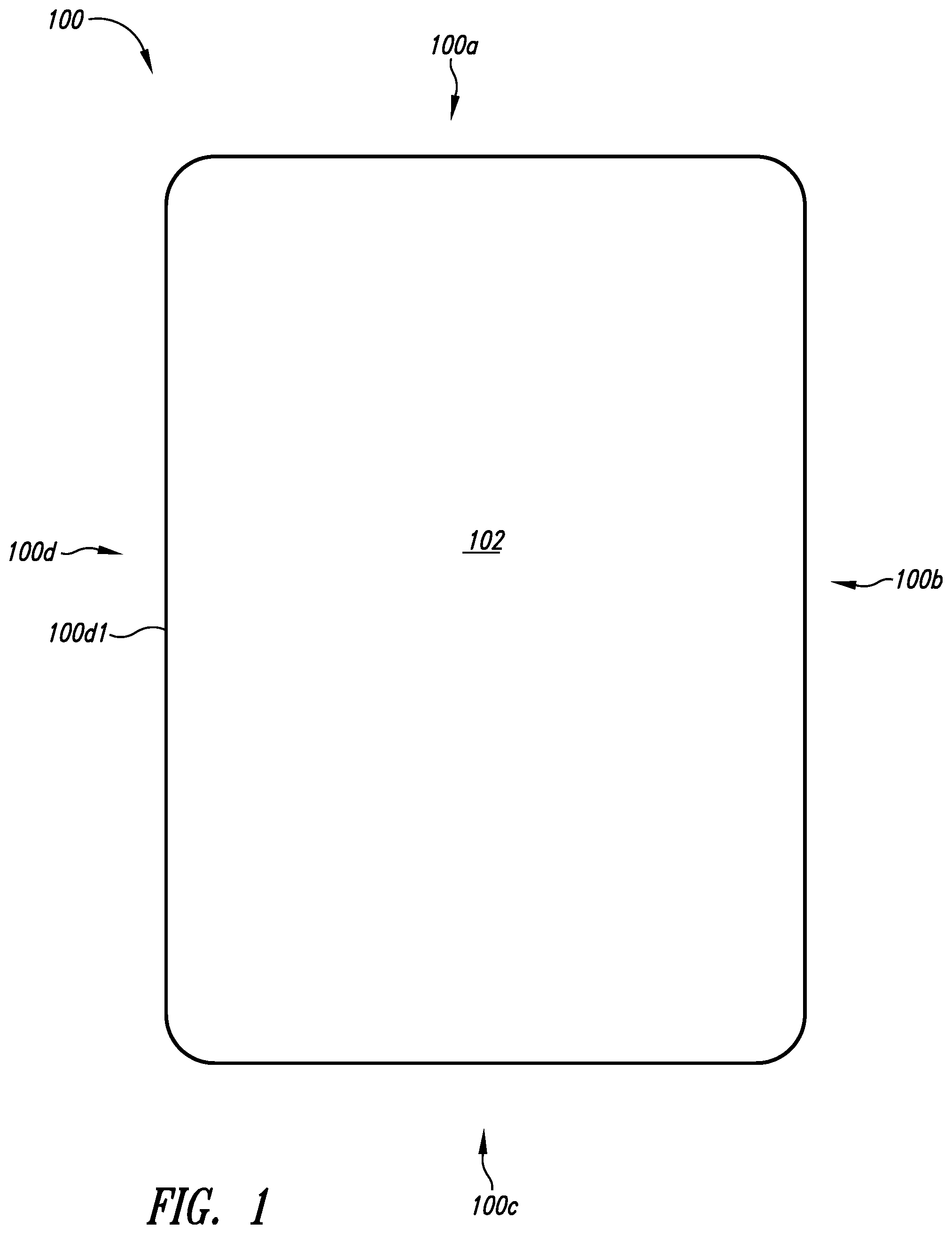
Turning to , depicted therein is a top-plan view of portable electronic device 100 . In implementations, portable electronic device 100 is shown to include side 100 a , side 100 b , side 100 c , side 100 d with portable electronic device stylus connector 100 d 1 , and display surface 102 . Implementations can include portable electronic device 100 being a tablet, laptop, mobile phone, etc.
Turning to , depicted therein is a side-elevational view of portable electronic device 100 showing detail of portable electronic device stylus connector 100 d 1 , which in implementations can include one or more magnetic materials for stylus coupling further discussed herein.
Turning to , depicted therein is a bottom-plan view of portable electronic device stylus 120 including flattened surface 120 a , end 120 b , curvilinear surface 120 c , and pointed tip 120 d . In implementations, one or more magnetic materials can be positioned on or beneath flattened surface 120 a to allow for coupling of portable electronic device stylus 120 with portable electronic device stylus connector 100 d 1 of portable electronic device 100 .
Turning to , depicted therein is a cross-sectional view of portable electronic device stylus 120 of taken along the 4 - 4 cut line of .
Turning to , depicted therein is a top-plan view of portable electronic device stylus 120 , which is shown to include linear dimension P 1 , linear dimension P 2 , linear dimension P 3 , and linear dimension P 4 . In implementations linear dimension P 1 can be 5 to 7 inches, such as 6.53 inches, and linear dimension P 4 can be 0.3 to 0.5 inches, such as 0.35 inches. In other implementations other dimensions of other versions of portable electronic device stylus 120 can be used.
Turning to , depicted therein is a top-plan view of portable electronic device 100 and portable electronic device stylus 120 as uncoupled from portable electronic device 100 .
Turning to is a top-plan view of portable electronic device 100 and portable electronic device stylus 120 as coupled with portable electronic device 100 .
Turning to , depicted therein is a top-plan view of device case assembly 10 for portable electronic device 100 . The device case assembly 10 is shown to include interior base surface 12 , and exterior 14 . The interior base surface 12 is shown to include interior wall portion 12 a , interior wall portion 12 b , interior wall portion 12 c , and interior wall portion 12 d . The exterior 14 is shown to include exterior wall portion 14 a , exterior wall portion 14 b , exterior wall portion 14 c and exterior wall portion 14 d . Implementations of one or more portions of device case assembly 10 can include at least one of the following materials: rigid plastic, polycarbonate, acrylonitrile butadiene styrene, thermoplastic polymer, thermoplastic polyurethane, polyethylene terephthalate, and nylon.
Turning to , depicted therein is a front-perspective view of device case assembly 10 shown to include linear dimension L 1 and linear dimension L 2 . The exterior wall portion 14 b is shown to include corner 14 b 1 , recess end 14 b 2 , edge portion 14 b 3 , edge portion 14 b 4 , recess end 14 b 5 , and corner 14 b 6 . The portable electronic device stylus holder 16 is shown to include elongated aperture 16 a , tip recess portion 16 b , end recess portion 16 c , beveled surface portion 16 d , which is shown to include tab-receiving notch 16 e 2 and tab-receiving notch 16 e 3 .
Turning to , depicted therein is a cross-sectional view of device case assembly 10 taking along the 10 - 10 cut line of shown to further include exterior base surface portion 18 .
Turning to , depicted therein is an enlarged view of a portion of device case assembly 10 taken along the dashed circle labeled 11 - 11 of shown to further include beveled surface portion 16 f.
Turning to , depicted therein is a rear-perspective view of device case assembly 10 further including tab-receiving notch 16 e 1 and tab-receiving notch 16 g.
Turning to , depicted therein is a side-elevational view of device case assembly 10 .
Turning to , depicted therein is a cross-sectional view of device case assembly 10 taken along the 14 - 14 cut line of .
Turning to , depicted therein is an enlarged view of a portion of device case assembly 10 taken along the dashed circle labeled “15” of with tab-receiving notch 16 e 1 shown to include notch portion 16 e 1 a and notch portion 16 e 1 b , notch portion 16 e 1 c , and notch portion 16 e 1 d.
Turning to , depicted therein is a side-elevational view of device case assembly 10 and portable electronic device 100 .
Turning to , depicted therein is a cross-sectional view of device case assembly 10 and portable electronic device 100 taken along the 17 - 17 cut line of .
Turning to , depicted therein is an enlarged view of device case assembly 10 and portable electronic device 100 taken along the dashed circle labeled “18” of .
Turning to , depicted therein is a front-perspective view of device case assembly 10 and portable electronic device stylus 120 .
Turning to , depicted therein is a cross-sectional view of device case assembly 10 and portable electronic device stylus 120 taken along the 20 - 20 cut line of .
Turning to , depicted therein is an enlarged view of device case assembly 10 and portable electronic device stylus 120 taken along the dashed circle labeled “21” of .
Turning to , depicted therein is a side-elevational view of device case assembly 10 and portable electronic device stylus 120 .
Turning to , depicted therein is a top-plan view of cover assembly 30 including curvilinear surface 30 a , end 30 b , pointed tip 30 c , tab 30 d 1 , tab 30 d 2 , side 30 e 1 , and side 30 e 2 . The cover assembly 30 is shown to further include linear dimension C 1 , linear dimension C 2 , linear dimension C 3 , and linear dimension C 4 . Implementations of one or more portions of cover assembly 30 can include at least one of the following materials: rigid plastic, polycarbonate, acrylonitrile butadiene styrene, thermoplastic polymer, thermoplastic polyurethane, polyethylene terephthalate, and nylon.
Turning to , depicted therein is a rear-perspective view of cover assembly 30 shown to further include support 30 f , and void 30 g.
Turning to , depicted therein is a bottom-plan view of cover assembly 30 .
Turning to , depicted therein is a cross-sectional view of the cover assembly of taken along the 26 - 26 cut line of with tab 30 d 1 shown to include tab portion 30 d 1 a , tab portion 30 d 1 b , tab portion 30 d 1 c , tab portion 30 d 1 d , and tab portion 30 d 1 e.
Turning to , depicted therein is a cross-sectional view of the cover assembly of taken along the 27 - 27 cut line of with tab 30 d 1 shown to include tab portion 30 d 2 a , tab portion 30 d 2 b , tab portion 30 d 2 c , tab portion 30 d 2 d , and tab portion 30 d 2 e.
Turning to , depicted therein is a cross-sectional view of the cover assembly of taken along the 28 - 28 cut line of with tab 30 d 1 shown to include tab portion 30 d 3 a , tab portion 30 d 3 b , tab portion 30 d 3 c , tab portion 30 d 3 d , tab portion 30 d 3 e , tab portion 30 d 3 f , and tab portion 30 d 3 g.
Turning to , depicted therein is a side-elevational view of cover assembly 30 .
Turning to , depicted therein is a side-elevational view of cover assembly 30 .
Turning to , depicted therein is a side-elevational view of device case assembly 10 and cover assembly 30 .
Turning to , depicted therein is a cross-sectional of device case assembly 10 and cover assembly 30 taken along the 32 - 32 cut line of .
Turning to , depicted therein is an enlarged view of the device case assembly of and the cover assembly of taken along the dashed circle labeled “33” of .
Turning to , depicted therein is a cross-sectional of the device case assembly of and the cover assembly of taken along the 34 - 34 cut line of .
Turning to , depicted therein is an enlarged view of the device case assembly of and the cover assembly of taken along the dashed circle labeled “35” of with tab-receiving notch 16 e 2 shown to include notch portion 16 e 2 a , notch portion 16 e 2 b , and notch portion 16 e 2 c.
Turning to , depicted therein is a cross-sectional of the device case assembly of and the cover assembly of taken along the 36 - 36 cut line of .
Turning to , depicted therein is an enlarged view of the device case assembly of and the cover assembly of taken along the dashed circle labeled “37” of with tab-receiving notch 16 e 3 shown to include notch portion 16 e 3 a , notch portion 16 e 3 b , notch portion 16 e 3 c , notch portion 16 e 3 d , notch portion 16 e 3 e , and notch portion 16 e 3 f.
While particular aspects of the present subject matter described herein have been shown and described, it will be apparent to those skilled in the art that, based upon the teachings herein, changes and modifications may be made without departing from the subject matter described herein and its broader aspects and, therefore, the appended claims are to encompass within their scope all such changes and modifications as are within the true spirit and scope of the subject matter described herein. It will be understood by those within the art that, in general, terms used herein, and especially in the appended claims (e.g., bodies of the appended claims) are generally intended as “open” terms (e.g., the term “including” should be interpreted as “including but not limited to,” the term “having” should be interpreted as “having at least,” the term “includes” should be interpreted as “includes but is not limited to,” etc.). It will be further understood by those within the art that if a specific number of an introduced claim recitation is intended, such an intent will be explicitly recited in the claim, and in the absence of such recitation no such intent is present. For example, as an aid to understanding, the following appended claims may contain usage of the introductory phrases “at least one” and “one or more” to introduce claim recitations. However, the use of such phrases should not be construed to imply that the introduction of a claim recitation by the indefinite articles “a” or “an” limits any particular claim containing such introduced claim recitation to claims containing only one such recitation, even when the same claim includes the introductory phrases “one or more” or “at least one” and indefinite articles such as “a” or “an” (e.g., “a” and/or “an” should typically be interpreted to mean “at least one” or “one or more”); the same holds true for the use of definite articles used to introduce claim recitations. In addition, even if a specific number of an introduced claim recitation is explicitly recited, those skilled in the art will recognize that such recitation should typically be interpreted to mean at least the recited number (e.g., the bare recitation of “two recitations,” without other modifiers, typically means at least two recitations, or two or more recitations). Furthermore, in those instances where a convention analogous to “at least one of A, B, and C, etc.” is used, in general such a construction is intended in the sense one having skill in the art would understand the convention (e.g., “a system having at least one of A, B, and C” would include but not be limited to systems that have A alone, B alone, C alone, A and B together, A and C together, B and C together, and/or A, B, and C together, etc.). In those instances where a convention analogous to “at least one of A, B, or C, etc.” is used, in general such a construction is intended in the sense one having skill in the art would understand the convention (e.g., “a system having at least one of A, B, or C” would include but not be limited to systems that have A alone, B alone, C alone, A and B together, A and C together, B and C together, and/or A, B, and C together, etc.). It will be further understood by those within the art that typically a disjunctive word and/or phrase presenting two or more alternative terms, whether in the description, claims, or drawings, should be understood to contemplate the possibilities of including one of the terms, either of the terms, or both terms unless context dictates otherwise. For example, the phrase “A or B” will be typically understood to include the possibilities of “A” or “B” or “A and B.”
With respect to the appended claims, those skilled in the art will appreciate that recited operations therein may generally be performed in any order. Also, although various operational flows are presented in a sequence(s), it should be understood that the various operations may be performed in other orders than those which are illustrated, or may be performed concurrently. Examples of such alternate orderings may include overlapping, interleaved, interrupted, reordered, incremental, preparatory, supplemental, simultaneous, reverse, or other variant orderings, unless context dictates otherwise. Furthermore, terms like “responsive to,” “related to,” or other past-tense adjectives are generally not intended to exclude such variants, unless context dictates otherwise.
Figures (20)
Citations
This patent cites (21)
- US2461711
- US6445577
- US6473076
- US6646864
- US7495895
- US9144279
- US10135480
- US10411748
- US11068023
- US20030076302
- US20040109285
- US20040112143
- US20040145579
- US20060044288
- US20120261306
- US20140020947
- US20140138265
- US20150055285
- US20150298859
- US20170108952
- US20230144918