Abstract
A wide-angle lens assembly includes a first, second, third, fourth, fifth, sixth, seventh, eighth, and ninth lenses. The first and second lenses are with negative refractive power and include a convex surface facing an object side and a concave surface facing an image side respectively. The third lens is a biconcave lens with negative refractive power. The fourth and fifth lenses are biconvex lenses with positive refractive power. The sixth lens is with positive refractive power and includes a convex surface facing the image side. The seventh lens is with negative refractive power and includes a concave surface facing the object side. The eighth lens is with positive refractive power and includes a convex surface facing the object side. The ninth lens is with positive refractive power and includes a concave surface facing the object side and a convex surface facing the image side.
Claims (17)
1. A wide-angle lens assembly comprising: a first lens which is with negative refractive power and comprises a convex surface facing an object side and a concave surface facing an image side; a second lens which is with negative refractive power and comprises a convex surface facing the object side and a concave surface facing the image side; a third lens which is with negative refractive power and comprises a concave surface facing the object side and another concave surface facing the image side; a fourth lens which is with positive refractive power and comprises a convex surface facing the object side and another convex surface facing the image side; a fifth lens which is with positive refractive power and comprises a convex surface facing the object side and another convex surface facing the image side; a sixth lens which is with positive refractive power and comprises a convex surface facing the image side; a seventh lens which is with negative refractive power and comprises a concave surface facing the object side; an eighth lens which is with positive refractive power and comprises a convex surface facing the object side; and a ninth lens which is with positive refractive power and comprises a concave surface facing the object side and a convex surface facing the image side; wherein the wide-angle lens assembly satisfies the following condition: 3.3 mm< BFL <4 mm; wherein BFL is an interval from an image side surface of the ninth lens to an image plane along the optical axis; wherein the first lens, the second lens, the third lens, the fourth lens, the fifth lens, the sixth lens, the seventh lens, the eighth lens, and the ninth lens are arranged in order from the object side to the image side along an optical axis.
10. A wide-angle lens assembly comprising: a first lens which is with negative refractive power and comprises a convex surface facing an object side and a concave surface facing an image side; a second lens which is with negative refractive power and comprises a convex surface facing the object side and a concave surface facing the image side; a third lens which is with negative refractive power and comprises a concave surface facing the object side and another concave surface facing the image side; a fourth lens which is with positive refractive power and comprises a convex surface facing the object side and another convex surface facing the image side; a fifth lens which is with positive refractive power and comprises a convex surface facing the object side and another convex surface facing the image side; a stop; a sixth lens which is with positive refractive power and comprises a convex surface facing the image side; a seventh lens which is with negative refractive power and comprises a concave surface facing the object side; an eighth lens which is with positive refractive power and comprises a convex surface facing the object side; and a ninth lens which is with positive refractive power and comprises a concave surface facing the object side and a convex surface facing the image side; wherein the wide-angle lens assembly satisfies the following condition: 3.3 mm< BFL <4 mm; wherein BFL is an interval from an image side surface of the ninth lens to an image plane along the optical axis; wherein the first lens, the second lens, the third lens, the fourth lens, the fifth lens, the stop, the sixth lens, the seventh lens, the eighth lens, and the ninth lens are arranged in order from the object side to the image side along an optical axis.
Show 15 dependent claims
2. The wide-angle lens assembly as claimed in claim 1 , further comprising a stop disposed between the fifth lens and the sixth lens, wherein the sixth lens is cemented with the seventh lens.
3. The wide-angle lens assembly as claimed in claim 1 , wherein: the sixth lens further comprises another convex surface facing the object side; the seventh lens further comprises another concave surface facing the image side; and the eighth lens further comprises another convex surface facing the image side.
4. The wide-angle lens assembly as claimed in claim 1 , wherein the wide-angle lens assembly satisfies the following condition: | DT |≤5%; wherein DT is a F-theta distortion of the wide-angle lens assembly.
5. The wide-angle lens assembly as claimed in claim 1 , wherein the wide-angle lens assembly satisfies the following condition: | P V-IR |≤8 μm; wherein P V-IR is an interval from a clearest image plane of a visible light to a clearest image plane of a infrared light along the optical axis.
6. The wide-angle lens assembly as claimed in claim 1 , wherein the wide-angle lens assembly satisfies the following condition: −0.7 mm −1 ≤1/( Nd 1 ×f 1 )+1/( Nd 2 ×f 2 )+1/( Nd 3 ×f 3 )+1/( Nd 4 ×f 4 )+1/( Nd 5 ×f 5 )+1/( Nd 6 ×f 6 )+1/( Nd 7 ×f 7 )+1/( Nd 8 ×f 8 )+1/( Nd 9 ×f 9 )≤0.7 mm −1 ; wherein Nd 1 is an index of refraction of the first lens, Nd 2 is an index of refraction of the second lens, Nd 3 is an index of refraction of the third lens, Nd 4 is an index of refraction of the fourth lens, Nd 3 is an index of refraction of the fifth lens, Nd 6 is an index of refraction of the sixth lens, Nd 7 is an index of refraction of the seventh lens, Nd 8 is an index of refraction of the eighth lens, Nd 9 is an index of refraction of the ninth lens, f 1 is an effective focal length of the first lens, f 2 is an effective focal length of the second lens, f 3 is an effective focal length of the third lens, f 4 is an effective focal length of the fourth lens, f 5 is an effective focal length of the fifth lens, f 6 is an effective focal length of the sixth lens, f 7 is an effective focal length of the seventh lens, f 8 is an effective focal length of the eighth lens, and f 9 is an effective focal length of the ninth lens.
7. The wide-angle lens assembly as claimed in claim 1 , wherein the wide-angle lens assembly satisfies the following condition: 1.5 <TTL/D 1 <2; wherein TTL is an interval from an object side surface of the first lens to an image plane along the optical axis and D 1 is an effective optical diameter of the first lens.
8. The wide-angle lens assembly as claimed in claim 1 , wherein the wide-angle lens assembly satisfies the following condition: 50 ≤Vd 6 −Vd 7 ≤70; wherein Vd 6 is an Abbe number of the sixth lens and Vd 7 is an Abbe number of the seventh lens.
9. The wide-angle lens assembly as claimed in claim 1 , wherein the wide-angle lens assembly satisfies the following condition: 135 degrees/mm<FOV/ f <170 degrees/mm; wherein FOV is a full field of view of the wide-angle lens assembly and f is an effective focal length of the wide-angle lens assembly.
11. The wide-angle lens assembly as claimed in claim 10 , wherein: the sixth lens further comprises another convex surface facing the object side; the seventh lens further comprises another concave surface facing the image side; the eighth lens further comprises another convex surface facing the image side; and the sixth lens is cemented with the seventh lens.
12. The wide-angle lens assembly as claimed in claim 10 , wherein the wide-angle lens assembly satisfies the following condition: | DT |≤5%; wherein DT is a F-theta distortion of the wide-angle lens assembly.
13. The wide-angle lens assembly as claimed in claim 10 , wherein the wide-angle lens assembly satisfies the following condition: | P V-IR |≤8 μm; wherein P V-IR is an interval from a clearest image plane of a visible light to a clearest image plane of a infrared light along the optical axis.
14. The wide-angle lens assembly as claimed in claim 10 , wherein the wide-angle lens assembly satisfies the following condition: −0.7 mm −1 ≤1/( Nd 1 ×f 1 )+1/( Nd 2 ×f 2 )+1/( Nd 3 ×f 3 )+1/( Nd 4 ×f 4 )+1/( Nd 5 ×f 5 )+1/( Nd 6 ×f 6 )+1/( Nd 7 ×f 7 )+1/( Nd 8 ×f 8 )+1/( Nd 9 ×f 9 )≤0.7 mm −1 ; wherein Nd 1 is an index of refraction of the first lens, Nd 2 is an index of refraction of the second lens, Nd 3 is an index of refraction of the third lens, Nd 4 is an index of refraction of the fourth lens, Nd 5 is an index of refraction of the fifth lens, Nd 6 is an index of refraction of the sixth lens, Nd 7 is an index of refraction of the seventh lens, Nd 8 is an index of refraction of the eighth lens, Nd 9 is an index of refraction of the ninth lens, f 1 is an effective focal length of the first lens, f 2 is an effective focal length of the second lens, f 3 is an effective focal length of the third lens, f 4 is an effective focal length of the fourth lens, f 5 is an effective focal length of the fifth lens, f 6 is an effective focal length of the sixth lens, f 7 is an effective focal length of the seventh lens, f 8 is an effective focal length of the eighth lens, and f 9 is an effective focal length of the ninth lens.
15. The wide-angle lens assembly as claimed in claim 10 , wherein the wide-angle lens assembly satisfies the following conditions: 1.5 <TTL/D 1 <2; wherein TTL is an interval from an object side surface of the first lens to the image plane along the optical axis, and D 1 is an effective optical diameter of the first lens.
16. The wide-angle lens assembly as claimed in claim 10 , wherein the wide-angle lens assembly satisfies the following condition: 50 ≤Vd 6 −Vd 7 ≤70; wherein Vd 6 is an Abbe number of the sixth lens and Vd 7 is an Abbe number of the seventh lens.
17. The wide-angle lens assembly as claimed in claim 10 , wherein the wide-angle lens assembly satisfies the following condition: 135 degrees/mm<FOV/ f <170 degrees/mm; wherein FOV is a full field of view of the wide-angle lens assembly and f is an effective focal length of the wide-angle lens assembly.
Full Description
Show full text →
BACKGROUND OF THE INVENTION
Field of the Invention
The invention relates to a wide-angle lens assembly.
Description of the Related Art
The field of view of today's wide-angle lens assembly is getting larger and larger. Although it is able to capture very wide image, but there will be a phenomenon that the closer to the periphery, the smaller the image. Furthermore, with different application requirement, it is necessary to capture visible light image during the day and infrared light image at night. However, the known wide-angle lens assembly cannot maintain the image quality of visible light and infrared light with good optical performance simultaneously. Therefore, the wide-angle lens assembly needs a new structure in order to meet the above requirement at the same time.
BRIEF SUMMARY OF THE INVENTION
The invention provides a wide-angle lens assembly to solve the above problems. The wide-angle lens assembly of the invention is provided with characteristics of an increased field of view, an increased periphery image, a maintained image quality of visible light and infrared light with good optical performance simultaneously, a resisted environmental temperature change, and still has a good optical performance.
The wide-angle lens assembly in accordance with an exemplary embodiment of the invention includes a first, second, third, fourth, fifth, sixth, seventh, eighth, and ninth lenses, all of which are arranged in order from an object side to an image side along an optical axis. The first and second lenses are with negative refractive power and include a convex surface facing the object side and a concave surface facing the image side respectively. The third lens is a biconcave lens with negative refractive power. The fourth and fifth lenses are biconvex lenses with positive refractive power. The sixth lens is with positive refractive power and includes a convex surface facing the image side. The seventh lens is with negative refractive power and includes a concave surface facing the object side. The eighth lens is with positive refractive power and includes a convex surface facing the object side. The ninth lens is with positive refractive power and includes a concave surface facing the object side and a convex surface facing the image side.
In another exemplary embodiment, the wide-angle lens assembly further includes a stop disposed between the fifth lens and the sixth lens, wherein the sixth lens is cemented with the seventh lens.
In yet another exemplary embodiment, the sixth lens further includes another convex surface facing the object side, the seventh lens further includes another concave surface facing the image side, and the eighth lens further includes another convex surface facing the image side.
In another exemplary embodiment, the wide-angle lens assembly satisfies the following condition: |DT|≤5%; wherein DT is a F-theta distortion of the wide-angle lens assembly.
In yet another exemplary embodiment, the wide-angle lens assembly satisfies the following condition: |P V-IR |≤8 μm; wherein P V-IR is an interval from a clearest image plane of a visible light to a clearest image plane of a infrared light along the optical axis.
In another exemplary embodiment, the wide-angle lens assembly satisfies the following condition: 3.3 mm<BFL<4 mm; wherein BFL is an interval from an image side surface of the ninth lens to an image plane along the optical axis.
In yet another exemplary embodiment, the wide-angle lens assembly satisfies the following condition: −0.7 mm −1 ≤1/(Nd 1 ×f 1 )+1/(Nd 2 ×f 2 )+1/(Nd 3 ×f 3 )+1/(Nd 4 ×f 4 )+1/(Nd 5 ×f 5 )+1/(Nd 6 ×f 6 )+1/(Nd 7 ×f 7 )+1/(Nd 8 ×f 8 )+1/(Nd 9 ×f 9 )≤0.7 mm −1 ; wherein Nd 1 is an index of refraction of the first lens, Nd 2 is an index of refraction of the second lens, Nd 3 is an index of refraction of the third lens, Nd 4 is an index of refraction of the fourth lens, Nd 5 is an index of refraction of the fifth lens, Nd 6 is an index of refraction of the sixth lens, Nd 7 is an index of refraction of the seventh lens, Nd 8 is an index of refraction of the eighth lens, Nd 9 is an index of refraction of the ninth lens, f 1 is an effective focal length of the first lens, f 2 is an effective focal length of the second lens, f 3 is an effective focal length of the third lens, f 4 is an effective focal length of the fourth lens, f 5 is an effective focal length of the fifth lens, f 6 is an effective focal length of the sixth lens, f 7 is an effective focal length of the seventh lens, f 8 is an effective focal length of the eighth lens, and f 9 is an effective focal length of the ninth lens.
In another exemplary embodiment, the wide-angle lens assembly satisfies the following condition: 1.5<TTL/D 1 <2; wherein TTL is an interval from an object side surface of the first lens to an image plane along the optical axis and D 1 is an effective optical diameter of the first lens.
In yet another exemplary embodiment, the wide-angle lens assembly satisfies the following condition: 50≤Vd 6 −Vd 7 ≤70; wherein Vd 6 is an Abbe number of the sixth lens and Vd 7 is an Abbe number of the seventh lens.
In another exemplary embodiment, the wide-angle lens assembly satisfies the following condition: 135 degrees/mm<FOV/f<170 degrees/mm; wherein FOV is a full field of view of the wide-angle lens assembly and f is an effective focal length of the wide-angle lens assembly.
In yet another exemplary embodiment, the wide-angle lens assembly further includes a reflective element disposed between the second lens and the third lens.
The wide-angle lens assembly in accordance with another exemplary embodiment of the invention includes a first lens, a second lens, a third lens, a fourth lens, a fifth lens, a stop, a sixth lens, a seventh lens, an eighth lens, and a ninth lens, all of which are arranged in order from an object side to an image side along an optical axis. The first and second lenses are with negative refractive power and include a convex surface facing the object side and a concave surface facing the image side respectively. The third lens is a biconcave lens with negative refractive power. The fourth and fifth lenses are biconvex lenses with positive refractive power. The sixth lens is with positive refractive power and includes a convex surface facing the image side. The seventh lens is with negative refractive power and includes a concave surface facing the object side. The eighth lens is with positive refractive power and includes a convex surface facing the object side. The ninth lens is with positive refractive power and includes a concave surface facing the object side and a convex surface facing the image side.
A detailed description is given in the following embodiments with reference to the accompanying drawings.
BRIEF DESCRIPTION OF THE DRAWINGS
The invention can be more fully understood by reading the subsequent detailed description and examples with references made to the accompanying drawings, wherein:
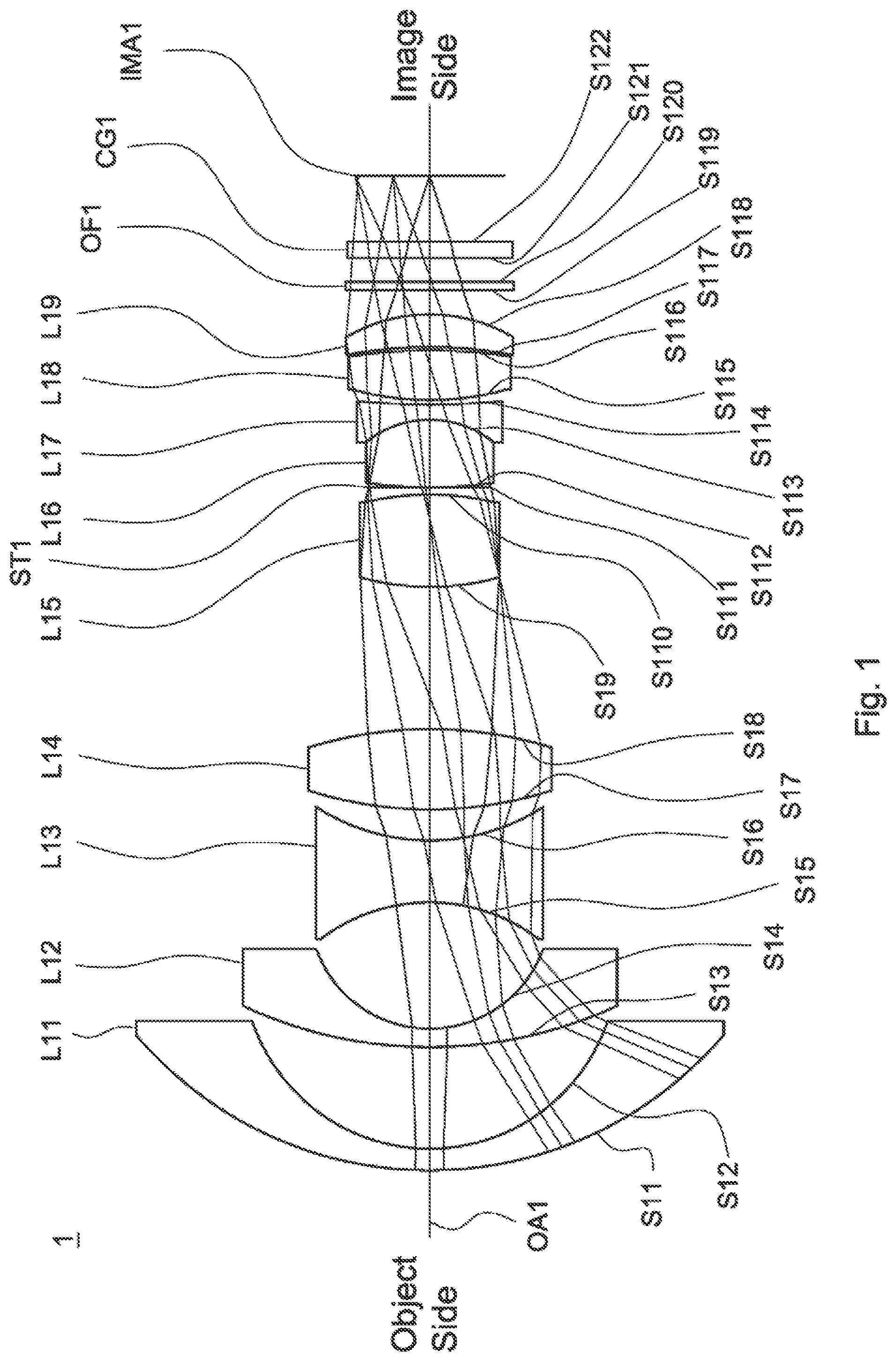
is a lens layout and optical path diagram of a wide-angle lens assembly in accordance with a first embodiment of the invention;
A depicts a longitudinal aberration diagram of the wide-angle lens assembly in accordance with the first embodiment of the invention;
B is a field curvature diagram of the wide-angle lens assembly in accordance with the first embodiment of the invention;
C is a F-theta distortion diagram of the wide-angle lens assembly in accordance with the first embodiment of the invention;
is a lens layout and optical path diagram of a wide-angle lens assembly in accordance with a second embodiment of the invention;
A depicts a longitudinal aberration diagram of the wide-angle lens assembly in accordance with the second embodiment of the invention;
B is a field curvature diagram of the wide-angle lens assembly in accordance with the second embodiment of the invention;
C is a F-theta distortion diagram of the wide-angle lens assembly in accordance with the first embodiment of the invention;
is a lens layout and optical path diagram of a wide-angle lens assembly in accordance with a third embodiment of the invention;
A depicts a longitudinal aberration diagram of the wide-angle lens assembly in accordance with the third embodiment of the invention;
B is a field curvature diagram of the wide-angle lens assembly in accordance with the third embodiment of the invention; and
C is a F-theta distortion diagram of the wide-angle lens assembly in accordance with the third embodiment of the invention.
DETAILED DESCRIPTION OF THE INVENTION
The following description is made for the purpose of illustrating the general principles of the invention and should not be taken in a limiting sense. The scope of the invention is best determined by reference to the appended claims.
The present invention provides a wide-angle lens assembly including a first lens, a second lens, a third lens, a fourth lens, a fifth lens, a sixth lens, a seventh lens, an eighth lens, and a ninth lens. The first lens which is with negative refractive power and includes a convex surface facing an object side and a concave surface facing an image side. The second lens which is with negative refractive power and includes a convex surface facing the object side and a concave surface facing the image side. The third lens which is with negative refractive power and includes a concave surface facing the object side and another concave surface facing the image side. The fourth lens which is with positive refractive power and includes a convex surface facing the object side and another convex surface facing the image side. The fifth lens which is with positive refractive power and includes a convex surface facing the object side and another convex surface facing the image side. The sixth lens which is with positive refractive power and includes a convex surface facing the image side. The seventh lens which is with negative refractive power and includes a concave surface facing the object side. The eighth lens which is with positive refractive power and includes a convex surface facing the object side. The ninth lens which is with positive refractive power and includes a concave surface facing the object side and a convex surface facing the image side. The first lens, the second lens, the third lens, the fourth lens, the fifth lens, the sixth lens, the seventh lens, the eighth lens, and the ninth lens are arranged in order from the object side to the image side along an optical axis.
The present invention provides another wide-angle lens assembly including a first lens, a second lens, a third lens, a fourth lens, a fifth lens, a stop, a sixth lens, a seventh lens, an eighth lens, and a ninth lens. The first lens which is with negative refractive power and includes a convex surface facing an object side and a concave surface facing an image side. The second lens which is with negative refractive power and includes a convex surface facing the object side and a concave surface facing the image side. The third lens which is with negative refractive power and includes a concave surface facing the object side and another concave surface facing the image side. The fourth lens which is with positive refractive power and includes a convex surface facing the object side and another convex surface facing the image side. The fifth lens which is with positive refractive power and includes a convex surface facing the object side and another convex surface facing the image side. The sixth lens which is with positive refractive power and includes a convex surface facing the image side. The seventh lens which is with negative refractive power and includes a concave surface facing the object side. The eighth lens which is with positive refractive power and includes a convex surface facing the object side. The ninth lens which is with positive refractive power and includes a concave surface facing the object side and a convex surface facing the image side. The first lens, the second lens, the third lens, the fourth lens, the fifth lens, the stop, the sixth lens, the seventh lens, the eighth lens, and the ninth lens are arranged in order from the object side to the image side along an optical axis.
Referring to Table 1, Table 2, Table 4, Table 5, Table 7, and Table 8, wherein Table 1, Table 4, and Table 7 show optical specification in accordance with a first, second, and third embodiments of the invention respectively and Table 2, Table 5, and Table 8 show aspheric coefficient of each aspheric lens in Table 1, Table 4, and Table 7 respectively.
, , and are lens layout and optical path diagrams of the wide-angle lens assemblies in accordance with the first, second, and third embodiments of the invention respectively.
The first lenses L 11 , L 21 , L 31 are meniscus lenses with negative refractive power and made of glass material, wherein the object side surfaces S 11 , S 21 , S 31 are convex surfaces, the image side surfaces S 12 , S 22 , S 32 are concave surfaces, and the object side surfaces S 11 , S 21 , S 31 and the image side surfaces S 12 , S 22 , S 32 are spherical surfaces.
The second lenses L 12 , L 22 , L 32 are meniscus lenses with negative refractive power and made of glass material, wherein the object side surfaces S 13 , S 23 , S 33 are convex surfaces, the image side surfaces S 14 , S 24 , S 34 are concave surfaces, and the object side surfaces S 13 , S 23 , S 33 and the image side surfaces S 14 , S 24 , S 34 are spherical surfaces.
The third lenses L 13 , L 23 , L 33 are biconcave lenses with negative refractive power and made of glass material, wherein the object side surfaces S 15 , S 25 , S 35 are concave surfaces, the image side surfaces are S 16 , S 26 , S 36 are concave surfaces, and the object side surfaces S 15 , S 25 , S 35 and the image side surfaces S 16 , S 26 , S 36 are spherical surfaces.
The fourth lenses L 14 , L 24 , L 34 are biconvex lenses with positive refractive power and made of glass material, wherein the object side surfaces S 17 , S 27 , S 37 are convex surfaces, the image side surfaces S 18 , S 28 , S 38 are convex surfaces, and the object side surfaces S 17 , S 27 , S 37 and the image side surfaces S 18 , S 28 , S 38 are spherical surfaces.
The fifth lenses L 15 , L 25 , L 35 are biconvex lenses with positive refractive power and made of glass material, wherein the object side surfaces S 19 , S 29 , S 39 are convex surfaces, the image side surfaces S 110 , S 210 , S 310 are convex surfaces, and the object side surfaces S 19 , S 29 , S 39 and the image side surfaces S 110 , S 210 , S 310 are spherical surfaces.
The sixth lenses L 16 , L 26 , L 36 are biconvex lenses with positive refractive power and made of glass material, wherein the object side surfaces S 112 , S 212 , S 312 are convex surfaces, the image side surfaces S 113 , S 213 , S 313 are convex surfaces, and the object side surfaces S 112 , S 212 , S 312 and the image side surfaces S 113 , S 213 , S 313 are spherical surfaces.
The seventh lenses L 17 , L 27 , L 37 are biconcave lenses with negative refractive power and made of glass material, wherein the object side surfaces S 113 , S 213 , S 313 are concave surfaces, the image side surfaces S 114 , S 214 , S 314 are concave surfaces, and the object side surfaces S 113 , S 213 , S 313 and the image side surfaces S 114 , S 214 , S 314 are spherical surfaces.
The eighth lenses L 18 , L 28 , L 38 are biconvex lenses with positive refractive power and made of glass material, wherein the object side surfaces S 115 , S 215 , S 315 are convex surfaces, the image side surfaces S 116 , S 216 , S 316 are convex surfaces, and the object side surfaces S 115 , S 215 , S 315 and the image side surfaces S 116 , S 216 , S 316 are spherical surfaces.
The ninth lenses L 19 , L 29 , L 39 are meniscus lenses with positive refractive power and made of plastic material, wherein the object side surfaces S 117 , S 217 , S 317 are concave surfaces, the image side surfaces S 118 , S 218 , S 318 are convex surfaces, and the object side surfaces S 117 , S 217 , S 317 and the image side surfaces S 118 , S 218 , S 318 are aspheric surfaces.
The sixth lenses L 16 , L 26 , L 36 and the seventh lenses L 17 , L 27 , L 37 are cemented respectively.
In addition, the wide-angle lens assemblies 1 , 2 , 3 satisfy at least one of the following conditions: | DT|≤ 5%; (1) | P V-IR |≤8 μm; (2) 3.3 mm< BFL< 4 mm; (3) −0.7 mm −1 ≤1/( Nd 1 ×f 1 )+1/( Nd 2 ×f 2 )+1/( Nd 3 ×f 3 )+1/( Nd 4 ×f 4 )+1/( Nd 5 ×f 5 )+1/( Nd 6 ×f 6 )+1/( Nd 7 ×f 7 )+1/( Nd 8 ×f 8 )+1/( Nd 9 ×f 9 )≤0.7 mm −1 ; (4) 1.5< TTL/D 1 <2; (5) 50≤ Vd 6 −Vd 7 ≤70; (6) 135 degrees/mm<FOV/ f< 170 degrees/mm; (7)
wherein DT is a F-theta distortion of the wide-angle lens assemblies 1 , 2 , 3 for the first to third embodiments, P V-IR is an interval from a clearest image plane of a visible light to a clearest image plane of a infrared light along the optical axes OA 1 , OA 2 , OA 3 for the first to third embodiments, BFL is an interval from image side surfaces S 118 , S 218 , S 318 of the ninth lenses L 19 , L 29 , L 39 to image planes IMA 1 , IMA 2 , IMA 3 along the optical axes OA 1 , OA 2 , OA 3 respectively for the first to third embodiments, Nd 1 is an index of refraction of the first lenses L 11 , L 21 , L 31 for the first to third embodiments, Nd 2 is an index of refraction of the second lenses L 12 , L 22 , L 32 for the first to third embodiments, Nd 3 is an index of refraction of the third lenses L 13 , L 23 , L 33 for the first to third embodiments, Nd 4 is an index of refraction of the fourth lenses L 14 , L 24 , L 34 for the first to third embodiments, Nd 5 is an index of refraction of the fifth lenses L 15 , L 25 , L 35 for the first to third embodiments, Nd 6 is an index of refraction of the sixth lenses L 16 , L 26 , L 36 for the first to third embodiments, Nd 7 is an index of refraction of the seventh lenses L 17 , L 27 , L 37 for the first to third embodiments, Nd 8 is an index of refraction of the eighth lenses L 18 , L 28 , L 38 for the first to third embodiments, Nd 9 is an index of refraction of the ninth lenses L 19 , L 29 , L 39 for the first to third embodiments, f 1 is an effective focal length of the first lenses L 11 , L 21 , L 31 for the first to third embodiments, f 2 is an effective focal length of the second lenses L 12 , L 22 , L 32 for the first to third embodiments, f 3 is an effective focal length of the third lenses L 13 , L 23 , L 33 for the first to third embodiments, f 4 is an effective focal length of the fourth lenses L 14 , L 24 , L 34 for the first to third embodiments, f 3 is an effective focal length of the fifth lenses L 15 , L 25 , L 35 for the first to third embodiments, f 6 is an effective focal length of the sixth lenses L 16 , L 26 , L 36 for the first to third embodiments, f 7 is an effective focal length of the seventh lenses L 17 , L 27 , L 37 for the first to third embodiments, f 8 is an effective focal length of the eighth lenses L 18 , L 28 , L 38 for the first to third embodiments, f 9 is an effective focal length of the ninth lenses L 19 , L 29 , L 39 for the first to third embodiments, TTL is an interval from an object side surfaces S 1 , S 21 , S 31 of the first lenses L 11 , L 21 , L 31 to image planes IMA 1 , IMA 2 , IMA 3 along the optical axes OA 1 , OA 2 , OA 3 respectively for the first to third embodiments, D 1 is an effective optical diameter of the first lenses L 11 , L 21 , L 31 for the first to third embodiments, Vd 6 is an Abbe number of the sixth lenses L 16 , L 26 , L 36 for the first to third embodiments, Vd 7 is an Abbe number of the seventh lenses L 17 , L 27 , L 37 for the first to third embodiments, FOV is a full field of view of the wide-angle lens assemblies 1 , 2 , 3 for the first to third embodiments, and f is an effective focal length of the wide-angle lens assemblies 1 , 2 , 3 for the first to third embodiments. With the lens assemblies 1 , 2 , 3 satisfying at least one of the above conditions (1)-(7), the field of view can be effectively increased, the peripheral image can be effectively increased, the back focal length can be effectively increased, the quality of infrared light image can be effectively increased, the environmental temperature change can be effectively resisted, the aberration can be effectively corrected, and the chromatic aberration can be effectively corrected.
When the condition (1): |DT|≤5% is satisfied, the peripheral image can be effectively increased.
When the condition (2): |P V-IR |≤8 μm is satisfied, the image of visible light and infrared light can be maintained with good optical performance simultaneously.
When the condition (3): 3.3 mm<BFL<4 mm is satisfied, the back focal length is longer, which is benefit to the assembly and manufacturing of the wide-angle lens assembly.
When the condition (4): −0.7 mm −1 ≤1/(Nd 1 ×f 1 )+1/(Nd 2 ×f 2 )+1/(Nd 3 ×f 3 )+1/(Nd 4 ×f 4 )+1/(Nd 5 ×f 5 )+1/(Nd 6 ×f 6 )+1/(Nd 7 ×f 7 )+1/(Nd 8 ×f 8 )+1/(Nd 9 ×f 9 )≤0.7 mm −1 is satisfied, the field of view can be corrected with the best effect.
When the condition (5): 1.5<TTL/D 1 <2 is satisfied, the total lens length is shorter.
When the condition (6): 50≤Vd 6 −Vd 7 ≤70 is satisfied, the chromatic aberration can be better corrected.
When the condition (7): 135 degrees/mm<FOV/f<170 degrees/mm is satisfied, the F-theta distortion can be controlled effectively.
When the first to eighth lenses are glass spherical lenses and the ninth lens is a plastic aspherical lens, the number of lenses can be effectively reduced and the environmental temperature change can be effectively resisted.
A detailed description of a wide-angle lens assembly in accordance with a first embodiment of the invention is as follows. Referring to , the wide-angle lens assembly 1 includes a first lens L 11 , a second lens L 12 , a third lens L 13 , a fourth lens L 14 , a fifth lens L 15 , a stop ST 1 , a sixth lens L 16 , a seventh lens L 17 , an eighth lens L 18 , a ninth lens L 19 , an optical filter OF 1 , and a cover glass CG 1 , all of which are arranged in order from an object side to an image side along an optical axis OA 1 . In operation, an image of light rays from the object side is formed at an image plane IMA 1 .
According to the foregoing, wherein: both of the object side surface S 119 and image side surface S 120 of the optical filter OF 1 are plane surfaces; and both of the object side surface S 121 and image side surface S 122 of the cover glass CG 1 are plane surfaces.
With the above design of the lenses and stop ST 1 and at least any one of the conditions (1)-(7) satisfied, the wide-angle lens assembly 1 can have an effective increased field of view, an effective increased peripheral image, an effective increased back focal length, an effective increased image quality of infrared light, an effective resisted environmental temperature change, an effective corrected aberration, and an effective corrected chromatic aberration.
Table 1 shows the optical specification of the wide-angle lens assembly 1 in .
TABLE 1
Effective Focal Length = 1.217 mm F-number = 1.64
Total Lens Length = 25.60 mm Field of View = 190 degrees
Radius of Effective
Surface Curvature Thickness Focal Length
Number (mm) (mm) Nd Vd (mm) Remark
S11 10.01 0.56 1.89 41 −11.1254 The First Lens L11
S12 4.86 2.62
S13 11.69 0.46 1.89 41 −4.8799 The Second Lens L12
S14 3.12 3.26
S15 −4.71 1.61 1.5 83 −4.81402 The Third Lens L13
S16 5.51 0.78
S17 10.08 2.07 1.96 32 5.638931 The Fourth Lens L14
S18 −10.65 3.65
S19 6.62 2.38 1.5 83 7.197634 The Fifth Lens L15
S110 −6.97 0.18
S111 ∞ 0.01 Stop ST1
S112 11.34 1.72 1.5 83 4.487844 The Sixth Lens L16
S113 −2.66 0.40 1.846 23.77 −2.7349 The Seventh Lens L17
S114 20.13 0.12
S115 7.35 1.29 1.6 68 8.0063 The Eighth Lens L18
S116 −13.04 0.09
S117 −11.95 0.83 1.64 25 8.9909 The Ninth Lens L19
S118 −4.01 0.63
S119 ∞ 0.21 1.52 64 Optical Filter OF1
S120 ∞ 1.88
S121 ∞ 0.40 1.52 64 Cover Glass CG1
S122 ∞ 0.45
The aspheric surface sag z of each aspheric lens in table 1 can be calculated by the following formula: z=ch 2 /{1+[1−( k+ 1) c 2 h 2 ] 1/2 }+Ah 4 +Bh 6 +Ch 8 +Dh 10 where c is curvature, his the vertical distance from the lens surface to the optical axis, k is conic constant and A, B, C and D are aspheric coefficients.
In the first embodiment, the conic constant k and the aspheric coefficients A, B, C, D of each aspheric lens are shown in Table 2.
TABLE 2
Surface Number k A B C D
S117 0 −3.825E−03 −1.053E−03 5.725E−04 −4.367E−05
S118 −0.127 −3.311E−05 −1.245E−03 4.998E−04 −3.294E−05
Table 3 shows the parameters and condition values for conditions (1)-(7) in accordance with the first embodiment of the invention. It can be seen from Table 3 that the wide-angle lens assembly 1 of the first embodiment satisfies the conditions (1)-(7).
TABLE 3
| DT | 4.53% | P V-IR | 4 μm BFL 3.57 mm
D 1 15.17 mm TTL/D 1 1.688 Vd 6 -Vd 7 59.230
1/(Nd 1 × f 1 ) + 1/(Nd 2 × f 2 ) + 1/(Nd 3 × f 3 ) + −0.0145 mm −1 FOV/f 156.122
1/(Nd 4 × f 4 ) + 1/(Nd 5 × f 5 ) + 1/(Nd 6 × f 6 ) + degrees/mm
1/(Nd 7 × f 7 ) + 1/(Nd 8 × f 8 ) + 1/(Nd 9 × f 9 )
By the above arrangements of the lenses and stop ST 1 , the wide-angle lens assembly 1 of the first embodiment can meet the requirements of optical performance as seen in A- 2 C .
It can be seen from A that the longitudinal aberration in the wide-angle lens assembly 1 of the first embodiment ranges from −0.005 mm to 0.02 mm. It can be seen from B that the field curvature of tangential direction and sagittal direction in the wide-angle lens assembly 1 of the first embodiment ranges from −0.04 mm to 0.03 mm. It can be seen from C that the F-theta distortion in the wide-angle lens assembly 1 of the first embodiment ranges from −5% to 0%.
It is obvious that the longitudinal aberration, the field curvature, and the F-theta distortion of the wide-angle lens assembly 1 of the first embodiment can be corrected effectively. Therefore, the wide-angle lens assembly 1 of the first embodiment is capable of good optical performance.
Referring to , the wide-angle lens assembly 2 includes a first lens L 21 , a second lens L 22 , a third lens L 23 , a fourth lens L 24 , a fifth lens L 25 , a stop ST 2 , a sixth lens L 26 , a seventh lens L 27 , an eighth lens L 28 , a ninth lens L 29 , an optical filter OF 2 , and a cover glass CG 2 , all of which are arranged in order from an object side to an image side along an optical axis OA 2 . In operation, an image of light rays from the object side is formed at an image plane IMA 2 .
According to the foregoing, wherein: both of the object side surface S 219 and image side surface S 220 of the optical filter OF 2 are plane surfaces; and both of the object side surface S 221 and image side surface S 222 of the cover glass CG 2 are plane surfaces.
With the above design of the lenses and stop ST 2 and at least any one of the conditions (1)-(7) satisfied, the wide-angle lens assembly 2 can have an effective increased field of view, an effective increased peripheral image, an effective increased back focal length, an effective increased image quality of infrared light, an effective resisted environmental temperature change, an effective corrected aberration, and an effective corrected chromatic aberration.
Table 4 shows the optical specification of the wide-angle lens assembly 2 in .
TABLE 4
Effective Focal Length = 1.189 mm F-number = 1.65
Total Lens Length = 25.50 mm Field of View = 190 degrees
Radius of Effective
Surface Curvature Thickness Focal Length
Number (mm) (mm) Nd Vd (mm) Remark
S21 11.40 0.56 1.89 41 −9.867099 The First Lens L21
S22 4.86 2.62
S23 11.67 0.46 1.86 37 −5.0552 The Second Lens L22
S24 3.12 3.26
S25 −5.40 1.61 1.49 80 −5.38907 The Third Lens L23
S26 5.70 0.78
S27 10.06 2.06 1.95 32 5.6874316 The Fourth Lens L24
S28 −10.63 4.14
S29 6.83 1.88 1.51 83 7.0133992 The Fifth Lens L25
S210 −6.84 0.21
S211 ∞ 0.01 Stop ST2
S212 11.36 1.73 1.5 82.6 4.4849475 The Sixth Lens L26
S213 −2.66 0.45 1.846 23.77 −2.723186 The Seventh Lens L27
S214 19.78 0.17
S215 7.36 1.29 1.61 65 7.91756 The Eighth Lens L28
S216 −13.20 0.09
S217 −11.93 0.83 1.65 25 8.87959 The Ninth Lens L29
S218 −4.02 0.63
S219 ∞ 0.21 1.52 64 Optical Filter OF2
S220 ∞ 1.65
S221 ∞ 0.40 1.52 64 Cover Glass CG2
S222 ∞ 0.45
The definition of aspheric surface sag z of each aspheric lens in table 4 is the same as that of in Table 1, and is not described here again.
In the second embodiment, the conic constant k and the aspheric coefficients A, B, C, D of each aspheric lens are shown in Table 5.
TABLE 5
Surface Number k A B C D
S217 0 −3.929E−03 −1.064E−03 5.7306E−04 −4.426E−05
S218 −0.151 1.919E−05 −1.235E−03 5.0290E−04 −3.249E−05
Table 6 shows the parameters and condition values for conditions (1)-(7) in accordance with the second embodiment of the invention. It can be seen from Table 6 that the wide-angle lens assembly 2 of the second embodiment satisfies the conditions (1)-(7).
TABLE 6
| DT | 4.86% | P V-IR | 3.7 μm BFL 3.34 mm
D 1 15.17 mm TTL/D 1 1.681 Vd 6 -Vd 7 58.830
1/(Nd 1 × f 1 ) + 1/(Nd 2 × f 2 ) + 1/(Nd 3 × f 3 ) + −0.003 mm −1 FOV/f 159.798
1/(Nd 4 × f 4 ) + 1/(Nd 5 × f 5 ) + 1/(Nd 6 × f 6 ) + degrees/mm
1/(Nd 7 × f 7 ) + 1/(Nd 8 × f 8 ) + 1/(Nd 9 × f 9 )
By the above arrangements of the lenses and stop ST 2 , the wide-angle lens assembly 2 of the second embodiment can meet the requirements of optical performance as seen in A- 4 C .
It can be seen from A that the longitudinal aberration in the wide-angle lens assembly 2 of the second embodiment ranges from −0.005 mm to 0.02 mm. It can be seen from B that the field curvature of tangential direction and sagittal direction in the wide-angle lens assembly 2 of the second embodiment ranges from −0.03 mm to 0.02 mm. It can be seen from C that the F-theta distortion in the wide-angle lens assembly 2 of the second embodiment ranges from −5% to 0%.
It is obvious that the longitudinal aberration, the field curvature, and the F-theta distortion of the wide-angle lens assembly 2 of the second embodiment can be corrected effectively. Therefore, the wide-angle lens assembly 2 of the second embodiment is capable of good optical performance.
Referring to , the wide-angle lens assembly 3 includes a first lens L 31 , a second lens L 32 , a third lens L 33 , a fourth lens L 34 , a fifth lens L 35 , a stop ST 3 , a sixth lens L 36 , a seventh lens L 37 , an eighth lens L 38 , a ninth lens L 39 , an optical filter OF 3 , and a cover glass CG 3 , all of which are arranged in order from an object side to an image side along an optical axis OA 3 . In operation, an image of light rays from the object side is formed at an image plane IMA 3 .
According to the foregoing, wherein: both of the object side surface S 319 and image side surface S 320 of the optical filter OF 3 are plane surfaces; and both of the object side surface S 321 and image side surface S 322 of the cover glass CG 3 are plane surfaces.
With the above design of the lenses and stop ST 3 and at least any one of the conditions (1)-(7) satisfied, the wide-angle lens assembly 3 can have an effective increased field of view, an effective increased peripheral image, an effective increased back focal length, an effective increased image quality of infrared light, an effective resisted environmental temperature change, an effective corrected aberration, and an effective corrected chromatic aberration.
Table 7 shows the optical specification of the wide-angle lens assembly 3 in .
TABLE 7
Effective Focal Length = 1.187 mm F-number = 1.65
Total Lens Length = 25.41 mm Field of View = 190 degrees
Radius of Effective
Surface Curvature Thickness Focal Length
Number (mm) (mm) Nd Vd (mm) Remark
S31 11.86 0.56 1.82 41 −9.458108 The First Lens L31
S32 4.60 2.62
S33 10.90 0.54 1.82 37 −5.2325 The Second Lens L32
S34 3.02 3.30
S35 −5.38 1.51 1.49 83 −5.42976 The Third Lens L33
S36 5.78 0.78
S37 10.05 2.07 1.95 32 5.6934005 The Fourth Lens L34
S38 −10.67 4.12
S39 6.81 1.76 1.51 83 6.993666 The Fifth Lens L3 5
S310 −6.87 0.19
S311 ∞ 0.01 Stop ST3
S312 10.99 1.73 1.5 82.5 4.4635424 The Sixth Lens L36
S313 −2.66 0.46 1.846 23.77 −2.708807 The Seventh Lens L37
S314 19.00 0.17
S315 7.20 1.31 1.61 65.7 7.80165 The Eighth Lens L38
S316 −13.21 0.09
S317 −11.49 0.84 1.65 25 9.01661 The Ninth Lens L39
S318 −4.01 0.44
S319 ∞ 0.21 1.52 64 Optical Filter OF3
S320 ∞ 1.86
S321 ∞ 0.40 1.52 64 Cover Glass CG3
S322 ∞ 0.45
The definition of aspheric surface sag z of each aspheric lens in table 7 is the same as that of in Table 1, and is not described here again.
In the third embodiment, the conic constant k and the aspheric coefficients A, B, C, D of each aspheric lens are shown in Table 8.
TABLE 8
Surface Number k A B C D
S317 0 −3.888E−03 −1.055E−03 5.734E−04 −4.461E−05
S318 −0.135 −2.764E−05 −1.244E−03 5.021E−04 −3.238E−05
Table 9 shows the parameters and condition values for conditions (1)-(7) in accordance with the third embodiment of the invention. It can be seen from Table 9 that the wide-angle lens assembly 3 of the third embodiment satisfies the conditions (1)-(7).
TABLE 9
| DT | 4.97% | P V-IR | 0.8 μm BFL 3.35 mm
D 1 15.17 mm TTL/D 1 1.675 Vd 6 -Vd 7 58.730
1/(Nd 1 × f 1 ) + 1/(Nd 2 × f 2 ) + 1/(Nd 3 × f 3 ) + −0.0052 mm −1 FOV/f 160.067
1/(Nd 4 × f 4 ) + 1/(Nd 5 × f 5 ) + 1/(Nd 6 × f 6 ) + degrees/mm
1/(Nd 7 × f 7 ) + 1/(Nd 8 × f 8 ) + 1/(Nd 9 × f 9 )
By the above arrangements of the lenses and stop ST 3 , the wide-angle lens assembly 3 of the third embodiment can meet the requirements of optical performance as seen in A- 6 C .
It can be seen from A that the longitudinal aberration in the wide-angle lens assembly 3 of the third embodiment ranges from −0.005 mm to 0.025 mm. It can be seen from B that the field curvature of tangential direction and sagittal direction in the wide-angle lens assembly 3 of the third embodiment ranges from −0.01 mm to 0.03 mm. It can be seen from C that the F-theta distortion in the wide-angle lens assembly 3 of the third embodiment ranges from −5% to 0%.
It is obvious that the longitudinal aberration, the field curvature, and the F-theta distortion of the wide-angle lens assembly 3 of the third embodiment can be corrected effectively. Therefore, the wide-angle lens assembly 3 of the third embodiment is capable of good optical performance.
In the above embodiments, since there is no flat surface in the wide-angle lens assembly, there are fewer ghost images.
While the invention has been described by way of example and in terms of the preferred embodiment(s), it is to be understood that the invention is not limited thereto. On the contrary, it is intended to cover various modifications and similar arrangements and procedures, and the scope of the appended claims therefore should be accorded the broadest interpretation so as to encompass all such modifications and similar arrangements and procedures.
Figures (12)
Citations
This patent cites (13)
- US9939611
- US9989732
- US20080074756
- US20100265596
- US20180113286
- US207704133
- US208110148
- US208672899
- US210348046
- US201666059
- US2019105696
- US201405163
- USM537665