Abstract
Disclosed is a camera optical lens including six lenses from an object side to an image side being: a first lens with a positive refractive power, a second lens with a negative refractive power, a third lens with a negative refractive power, a fourth lens with a positive refractive power, a fifth lens with a negative refractive power, and a sixth lens. The camera optical lens satisfies: −5.00≤f2/f≤−2.00; 3.00≤R9/R10≤20.00; wherein, f denotes a focal length of the camera optical lens, f2 denotes a focal length of the second lens, R9 denotes a central curvature radius of an object-side surface of the fifth lens, and R10 denotes a central curvature radius of an image-side surface of the fifth lens.
Claims (11)
1. A camera optical lens, comprising six lenses, the six lenses from an object side to an image side being: a first lens having a positive refractive power; a second lens having a negative refractive power; a third lens having a negative refractive power; a fourth lens with a positive refractive power; a fifth lens with a negative refractive power, and a sixth lens; wherein the camera optical lens satisfies the following conditions: −5.00≤ f 2/ f≤− 2.00; −1.58≤ f 3/ f≤− 0.42; −1.27≤( R 5+ R 6)/( R 5− R 6)≤−0.19; −0.02≤ d 5/TTL≤0.07; 3.00≤ R 9/ R 10≤20.00; where f denotes a focal length of the camera optical lens, f2 denotes a focal length of the second lens, f3 denotes a focal length of the third lens, R5 denotes a central curvature radius of an object-side surface of the third lens, R6 denotes a central curvature radius of an image-side surface of the third lens, d5 denotes an on-axis thickness of the third lens, TTL denotes a total optical length from the object-side surface of the first lens to an image surface of the camera optical lens along an optical axis, R9 denotes a central curvature radius of an object-side surface of the fifth lens, and R10 denotes a central curvature radius of an image-side surface of the fifth lens.
Show 10 dependent claims
2. The camera optical lens according to claim 1 , further satisfying the condition: 1.50≤ f 4/ f≤ 4.00; wherein f4 denotes a focal length of the fourth lens.
3. The camera optical lens according to claim 1 , further satisfying the condition: R 12/ R 11≤−1.50; wherein, R11 denotes a central curvature radius of an object-side surface of the sixth lens, and R12 denotes a central curvature radius of an image-side surface of the sixth lens.
4. The camera optical lens according to claim 1 , further satisfying the following conditions: 0.24 ≤f 1/ f≤ 0.79; −1.96( R 1+ R 2)/( R 1− R 2)≤−0.54; 0.09≤ d 1/TTL≤0.28; wherein, f1 denotes a focal length of the first lens, R1 denotes a central curvature radius of an object-side surface of the first lens, R2 denotes a central curvature radius of an image-side surface of the first lens, d1 denotes an on-axis thickness of the first lens.
5. The camera optical lens according to claim 1 , further satisfying the following conditions: 0.25≤( R 3+ R 4)/( R 3− R 4)≤3.99; 0.02≤ d 3/TTL≤0.07; wherein R3 denotes a central curvature radius of an object-side surface of the second lens, R4 denotes a central curvature radius of an image-side surface of the second lens, d3 denotes an on-axis thickness of the second lens.
6. The camera optical lens according to claim 1 , further satisfying the following conditions: −5.78≤( R 7+ R 8)/( R 7− R 8)≤−1.18; 0.02≤ d 7/TTL≤0.07; wherein R7 denotes a central curvature radius of an object-side surface of the fourth lens, R8 denotes a central curvature radius of an image-side surface of the fourth lens, d7 denotes an on-axis thickness of the fourth lens.
7. The camera optical lens according to claim 1 , further satisfying the following conditions: −3.31≤ f 5/ f≤− 0.85; 0.55≤( R 9+ R 10)/( R 9− R 10)≤2.96; 0.02≤ d 9/TTL≤0.07; wherein f5 denotes a focal length of the fifth lens, and d9 denotes an on-axis thickness of the fifth lens.
8. The camera optical lens according to claim 1 , further satisfying following conditions: −27.26≤ f 6/ f≤ 21.68; −1.75≤( R 11+ R 12)/( R 11− R 12)≤−0.14; 0.06 ≤d 11/TTL≤0.19 wherein f6 denotes a focal length of the sixth lens, R11 denotes a central curvature radius of an object-side surface of the sixth lens, R12 denotes a central curvature radius of an image-side surface of the sixth lens, d11 denotes an on-axis thickness of the sixth lens.
9. The camera optical lens according to claim 1 , further satisfying the condition: TTL/IH≤2.15; wherein IH denotes an image height of the camera optical lens.
10. The camera optical lens according to claim 1 , further satisfying the condition: f /IH≥2.25; wherein IH denotes an image height of the camera optical lens.
11. The camera optical lens according to claim 1 , wherein the first lens is made of glass material.
Full Description
Show full text →
TECHNICAL FIELD
The present disclosure relates to the field of optical lenses, in particular, to a camera optical lens suitable for handheld devices, such as smart phones and digital cameras, and imaging devices, such as monitors or PC lenses.
BACKGROUND
With the emergence of smart phones in recent years, the demand for miniature camera lens is increasing day by day, but in general the photosensitive devices of camera lens are nothing more than a charge coupled device (CCD) or a complementary metal-oxide semiconductor sensor (CMOS sensor), and as the progress of the semiconductor manufacturing technology makes the pixel size of the photosensitive devices become smaller, plus the current development trend of electronic products towards better functions and thinner and smaller dimensions, miniature camera lenses with good imaging quality therefore have become a mainstream in the market.
In order to obtain better imaging quality, the lens that is traditionally equipped in mobile phone cameras adopts a three-piece or four-piece lens structure. Also, with the development of technology and the increase of the diverse demands of users, and as the pixel area of photosensitive devices is becoming smaller and smaller and the requirement of the system on the imaging quality is improving constantly, the five-piece and six-piece lens structure gradually appear in lens designs. Although the six-piece lens already has good optical performance, its optical focal power, lens spacing and lens shape are still unreasonable, resulting in a lens structure that still cannot meet the design requirements of a large aperture, ultra-thinness, and long focal length while having good optical performance.
SUMMARY
Some embodiments of this disclosure provide a camera optical lens, including six lenses, the six lenses from an object side to an image side being: a first lens having a positive refractive power, a second lens having a negative refractive power; a third lens having a negative refractive power; a fourth lens with a positive refractive power; a fifth lens with a negative refractive power: and a sixth lens.
The camera optical lens satisfies the following conditions of −5.00≤f2/f≤−2.00; 3.00≤R9/R10≤20.00. Herein, f denotes a focal length of the camera optical lens, f2 denotes a focal length of the second lens, R9 denotes a central curvature radius of an object-side surface of the fifth lens, R10 denotes a central curvature radius of an image-side surface of the fifth lens.
Preferably, the camera optical lens further satisfies a condition of 1.50≤f4/f≤4.00. Herein, f4 denotes a focal length of the fourth lens.
Preferably, the camera optical lens further satisfies a condition of R12/R11≤−1.50. Herein, R11 denotes a central curvature radius of an object-side surface of the sixth lens, and R12 denotes a central curvature radius of an image-side surface of the sixth lens.
Preferably, the camera optical lens further satisfies a condition of 0.24≤f1/f≤0.79; −1.96≤(R1+R2)/(R1−R2)≤−0.54; 0.09≤d1/TTL≤0.28. Herein, f1 denotes a focal length of the first lens, R1 denotes a central curvature radius of an object-side surface of the first lens, R2 denotes a central curvature radius of an image-side surface of the first lens, d1 denotes an on-axis thickness of the first lens and TTL denotes a total optical length from the object-side surface of the first lens to an image surface of the camera optical lens along an optical axis.
Preferably, the camera optical lens further satisfies a condition of 0.25≤(R3+R4)/(R3−R4)≤3.99; 0.02≤d3/TTL≤0.07. Herein, R3 denotes a central curvature radius of an object-side surface of the second lens, R4 denotes a central curvature radius of an image-side surface of the second lens, d3 denotes an on-axis thickness of the second lens and TTL denotes a total optical length from the object-side surface of the first lens to an image surface of the camera optical lens along an optical axis.
Preferably, the camera optical lens further satisfies a condition of −1.58≤f3/f≤−0.42; −1.27≤(R5+R6)/(R5−R6)≤−0.19; 0.02≤d5/TTL≤0.07. Herein, f3 denotes a focal length of the third lens, R5 denotes a central curvature radius of an object-side surface of the third lens, R6 denotes a central curvature radius of an image-side surface of the third lens, d5 denotes an on-axis thickness of the third lens and TTL denotes a total optical length from the object-side surface of the first lens to an image surface of the camera optical lens along an optical axis.
Preferably, the camera optical lens further satisfies a condition of −5.78≤(R7+R8)/(R7−R8)≤−1.18; 0.02≤d7/TTL≤0.07. Herein, R7 denotes a central curvature radius of an object-side surface of the fourth lens, R8 denotes a central curvature radius of an image-side surface of the fourth lens, d7 denotes an on-axis thickness of the fourth lens and TTL denotes a total optical length from the object-side surface of the first lens to an image surface of the camera optical lens along an optical axis.
Preferably, the camera optical lens further satisfies a condition of −3.31≤f5/f≤−0.85; 0.55≤(R9+R10)/(R9−R10)≤2.96; 0.02≤d9/TTL≤0.07. Herein, f5 denotes a focal length of the fifth lens, d9 denotes an on-axis thickness of the fifth lens and TTL denotes a total optical length from the object-side surface of the first lens to an image surface of the camera optical lens along an optical axis.
Preferably, the camera optical lens further satisfies a condition of −27.26≤f6/f≤21.68; −1.75≤(R11+R12)/(R11−R12)≤−0.14; 0.06≤d11/TTL≤0.19. Herein, f6 denotes a focal length of the sixth lens, R11 denotes a central curvature radius of an object-side surface of the sixth lens, R12 denotes a central curvature radius of an image-side surface of the sixth lens, d11 denotes an on-axis thickness of the sixth lens and TTL denotes a total optical length from the object-side surface of the first lens to an image surface of the camera optical lens along an optical axis.
Preferably, the camera optical lens further satisfies a condition of TTL/IH≤2.15. Herein, IH denotes an image height of the camera optical lens, and TTL denotes a total optical length from the object-side surface of the first lens to an image surface of the camera optical lens along an optical axis.
Preferably, the camera optical lens further satisfies a condition of f/IH≥2.25. Herein, IH denotes an image height of the camera optical lens.
Preferably, the first lens is made of glass material.
BRIEF DESCRIPTION OF DRAWINGS
In order to make more clearly technical solutions of embodiments in the present disclosure, accompanying drawings, which are used in the description of the embodiments, will be described briefly in the following. Obviously, the accompanying drawings in the following description are only some examples of the present disclosure. Those skilled in the art, without creative work, may obtain other drawings based on these drawings.
is a schematic diagram of a structure of a camera optical lens according to a first embodiment of the present disclosure.
is a schematic diagram of a longitudinal aberration of the camera optical lens shown in .
is a schematic diagram of a lateral color of the camera optical lens shown in .
is a schematic diagram of a field curvature and a distortion of the camera optical lens shown in .
is a schematic diagram of a structure of a camera optical lens according to a second embodiment of the present disclosure.
is a schematic diagram of a longitudinal aberration of the camera optical lens shown in .
is a schematic diagram of a lateral color of the camera optical lens shown in .
is a schematic diagram of a field curvature and a distortion of the camera optical lens shown in .
is a schematic diagram of a structure of a camera optical lens according to a third embodiment of the present disclosure.
is a schematic diagram of a longitudinal aberration of the camera optical lens shown in .
is a schematic diagram of a lateral color of the camera optical lens shown in .
is a schematic diagram of a field curvature and a distortion of the camera optical lens shown in .
DETAILED DESCRIPTION OF EMBODIMENTS
To make the objects, technical solutions, and advantages of the present disclosure clearer, embodiments of the present disclosure are described in detail with reference to accompanying drawings in the following. A person of ordinary skill in the art can understand that, in the embodiments of the present disclosure, many technical details are provided to make readers better understand the present disclosure. However, even without these technical details and any changes and modifications based on the following embodiments, technical solutions required to be protected by the present disclosure can be implemented.
First Embodiment
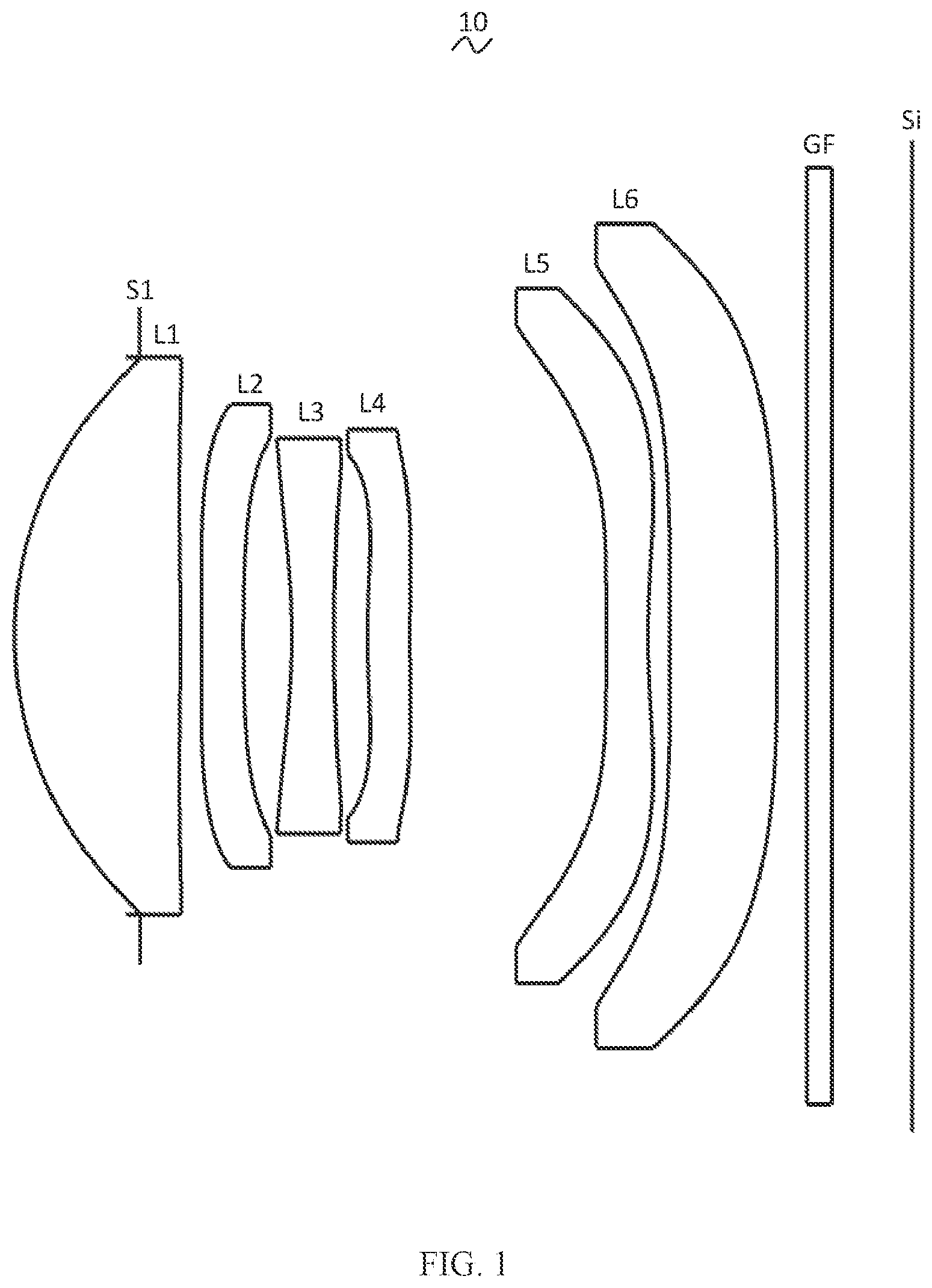
Referring to the accompanying drawings, the present disclosure provides a camera optical lens 10 . shows the camera optical lens 10 of the first embodiment of the present disclosure, the camera optical lens 10 includes six lenses. Specifically, the camera optical lens 10 includes, from an object side to an image side: an aperture S1, a first lens L 1 , a second lens L 2 , a third lens L 3 , a fourth lens L 4 , a fifth lens L 5 , and a sixth lens L 6 . An optical element, such as an optical filter GF, may be arranged between the sixth lens L 6 and an image surface Si.
In this embodiment, the first lens L 1 has a positive refractive power, the second lens L 2 has a negative refractive power, the third lens L 3 has a negative refractive power, the fourth lens L 4 has a positive refractive power, the fifth lens L 5 has a negative refractive power, and the sixth lens L 6 has a positive refractive power.
In this embodiment, the first lens L 1 is made of glass material, and the second lens L 2 , the third lens L 3 , the fourth lens L 4 , the fifth lens L 5 , and the sixth lens L 6 are all made of plastic material. In other embodiments, the lenses may also be made of other materials.
In this embodiment, a focal length of the camera optical lens 10 is defined as f, a focal length of the second lens L 2 is defined as f2, a central curvature radius of an object-side surface of the fifth lens L 5 is defined as R9, and a central curvature radius of an image-side surface of the fifth lens L 5 is defined as R10. The camera optical lens 10 satisfies a condition of: −5.00≤ f 2/ f≤− 2.00 (1) 3.00≤ R 9/ R 10≤20.00 (2)
Herein, the relational expression (1) specifies a ratio between the focal length f2 of the second lens L 2 , thus effectively balance system spherical aberration and field curvature within the range of the relational expression.
The relational expression (2) specifies a shape of the fifth lens L 5 . Within this range, the deflection of light passing through the lens can be eased and aberrations can be effectively reduced.
A focal length of the camera optical lens 10 is defined as f, and a focal length of the fourth lens L 4 is defined as f4. The camera optical lens 10 satisfies a condition of 1.50≤f4/f≤4.00, which specifies a ratio between the focal length f4 of the fourth lens L 4 and the focal length f of the camera optical lens 10 . In this way, the focal length is distributed appropriately, so that the camera optical lens can attain a better imaging quality and a lower sensitivity.
A central curvature radius of an object-side surface of the sixth lens L 6 is defined as R11, and a central curvature radius of an image-side surface of the sixth lens L 6 is defined as R12. The camera optical lens 10 satisfies a condition of R12/R11≤−1.50. The relationship expression specifies a shape of the fourth lens L 4 , thus facilitating correcting an off-axis aberration in this range.
In this embodiment, an object-side surface of the first lens L 1 is convex in the paraxial region, and an image-side surface of the first lens L 1 is convex in the paraxial region.
A focal length of the camera optical lens 10 is defined as f, and a focal length of the first lens L 1 is defined as f1. The camera optical lens 10 satisfies a condition of 0.24≤f1/f≤0.79. The relationship expression specifies a ratio between the focal length f1 of the first lens L 1 and the focal length f of the camera optical lens 10 . Within the range specified by the relationship expression, the first lens L 1 has an appropriate positive refractive power, thus facilitating reducing system aberration and a development towards a lens having a characteristics of ultra-thin and long focal length. Preferably, the camera optical lens 10 further satisfies a condition of 0.39≤f1/f≤0.63.
A central curvature radius of an object-side surface of the first lens L 1 is defined as R1, and a central curvature radius of an image-side surface of the first lens L 1 is defined as R2. The camera optical lens 10 satisfies a condition of −1.96≤(R1+R2)/(R1−R2)≤−0.54. By reasonably controlling a shape of the first lens L 1 , the first lens L 1 can effectively correct system spherical aberration. Preferably, the camera optical lens 10 satisfies a condition of −1.22≤(R1+R2)/(R1−R2)≤−0.68.
An on-axis thickness of the first lens L 1 is defined as d1, and a total optical length of the camera optical lens 10 is defined as TTL. The camera optical lens 10 satisfies a condition of 0.09≤d1/TTL≤0.28, conducing to realize an ultra-thin effect in this range. Preferably, the camera optical lens 10 further satisfies a condition of 0.15≤d1/TTL≤0.23.
In this embodiment, an object-side surface of the second lens L 2 is concave in the paraxial region, and an image-side surface of the second lens L 2 is concave in the paraxial region.
A central curvature radius of the object-side surface of the second lens L 2 is defined as R3, a central curvature radius of the image-side surface of the second lens L 2 is defined as R4, and the camera optical lens 10 further satisfies a condition of 0.25≤(R3+R4)/(R3−R4)≤3.99, which specifies a shape of the second lens L 2 . Within this range, a development towards ultra-thin and long focal length lenses would facilitate correcting the problem of an on-axis aberration. Preferably, the camera optical lens 10 further satisfies a condition of 0.41≤(R3+R4)/(R3−R4)≤3.19.
A total optical length of the camera optical lens 10 is defined as TTL, an on-axis thickness of the second lens L 2 is defined as d3, and the camera optical lens 10 satisfies a condition of 0.02≤d3/TTL≤0.07. Within this range, it is beneficial to achieve ultra-thin lenses. Preferably, the camera optical lens 10 further satisfies a condition of 0.03≤d3/TTL≤0.06.
In this embodiment, an object-side surface of the third lens L 3 is concave in the paraxial region, and an image-side surface of the third lens L 3 is concave in the paraxial region.
The focal length of the camera optical lens 10 is defined as f, a focal length of the third lens L 3 is defined as f3, and the camera optical lens 10 further satisfies a condition of −1.58≤f3/f≤−0.42. In this way, a negative refractive power of the third lens L 3 is distributed appropriately, so that the camera optical lens can attain a better imaging quality and a lower sensitivity. Preferably, the camera optical lens 10 further satisfies a condition of −0.99≤f3/f≤−0.52.
A central curvature radius of the object-side surface of the third lens L 3 is defined as R5, a central curvature radius of the image-side surface of the third lens L 3 is defined as R6, and the camera optical lens 10 further satisfies a condition of −1.27≤(R5+R6)/(R5−R6)≤−0.19, which specifies a shape of the third lens L 3 . Within this range, the deflection of light passing through the lens can be eased and aberrations can be effectively reduced. Preferably, the camera optical lens 10 further satisfies a condition of −0.80≤(R5+R6)/(R5−R6)≤−0.24.
The total optical length of the camera optical lens 10 is defined as TTL, an on-axis thickness of the third lens L 3 is defined as d5, and the camera optical lens 10 further satisfies a condition of 0.02≤d5/TTL≤0.07. This can facilitate achieving ultra-thin lenses. Preferably, the camera optical lens 10 further satisfies a condition of 0.04≤d5/TTL≤0.06.
In an embodiment, an object-side surface of the fourth lens L 4 is convex in the paraxial region, and an image-side surface of the fourth lens L 4 is concave in the paraxial region.
A curvature radius of the object-side surface of the fourth lens L 4 is defined as R7, a curvature radius of the image-side surface of the fourth lens L 4 is defined as R8, and the camera optical lens 10 satisfies a condition of −5.78≤(R7+R8)/(R7−R8)≤−1.18, which specifies a shape of the fourth lens L 4 . Within this range, a development towards ultra-thin lenses would facilitate correcting the problem of the off-axis aberration. Preferably, the camera optical lens 10 further satisfies a condition of −3.61≤(R7+R8)/(R7−R8)≤−1.47.
The total optical length of the camera optical lens 10 is defined as TTL, an on-axis thickness of the fourth lens L 4 is defined as d7, and the camera optical lens 10 satisfies a condition of 0.02≤d7/TTL≤0.07. Within this range, this can facilitate achieving ultra-thin lenses. Preferably, the camera optical lens 10 further satisfies a condition of 0.03≤d7/TTL≤0.06.
In an embodiment, an object-side surface of the fifth lens L 5 is convex in the paraxial region, and an image-side surface of the fifth lens L 5 is concave in the paraxial region.
The focal length of the camera optical lens 10 is defined as f, a focal length of the fifth lens L 5 is defined as f5, and the camera optical lens 10 further satisfies a condition of −3.31≤f5/f≤−0.85, which can effectively make a light angle of the camera optical lens 10 gentle and reduce a tolerance sensitivity. Preferably, the camera optical lens 10 further satisfies a condition of −2.07≤f5/f≤−1.06.
A central curvature radius of the object-side surface of the fifth lens L 5 is defined as R9, a central curvature radius of the image-side surface of the fifth lens L 5 is defined as R10, and the camera optical lens 10 further satisfies a condition of 0.55≤(R9+R10)/(R9−R10)≤2.96, which specifies a shape of the fifth lens L 5 . Within this range, a development towards ultra-thin and wide-angle lenses can facilitate correcting a problem of the off-axis aberration. Preferably, the camera optical lens 10 further satisfies a condition of 0.89≤(R9+R10)/(R9−R10)≤2.37.
The total optical length of the camera optical lens 10 is defined as TTL, an on-axis thickness of the fifth lens L 5 is defined as d9, and the camera optical lens 10 further satisfies a condition of 0.02≤d9/TTL≤0.07. Within this range, this can facilitate achieving ultra-thin lenses. Preferably, the camera optical lens 10 further satisfies a condition of 0.04≤d9/TTL≤0.06.
In this embodiment, an object-side surface of the sixth lens L 6 is convex in the paraxial region, and an image-side surface of the sixth lens L 6 is convex in the paraxial region. It can be understood that, in other embodiments, for the first lens L 1 , the second lens L 2 , the third lens L 3 , the fourth lens L 4 , the fifth lens L 5 , and the sixth lens L 6 , surface profiles of an object-side surface and an image-side surface respectively may be configured in other convex or concave arrangement.
A focal length of the camera optical lens 10 is defined as f, a focal length of the sixth lens L 6 is defined as f6, and the camera optical lens satisfies a condition of −27.26≤f6/f≤21.68. In this way, the focal length of the sixth lens L 6 is distributed appropriately, so that the system can attain a better imaging quality and a lower sensitivity. Preferably, the camera optical lens 10 further satisfies a condition of −17.04≤f6/f≤17.35.
A central curvature radius of the object-side surface of the sixth lens L 6 is defined as R11, a central curvature radius of the image-side surface of the sixth lens L 6 is defined as R12, and the camera optical lens 10 further satisfies a condition of −1.75≤(R11+R12)/(R11−R12)≤−0.14, which specifies a shape of the sixth lens L 6 . Within this range, a development towards ultra-thin lenses would facilitate correcting a problem like the off-axis aberration. Preferably, the camera optical lens 10 further satisfies a condition of −1.09≤(R11+R12)/(R11−R12)≤−0.17.
The total optical length of the camera optical lens 10 is defined as TTL, an on-axis thickness of the sixth lens L 6 is defined as d11, and the camera optical lens 10 further satisfies a condition of 0.06≤d11/TTL≤0.19. Within this range, this can facilitate achieving ultra-thin lenses. Preferably, the camera optical lens 10 further satisfies a condition of 0.10≤d11/TTL≤0.15.
In this embodiment, an image height of the camera optical lens 10 is defined as IH, the total optical length of the camera optical lens 10 is defined as TTL, and the camera optical lens 10 further satisfies a condition of TTL/IH≤2.15, thus facilitating to achieve ultra-thin lenses.
In this embodiment, an F number (FNO) of the camera optical lens 10 is less than or equal to 2.00, thus achieving a wide aperture and the camera optical lens has excellent imaging performance.
In this embodiment, the focal length of the camera optical lens 10 is defined as f, the image height of the camera optical lens 10 is defined as IH, and the camera optical lens 10 further satisfies a condition of f/IH≥2.25, thus achieving a long focal length and the camera optical lens has excellent imaging performance.
In this embodiment, the focal length of the camera optical lens 10 is defined as f, a combined focal length of the first lens L 1 and the second lens L 2 is defined as f12, and the camera optical lens 10 further satisfies a condition of 0.28≤f12/f≤0.87. Within this range, the aberration and distortion of the imaging optical lens 10 can be eliminated, and the focal length of the imaging optical lens 10 can be suppressed to maintain the miniaturization of the imaging lens system group. Preferably, the camera optical lens 10 further satisfies a condition of 0.45≤f12/f≤0.70.
When the above condition is satisfied, the camera optical lens 10 can meet the design requirements of wide-angle and ultra-thin in the case that a good optical performance is maintained. According to characteristics of the camera optical lens 10 , the camera optical lens 10 is particularly suitable for mobile phone camera lens components and WEB camera lenses composed of camera elements such as CCD and CMOS with high pixel.
In the following, examples will be used to describe the camera optical lens 10 of the present disclosure. The symbols recorded in each example will be described as follows. The focal length, on-axis distance, central curvature radius, on-axis thickness, inflexion point position, and arrest point position are all in units of mm.
TTL refers to a total optical length (an on-axis distance from an object-side surface of the first lens L 1 to an image surface Si) in units of mm.
Aperture value FNO refers to a ratio of an effective focal length of the camera optical lens to an entrance pupil diameter.
Preferably, inflexion points and/or arrest points can be arranged on the object-side surface and/or the image-side surface of the lens, so as to satisfy the demand for high quality imaging. The description below may be referred for specific implementations.
The design data of the camera optical lens 10 in the first embodiment of the present disclosure are shown in Table 1.
TABLE 1
R d nd vd
S1 ∞ d0 = −1.045
R1 2.191 d1 = 1.386 nd1 1.5267 v1 76.60
R2 −21.348 d2 = 0.172
R3 −37.577 d3 = 0.350 nd2 1.5661 v2 37.71
R4 12.307 d4 = 0.406
R5 −4.783 d5 = 0.350 nd3 1.6153 v3 25.94
R6 8.645 d6 = 0.283
R7 5.095 d7 = 0.350 nd4 1.6700 v4 19.39
R8 13.472 d8 = 1.641
R9 57.479 d9 = 0.350 nd5 1.5444 v5 55.82
R10 4.998 d10 = 0.180
R11 63.176 d11 = 0.894 nd6 1.6701 v6 19.39
R12 −947.646 d12 = 0.250
R13 ∞ d13 = 0.210 ndg 1.5168 vg 64.17
R14 ∞ d14 = 0.668
In the table, meanings of various symbols will be described as follows:
•
• S1: aperture; • R: curvature radius at a center of an optical surface; • R1: central curvature radius of the object-side surface of the first lens L 1 ; • R2: central curvature radius of the image-side surface of the first lens L 1 ; • R3: central curvature radius of the object-side surface of the second lens L 2 ; • R4: central curvature radius of the image-side surface of the second lens L 2 ; • R5: central curvature radius of the object-side surface of the third lens L 3 ; • R6: central curvature radius of the image-side surface of the third lens L 3 ; • R7: central curvature radius of the object-side surface of the fourth lens L 4 ; • R8: central curvature radius of the image-side surface of the fourth lens L 4 ; • R9: central curvature radius of the object-side surface of the fifth lens L 5 ; • R10: central curvature radius of the image-side surface of the fifth lens L 5 ; • R11: central curvature radius of the object-side surface of the sixth lens L 6 ; • R12: central curvature radius of the image-side surface of the sixth lens L 6 ; • R13: central curvature radius of an object-side surface of the optical filter GF; • R14: central curvature radius of an image-side surface of the optical filter GF; • d: on-axis thickness of a lens, or an on-axis distance between lenses; • d0: on-axis distance from the aperture S1 to the object-side surface of the first lens L 1 ; • d1: on-axis thickness of the first lens L 1 ; • d2: on-axis distance from the image-side surface of the first lens L 1 to the object-side surface of the second lens L 2 ; • d3: on-axis thickness of the second lens L 2 ; • d4: on-axis distance from the image-side surface of the second lens L 2 to the object-side surface of the third lens L 3 ; • d5: on-axis thickness of the third lens L 3 ; • d6: on-axis distance from the image-side surface of the third lens L 3 to the object-side surface of the fourth lens L 4 ; • d7: on-axis thickness of the fourth lens L 4 ; • d8: on-axis distance from the image-side surface of the fourth lens L 4 to the object-side surface of the fifth lens L 5 ; • d9: on-axis thickness of the fifth lens L 5 ; • d10: on-axis distance from the image-side surface of the fifth lens L 5 to the object-side surface of the sixth lens L 6 ; • d11: on-axis thickness of the sixth lens L 6 ; • d12: on-axis distance from the image-side surface of the sixth lens L 6 to the object-side surface of the optical filter GF; • d13: on-axis thickness of the optical filter GF; • d14: on-axis distance from the image-side surface of the optical filter GF to the image surface S1; • nd: refractive index of a d line; • nd1: refractive index of the d line of the first lens L 1 ; • nd2: refractive index of the d line of the second lens L 2 ; • nd3: refractive index of the d line of the third lens L 3 ; • nd4: refractive index of the d line of the fourth lens L 4 ; • nd5: refractive index of the d line of the fifth lens L 5 ; • nd6: refractive index of the d line of the sixth lens L 6 ; • ndg: refractive index of the d line of the optical filter GF; • vd: abbe number; • v1: abbe number of the first lens L 1 ; • v2: abbe number of the second lens L 2 ; • v3: abbe number of the third lens L 3 ; • v4: abbe number of the fourth lens L 4 ; • v5: abbe number of the fifth lens L 5 ; • v6: abbe number of the sixth lens L 6 ; • vg: abbe number of the optical filter GF.
Table 2 shows aspherical surface data of the camera optical lens 10 in the first embodiment of the present disclosure.
TABLE 2
Conic
coefficient Aspheric surface coefficients
k A4 A6 A8 A10 A12
R1 0.0000E+00 −2.2478E−03 4.5667E−04 −2.3357E−03 2.7593E−03 −2.0319E−03
R2 −9.9000E+01 1.4819E−02 −5.4749E−04 −2.6983E−03 1.2525E−03 −2.8049E−04
R3 −9.8331E+01 3.1261E−02 8.3510E−03 −8.0760E−03 5.4063E−04 3.7315E−03
R4 5.1344E+01 7.4699E−03 2.4706E−02 −3.5801E−04 −3.1199E−02 4.2410E−02
R5 8.2992E+00 −2.1082E−02 1.4527E−01 −1.9118E−01 1.7331E−01 −1.1172E−01
R6 −9.9000E+01 −7.7233E−02 2.0305E−01 −2.7631E−01 2.8350E−01 −2.3012E−01
R7 −3.1403E+00 −1.3368E−01 4.7162E−02 1.4002E−02 −1.1188E−01 1.5993E−01
R8 3.3586E+01 −6.2422E−02 −7.9866E−03 5.6015E−02 −9.7962E−02 9.8192E−02
R9 9.9000E+01 −6.4884E−02 6.0327E−03 −5.4991E−04 1.4016E−03 −8.0118E−04
R10 2.5898E+00 −7.4788E−02 1.4686E−02 −1.8932E−03 −6.2950E−04 2.9295E−04
R11 9.7378E+01 −3.3898E−02 1.7277E−02 −6.1887E−03 1.0895E−03 −1.0230E−04
R12 9.9000E+01 −3.3144E−02 1.0791E−02 −2.9512E−03 5.9252E−04 −1.0618E−04
Conic
coefficient Aspheric surface coefficients
k A14 A16 A18 A20
R1 0.0000E+00 8.8211E−04 −2.2807E−04 3.1882E−05 −1.8800E−06
R2 −9.9000E+01 3.6330E−05 −2.7444E−06 1.1140E−07 −1.8680E−09
R3 −9.8331E+01 −2.8393E−03 1.0346E−03 −1.8841E−04 1.3593E−05
R4 5.1344E+01 −2.6463E−02 7.5010E−03 −2.5129E−04 −2.1846E−04
R5 8.2992E+00 4.9393E−02 −1.3703E−02 2.0692E−03 −1.2645E−04
R6 −9.9000E+01 1.3446E−01 −5.1237E−02 1.0951E−02 −9.6988E−04
R7 −3.1403E+00 −1.3344E−01 6.8011E−02 −2.0055E−02 2.6351E−03
R8 3.3586E+01 −6.0664E−02 2.2719E−02 −4.5893E−03 3.7636E−04
R9 9.9000E+01 2.0028E−04 −2.4909E−05 1.5181E−06 −3.6343E−08
R10 2.5898E+00 −4.8995E−05 4.0381E−06 −1.6196E−07 2.5091E−09
R11 9.7378E+01 5.4303E−06 −1.6387E−07 2.6273E−09 −1.7422E−11
R12 9.9000E+01 1.5294E−05 −1.4816E−06 8.2356E−08 −1.9467E−09
Here, K is a conic coefficient, and A4, A6, A8, A10, A12, A14, A16, A18 and A20 are aspheric surface coefficients. y =( x 2 /R )/{1+[1−( k+ 1)( x 2 /R 2 )] 1/2 }+A 4 x 4 +A 6 x 6 +A 8 x 8 +A 10 x 10 +A 12 x 12 +A 14 x 14 +A 16 x 16 +A 18 x 18 +A 20 x 20 (3)
Here, x denotes a vertical distance between a point on an aspheric curve and an optical axis, and y denotes a depth of a aspheric surface (i.e. a vertical distance between a point on an aspheric surface that is x away from the optical axis, and a tangent plane tangent to an vertex of the optical axis on the aspheric surface).
For convenience, an aspheric surface of each lens surface uses the aspheric surfaces shown in the above formula (3). However, the present disclosure is not limited to the aspherical polynomials form shown in the formula (3).
Table 3 and Table 4 show design data of inflexion points and arrest points of the camera optical lens 10 according to the first embodiment of the present disclosure. P1R1 and P1R2 respectively represent the object-side surface and the image-side surface of the first lens L 1 , P2R1 and P2R2 respectively represent the object-side surface and the image-side surface of the second lens L 2 , P3R1 and P3R2 respectively represent the object-side surface and the image-side surface of the third lens L 3 , P4R1 and P4R2 respectively represent the object-side surface and the image-side surface of the fourth lens L 4 , P5R1 and P5R2 respectively represent the object-side surface and the image-side surface of the fifth lens L 5 , P6R1 and P6R2 respectively represent the object-side surface and the image-side surface of the sixth lens L 6 . The data in the column named “inflexion point position” refer to vertical distances from inflexion points arranged on each lens surface to the optic axis of the camera optical lens 10 . The data in the column named “arrest point position” refer to vertical distances from arrest points arranged on each lens surface to the optical axis of the camera optical lens 10 .
TABLE 3
Number(s) of Inflexion point Inflexion point
inflexion points position 1 position 2
P1R1 0 / /
P1R2 1 0.515 /
P2R1 1 0.265 /
P2R2 1 1.375 /
P3R1 2 0.785 1.225
P3R2 1 1.015 /
P4R1 1 0.375 /
P4R2 2 0.325 1.285
P5R1 2 0.155 2.005
P5R2 2 0.525 2.435
P6R1 2 0.205 2.505
P6R2 1 2.895 /
TABLE 4
Number(s) of Arrest point
arrest points position 1
P1R1 0 /
P1R2 1 0.975
P2R1 1 0.445
P2R2 0 /
P3R1 0 /
P3R2 1 1.235
P4R1 1 0.665
P4R2 1 0.565
P5R1 1 0.265
P5R2 1 0.955
P6R1 1 0.355
P6R2 0 /
and illustrate a longitudinal aberration and a lateral color of light with wavelengths of 430 nm, 470 nm, 510 nm, 555 nm, 610 nm and 650 nm after passing the camera optical lens 10 according to the first embodiment, respectively. illustrates a field curvature and a distortion of light with a wavelength of 555 nm after passing the camera optical lens 10 according to the first embodiment. In , a field curvature S is a field curvature in a sagittal direction, and T is a field curvature in a meridional direction.
Table 13 in the following shows various values of first, second and third embodiments and values corresponding to parameters which are specified in the above conditions.
As shown in Table 13, the first embodiment satisfies the above conditions.
In this Embodiment, an entrance pupil diameter (ENPD) of the camera optical lens is 3.946 mm, an image height (IH) of 1.0H is 3.500 mm, a field of view (FOV) in a diagonal direction is 47.000. Thus, the camera optical lens meets the design requirements of large aperture, long focal length and ultra-thin. Its on-axis and off-axis aberrations are fully corrected, thereby achieving excellent optical characteristics.
Second Embodiment
shows a camera optical lens 20 of the second embodiment of the present disclosure, the second embodiment is basically the same as the first embodiment and involves symbols having the same meanings as the first embodiment, and only differences therebetween will be described in the following.
In this embodiment, the object-side surface of the second lens L 2 is convex in the paraxial region.
Table 5 shows design data of the camera optical lens 20 in the second embodiment of the present disclosure.
TABLE 5
R d nd vd
S1 ∞ d0 = −1.054
R1 2.189 d1 = 1.387 nd1 1.5267 v1 76.60
R2 −126.026 d2 = 0.216
R3 26.996 d3 = 0.350 nd2 1.5661 v2 37.71
R4 9.885 d4 = 0.366
R5 −4.750 d5 = 0.355 nd3 1.6153 v3 25.94
R6 21.362 d6 = 0.414
R7 15.256 d7 = 0.350 nd4 1.6700 v4 19.39
R8 55.096 d8 = 1.477
R9 11.820 d9 = 0.350 nd5 1.5444 v5 55.82
R10 3.876 d10 = 0.195
R11 128.087 d11 = 0.948 nd6 1.6701 v6 19.39
R12 −193.400 d12 = 0.250
R13 ∞ d13 = 0.210 ndg 1.5168 vg 64.17
R14 ∞ d14 = 0.621
Table 6 shows aspherical surface data of each lens of the camera optical lens 20 in the second embodiment of the present disclosure.
TABLE 6
Conic
coefficient Aspheric surface coefficients
k A4 A6 A8 A10 A12
R1 0.0000E+00 −2.0191E−03 2.0079E−04 −1.5596E−03 1.7851E−03 −1.3155E−03
R2 −9.9000E+01 8.3926E−03 −1.5859E−03 −4.8268E−04 2.2104E−04 −4.0672E−05
R3 9.9000E+01 1.3592E−02 3.9773E−03 5.7664E−04 −3.8635E−03 4.3431E−03
R4 3.7540E+00 1.4918E−03 1.4667E−02 1.0899E−02 −2.8632E−02 3.0584E−02
R5 8.4566E+00 1.1413E−02 7.0105E−02 −8.4329E−02 7.6520E−02 −5.4104E−02
R6 −9.4101E+01 −1.7489E−02 8.0856E−02 −9.8440E−02 9.4344E−02 −8.2806E−02
R7 −4.3667E+00 −1.0892E−01 3.4802E−03 5.8425E−02 −1.5807E−01 2.0773E−01
R8 −9.9000E+01 −7.0354E−02 −9.7664E−04 4.4498E−02 −8.4124E−02 8.8048E−02
R9 −1.8726E+01 −6.4304E−02 −1.2832E−03 6.7147E−03 −1.9156E−03 1.9617E−04
R10 3.4907E−01 −6.1247E−02 3.5307E−03 3.7955E−03 −2.2233E−03 5.8680E−04
R11 9.9000E+01 −1.7556E−02 9.1994E−03 −3.7262E−03 6.4831E−04 −5.7664E−05
R12 −9.9000E+01 −2.8404E−02 6.1378E−03 −2.8229E−04 −2.9645E−04 7.7718E−05
Conic
coefficient Aspheric surface coefficients
k A14 A16 A18 A20
R1 0.0000E+00 5.6512E−04 −1.4446E−04 1.9878E−05 −1.1710E−06
R2 −9.9000E+01 4.5486E−06 −3.1169E−07 1.1659E−08 −1.7925E−10
R3 9.9000E+01 −2.4583E−03 8.1130E−04 −1.4015E−04 9.6573E−06
R4 3.7540E+00 −1.6883E−02 3.7727E−03 4.2169E−04 −2.5819E−04
R5 8.4566E+00 2.7055E−02 −8.3548E−03 1.3588E−03 −8.6578E−05
R6 −9.4101E+01 5.3920E−02 2.2575E−02 5.1445E−03 −4.7221E−04
R7 −4.3667E+00 −1.7125E−01 8.6576E−02 −2.5079E−02 3.2278E−03
R8 −9.9000E+01 −5.5811E−02 2.1077E−02 −4.2343E−03 3.4255E−04
R9 −1.8726E+01 8.2072E−06 −3.5265E−06 2.7920E−07 −7.3811E−09
R10 3.4907E−01 −8.5701E−05 7.0094E−06 −2.9759E−07 5.0842E−09
R11 9.9000E+01 2.8622E−06 −8.0410E−08 1.1980E−09 −7.3731E−12
R12 −9.9000E+01 −8.7437E−06 4.4882E−07 −4.7730E−09 −2.4922E−10
Table 7 and table 8 show design data of inflexion points and arrest points of each lens of the camera optical lens 20 lens according to the second embodiment of the present disclosure.
TABLE 7
Number(s) of Inflexion point Inflexion point
inflexion points position 1 position 2
P1R1 1 1.935 /
P1R2 2 0.295 1.305
P2R1 0 / /
P2R2 1 1.345 /
P3R1 2 0.755 1.195
P3R2 1 1.055 /
P4R1 1 0.225 /
P4R2 2 0.155 1.315
P5R1 2 0.335 2.055
P5R2 1 0.645 /
P6R1 2 0.205 2.635
P6R2 1 2.915 /
TABLE 8
Number of Arrest point Arrest point
arrest points position 1 position 2
P1R1 0 / /
P1R2 2 0.505 1.735
P2R1 0 / /
P2R2 0 / /
P3R1 0 / /
P3R2 1 1.275 /
P4R1 1 0.395 /
P4R2 1 0.255 /
P5R1 1 0.575 /
P5R2 1 1.195 /
P6R1 1 0.345 /
P6R2 0 / /
and illustrate a longitudinal aberration and a lateral color of light with wavelengths of 430 nm, 470 nm, 510 nm, 555 nm, 610 nm and 650 nm after passing the camera optical lens 20 according to the second embodiment, respectively. illustrates a field curvature and a distortion of light with a wavelength of 555 nm after passing the camera optical lens 20 according to the second embodiment. In , a field curvature S is a field curvature in a sagittal direction, and T is a field curvature in a meridional direction.
As shown in Table 13, the second embodiment satisfies the above conditions.
In this Embodiment, an entrance pupil diameter (ENPD) of the camera optical lens 20 is 3.946 mm, an image height (IH) of 1.0H is 3.500 mm, a field of view (FOV) in a diagonal direction is 47.00°. Thus, the camera optical lens 20 meets the design requirements of large aperture, long focal length and ultra-thin. Its on-axis and off-axis aberrations are fully corrected, thereby achieving excellent optical characteristics.
Third Embodiment
shows a camera optical lens 30 of the third embodiment of the present disclosure, the third embodiment is basically the same as the first embodiment and involves symbols having the same meanings as the first embodiment, and only differences therebetween will be described in the following.
In this embodiment, the object-side surface of the second lens L 2 is convex in the paraxial region. The object-side surface of the sixth lens L 6 is concave in the paraxial region, and the image-side surface of the sixth lens L 6 is concave in the paraxial region. The sixth lens L 6 has a negative refractive power.
Table 9 shows design data of the camera optical lens 30 in the third embodiment of the present disclosure.
TABLE 9
R d nd vd
S1 ∞ d0 = −1.025
R1 2.205 d1 = 1.412 nd1 1.5267 v1 76.60
R2 −205.718 d2 = 0.196
R3 26.322 d3 = 0.321 nd2 1.5661 v2 37.71
R4 11.930 d4 = 0.368
R5 −4.501 d5 = 0.368 nd3 1.6153 v3 25.94
R6 16.169 d6 = 0.391
R7 7.817 d7 = 0.320 nd4 1.6700 v4 19.39
R8 16.097 d8 = 1.574
R9 131.830 d9 = 0.330 nd5 1.5444 v5 55.82
R10 6.761 d10 = 0.148
R11 −87.365 d11 = 0.925 nd6 1.6701 v6 19.39
R12 436.824 d12 = 0.250
R13 ∞ d13 = 0.210 ndg 1.5168 vg 64.17
R14 ∞ d14 = 0.677
Table 10 shows aspherical surface data of each lens of the camera optical lens 30 in the third embodiment of the present disclosure.
TABLE 10
Conic
coefficient Aspheric surface coefficients
k A4 A6 A8 A10 A12
R1 0.0000E+00 −2.2473E−03 3.9553E−04 −1.9520E−03 2.1242E−03 −1.5168E−03
R2 9.9000E+01 5.1161E−03 −6.7191E−04 −8.5498E−04 3.7453E−04 −7.5663E−05
R3 9.5764E+01 1.0351E−02 7.2409E−03 −1.9299E−03 −1.3538E−03 2.6209E−03
R4 1.8861E+01 3.8414E−03 1.6140E−02 8.2512E−03 −2.6701E−02 3.1575E−02
R5 7.2704E+00 2.5096E−02 5.8801E−02 −7.6895E−02 6.9130E−02 −4.5668E−02
R6 −9.8728E+01 −1.1886E−02 7.9664E−02 −1.1017E−01 1.1787E−01 −1.0748E−01
R7 1.8389E+01 −1.1675E−01 −2.3115E−03 7.5929E−02 −2.0159E−01 2.7074E−01
R8 −9.8538E+01 −6.8022E−02 −1.0446E−02 6.1430E−02 −1.1242E−01 1.1827E−01
R9 9.9000E+01 −4.6121E−02 −1.3629E−02 1.2305E−02 −3.8383E−03 6.3842E−04
R10 4.5586E+00 −2.6432E−02 −1.5858E−02 1.1597E−02 −4.5995E−03 1.0928E−03
R11 −9.9000E+01 −5.3177E−03 3.3849E−03 −2.2446E−03 4.2165E−04 −3.6436E−05
R12 −9.9000E+01 −2.6111E−02 5.7311E−03 −6.1357E−04 −1.0065E−04 2.6374E−05
Conic
coefficient Aspheric surface coefficients
k A14 A16 A18 A20
R1 0.0000E+00 6.4181E−04 −1.6276E−04 2.2270E−05 −1.2886E−06
R2 9.9000E+01 8.9216E−06 −6.1661E−07 2.2822E−08 −3.4651E−10
R3 9.5764E+01 −1.7217E−03 6.3402E−04 −1.1930E−04 8.7968E−06
R4 1.8861E+01 −2.0205E−02 6.6580E−03 −7.3415E−04 −7.4375E−05
R5 7.2704E+00 2.1039E−02 −6.0100E−03 9.0682E−04 −5.3349E−05
R6 −9.8728E+01 6.9783E−02 −2.8666E−02 6.3895E−03 −5.7498E−04
R7 1.8389E+01 −2.2729E−01 1.1692E−01 −3.4307E−02 4.4460E−03
R8 −9.8538E+01 −7.5724E−02 2.8848E−02 −5.8434E−03 4.7699E−04
R9 9.9000E+01 −5.4445E−05 1.7427E−06 3.5988E−08 −2.6112E−09
R10 4.5586E+00 −1.5543E−04 1.2792E−05 −5.5598E−07 9.8229E−09
R11 −9.9000E+01 1.6911E−06 −4.3704E−08 5.9455E−10 −3.3306E−12
R12 −9.9000E+01 −8.8024E−07 −2.7576E−07 3.2541E−08 −1.0731E−09
Table 11 and Table 12 show design data inflexion points and arrest points of the respective lenses in the camera optical lens 30 according to the third embodiment of the present disclosure.
TABLE 11
Number(s) of Inflexion point Inflexion point
inflexion points position 1 position 2
P1R1 1 1.925 /
P1R2 2 0.295 1.165
P2R1 0 / /
P2R2 1 1.365 /
P3R1 2 0.725 1.225
P3R2 1 1.055 /
P4R1 1 0.315 /
P4R2 2 0.275 1.305
P5R1 2 0.125 2.025
P5R2 1 0.615 /
P6R1 1 2.585 /
P6R2 2 0.095 2.905
TABLE 12
Number of Arrest point Arrest point
arrest points position 1 position 2
P1R1 0 / /
P1R2 2 0.505 1.505
P2R1 0 / /
P2R2 0 / /
P3R1 0 / /
P3R2 1 1.275 /
P4R1 1 0.545 /
P4R2 1 0.465 /
P5R1 1 0.205 /
P5R2 1 1.055 /
P6R1 0 / /
P6R2 1 0.145 /
and illustrate a longitudinal aberration and a lateral color of light with wavelengths of 430 nm, 470 nm, 510 nm, 555 nm, 610 nm and 650 nm after passing the camera optical lens 30 according to the third embodiment, respectively. illustrates a field curvature and a distortion of light with a wavelength of 555 nm after passing the camera optical lens 30 according to the third embodiment. In , a field curvature S is a field curvature in a sagittal direction, and T is a field curvature in a meridional direction.
As shown in Table 13, the third embodiment satisfies the above conditions.
In this Embodiment, an entrance pupil diameter (ENPD) of the camera optical lens 30 is 3.946 mm, an image height (IH) of 1.0H is 3.500 mm, a field of view (FOV) in a diagonal direction is 47.00°. Thus, the camera optical lens 30 meets the design requirements of large aperture, long focal length and ultra-thin. Its on-axis and off-axis aberrations are fully corrected, thereby achieving excellent optical characteristics.
Table 13 in the following lists values corresponding to the respective conditions in the first, second and third embodiment according to the above conditions, as well as values of other related parameters.
TABLE 13
Parameters Fist Second Third
and conditions embodiment embodiment embodiment
f 7.891 7.892 7.892
f1 3.842 4.090 4.142
f2 −16.257 −27.621 −38.669
f3 −4.921 −6.240 −5.645
f4 11.916 31.091 22.131
f5 −10.046 −10.724 −13.059
f6 87.613 114.078 −107.580
f12 4.594 4.520 4.447
FNO 2.00 2.00 2.00
TTL 7.490 7.489 7.490
IH 3.500 3.500 3.500
FOV 47.00° 47.00° 47.00°
f2/f −2.06 −3.50 −4.90
R9/R10 11.50 3.05 19.50
It can be appreciated by one having ordinary skill in the art that the description above is only embodiments of the present disclosure. In practice, one having ordinary skill in the art can make various modifications to these embodiments in forms and details without departing from the scope of the present disclosure.
Figures (9)
Citations
This patent cites (8)
- US20150268448
- US20160103298
- US20160170182
- US20160341934
- US20170307855
- US20180188496
- US108469668
- US2019086526