Abstract
A camera optical lens is provided. The camera optical lens includes, from an object side to an image side, a first lens, a second lens having a negative refractive power, a third lens, a fourth lens, a fifth lens, a sixth lens, a seventh lens, an eighth lens, and a ninth lens. The camera optical lens satisfies following conditions: 0.60≤f1/f≤1.80; and 1.50≤d11/d12≤8.00, where f denotes a focal length of the camera optical lens, f1 denotes a focal length of the first lens, d11 denotes an on-axis thickness of the sixth lens, and d12 denotes an on-axis distance from an image side surface of the sixth lens to an object side surface of the seventh lens. The camera optical lens according to the present disclosure satisfies design requirements for large-aperture, wide-angle, and ultra-thin lenses while achieving good optical performance.
Claims (10)
1. A camera optical lens, comprising, from an object side to an image side: a first lens; a second lens having a negative refractive power; a third lens; a fourth lens; a fifth lens; a sixth lens; a seventh lens; an eighth lens; and a ninth lens, wherein the camera optical lens satisfies following conditions: 0.60≤ f 1/ f≤ 1.80; 1.50≤ d 11/ d 12≤8.00; and ( R 11+ R 12)/( R 11− R 12)≤−4.50, where f denotes a focal length of the camera optical lens, f1 denotes a focal length of the first lens, d11 denotes an on-axis thickness of the sixth lens, d12 denotes an on-axis distance from an image side surface of the sixth lens to an object side surface of the seventh lens, R11 denotes a central curvature radius of an object side surface of the sixth lens, and R12 denotes a central curvature radius of the image side surface of the sixth lens.
Show 9 dependent claims
2. The camera optical lens as described in claim 1 , further satisfying following conditions: −3.16≤( R 1+ R 2)/( R 1− R 2)≤−0.42; and 0.03≤ d 1/ TTL≤ 0.21, where R1 denotes a central curvature radius of an object side surface of the first lens, R2 denotes a central curvature radius of an image side surface of the first lens, d1 denotes an on-axis thickness of the first lens, and TTL denotes a total optical length from the object side surface of the first lens to an image plane of the camera optical lens along an optic axis.
3. The camera optical lens as described in claim 1 , further satisfying following conditions: −5.10≤ f 2/ f≤− 0.62; 0.68≤( R 3+ R 4)/( R 3− R 4)≤7.37; and 0.02≤ d 3/ TTL≤ 0.12, where f2 denotes a focal length of the second lens, R3 denotes a central curvature radius of an object side surface of the second lens, R4 denotes a central curvature radius of an image side surface of the second lens, d3 denotes an on-axis thickness of the second lens, and TTL denotes a total optical length from an object side surface of the first lens to an image plane of the camera optical lens along an optic axis.
4. The camera optical lens as described in claim 1 , further satisfying following conditions: 1.02≤ f 3/ f 3≤3.90; −2.75≤( R 5+ R 6)/( R 5− R 6)≤0.73; and 0.02≤ d 5/ TTL≤ 0.09, where f3 denotes a focal length of the third lens, R5 denotes a central curvature radius of an object side surface of the third lens, R6 denotes a central curvature radius of an image side surface of the third lens, d5 denotes an on-axis thickness of the third lens, and TTL denotes a total optical length from an object side surface of the first lens to an image plane of the camera optical lens along an optic axis.
5. The camera optical lens as described in claim 1 , further satisfying following conditions: −66.71≤ f 4/ f≤ 14.76; −32.25≤( R 7+ R 8)/( R 7− R 8)≤3.58; and 0.02≤ d 7/ TTL≤ 0.08, where f4 denotes a focal length of the fourth lens, R7 denotes a central curvature radius of an object side surface of the fourth lens, R8 denotes a central curvature radius of an image side surface of the fourth lens, d7 denotes an on-axis thickness of the fourth lens, and TTL denotes a total optical length from an object side surface of the first lens to an image plane of the camera optical lens along an optic axis.
6. The camera optical lens as described in claim 1 , further satisfying following conditions: −62.10≤ f 5/ f≤ 18.50; −9.02≤( R 9+ R 10)/( R 9− R 10)≤0.50; and 0.02≤ d 9/ TTL≤ 0.07, where f5 denotes a focal length of the fifth lens, R9 denotes a central curvature radius of an object side surface of the fifth lens, R10 denotes a central curvature radius of an image side surface of the fifth lens, d9 denotes an on-axis thickness of the fifth lens, and TTL denotes a total optical length from an object side surface of the first lens to an image plane of the camera optical lens along an optic axis.
7. The camera optical lens as described in claim 1 , further satisfying following conditions: −29.24≤ f 6/ f≤ 127.61; and 0.02≤ d 11/ TTL≤ 0.09, where f6 denotes a focal length of the sixth lens, and TTL denotes a total optical length from an object side surface of the first lens to an image plane of the camera optical lens along an optic axis.
8. The camera optical lens as described in claim 1 , further satisfying following conditions: −12.99≤ f 7/ f≤ 38.81; −411.05≤( R 13+ R 14)/( R 13− R 14)≤8.17; and 0.02≤ d 13/ TTL≤ 0.11, where f7 denotes a focal length of the seventh lens, R13 denotes a central curvature radius of the object side surface of the seventh lens, R14 denotes a central curvature radius of an image side surface of the seventh lens, d13 denotes an on-axis thickness of the seventh lens, and TTL denotes a total optical length from an object side surface of the first lens to an image plane of the camera optical lens along an optic axis.
9. The camera optical lens as described in claim 1 , further satisfying following conditions: 0.68≤ f 8/ f≤ 2.67; −4.80( R 15+ R 16)/( R 15− R 16)≤−1.15; and 0.04≤ d 15/ TTL≤ 0.16, where f8 denotes a focal length of the eighth lens, R15 denotes a central curvature radius of an object side surface of the eighth lens, R16 denotes a central curvature radius of an image side surface of the eighth lens, d15 denotes an on-axis thickness of the eighth lens, and TTL denotes a total optical length from an object side surface of the first lens to an image plane of the camera optical lens along an optic axis.
10. The camera optical lens as described in claim 1 , further satisfying following conditions: −2.08≤ f 9/ f≤− 0.58; 0.29≤( R 17+ R 18)/( R 17− R 18)≤2.32; and 0.04≤ d 17/ TTL≤ 0.16, where f9 denotes a focal length of the ninth lens, R17 denotes a central curvature radius of an object side surface of the ninth lens, R18 denotes a central curvature radius of an image side surface of the ninth lens, d17 denotes an on-axis thickness of the ninth lens, and TTL denotes a total optical length from an object side surface of the first lens to an image plane of the camera optical lens along an optic axis.
Full Description
Show full text →
TECHNICAL FIELD
The present disclosure relates to the field of optical lenses, and in particular, to a camera optical lens applicable to portable terminal devices such as smart phones or digital cameras, and camera devices such as monitors or PC lenses.
BACKGROUND
With the emergence of smart phones in recent years, the demand for miniature camera lens has been increased. However, a photosensitive device of general camera lens is either a Charge Coupled Device (CCD) or a Complementary Metal-Oxide Semiconductor Sensor (CMOS Sensor). With the progress of the semiconductor manufacturing technology, the pixel size of the photosensitive device becomes smaller. In addition, the current electronic products have been developed to have better functions and lighter and smaller dimensions. Therefore, a miniature camera lens with good imaging quality has already become a mainstream in the current market.
In order to obtain better imaging quality, a traditional lens equipped in a mobile phone camera usually adopts a three-piece or four-piece structure, or even five-piece or six-piece structure. However, with the development of technologies and the increase of the various demands of users, a nine-piece structure gradually appears in lens designs as the pixel area of the photosensitive devices is constantly reduced and the requirement of the system on the imaging quality is constantly improved. Although the common nine-piece lens already has better optical performance, its settings on refractive power, lens spacing, and lens shape are still unreasonable to some extent. As a result, the lens structure cannot meet design requirements for ultra-thin, wide-angle lenses having a big aperture while achieving a good optical performance.
SUMMARY
In view of the above problems, the present disclosure provides a camera optical lens, which meets design requirements for large aperture, ultra-thinness and wide angle while achieving good optical performance.
In an embodiment, the present disclosure provides a camera optical lens. The camera optical lens includes, from an object side to an image side, a first lens, a second lens having a negative refractive power, a third lens, a fourth lens, a fifth lens, a sixth lens, a seventh lens, an eighth lens, and a ninth lens.
The camera optical lens satisfies following conditions: 0.60≤f1/f≤1.80; and 1.50≤d11/d12≤8.00, where f denotes a focal length of the camera optical lens, f1 denotes a focal length of the first lens, d11 denotes an on-axis thickness of the sixth lens, and d12 denotes an on-axis distance from an image side surface of the sixth lens to an object side surface of the seventh lens.
As an improvement, the camera optical lens further satisfies a condition of (R11+R12)/(R11−R12)≤−4.50, where R11 denotes a central curvature radius of an object side surface of the sixth lens, and R12 denotes a central curvature radius of the image side surface of the sixth lens.
As an improvement, the camera optical lens further satisfies following conditions: −3.16≤(R1+R2)/(R1−R2)≤−0.42; and 0.03≤d1/TTL≤0.21, where R1 denotes a central curvature radius of an object side surface of the first lens, R2 denotes a central curvature radius of an image side surface of the first lens, d1 denotes an on-axis thickness of the first lens, and TTL denotes a total optical length from the object side surface of the first lens to an image plane of the camera optical lens along an optic axis.
As an improvement, the camera optical lens further satisfies following conditions: −5.10≤f2/f≤−0.62; 0.68≤(R3+R4)/(R3−R4)≤7.37; and 0.02≤d3/TTL≤0.12, where f2 denotes a focal length of the second lens, R3 denotes a central curvature radius of an object side surface of the second lens, R4 denotes a central curvature radius of an image side surface of the second lens, d3 denotes an on-axis thickness of the second lens, and TTL denotes a total optical length from an object side surface of the first lens to an image plane of the camera optical lens along an optic axis.
As an improvement, the camera optical lens further satisfies following conditions: 1.02≤f3/f≤3.90; −2.75≤(R5+R6)/(R5−R6)≤0.73; and 0.02≤d5/TTL≤0.09, where f3 denotes a focal length of the third lens, R5 denotes a central curvature radius of an object side surface of the third lens, R6 denotes a central curvature radius of an image side surface of the third lens, d5 denotes an on-axis thickness of the third lens, and TTL denotes a total optical length from an object side surface of the first lens to an image plane of the camera optical lens along an optic axis.
As an improvement, the camera optical lens further satisfies following conditions: −66.71≤f4/f≤14.76; −32.25≤(R7+R8)/(R7−R8)≤3.58; and 0.02≤d7/TTL≤0.08, where f4 denotes a focal length of the fourth lens, R7 denotes a central curvature radius of an object side surface of the fourth lens, R8 denotes a central curvature radius of an image side surface of the fourth lens, d7 denotes an on-axis thickness of the fourth lens, and TTL denotes a total optical length from an object side surface of the first lens to an image plane of the camera optical lens along an optic axis.
As an improvement, the camera optical lens further satisfies following conditions: −62.10≤f5/f≤18.50; −9.02≤(R9+R10)/(R9−R10)≤0.50; and 0.02≤d9/TTL≤0.07, where f5 denotes a focal length of the fifth lens, R9 denotes a central curvature radius of an object side surface of the fifth lens, R10 denotes a central curvature radius of an image side surface of the fifth lens, d9 denotes an on-axis thickness of the fifth lens, and TTL denotes a total optical length from an object side surface of the first lens to an image plane of the camera optical lens along an optic axis.
As an improvement, the camera optical lens further satisfies following conditions: −29.24≤f6/f≤127.61; and 0.02≤d11/TTL≤0.09, where f6 denotes a focal length of the sixth lens, and TTL denotes a total optical length from an object side surface of the first lens to an image plane of the camera optical lens along an optic axis.
As an improvement, the camera optical lens further satisfies following conditions: −12.99≤f7/f≤38.81; −411.05≤(R13+R14)/(R13−R14)≤8.17; and 0.02≤d13/TTL≤0.11, where f7 denotes a focal length of the seventh lens, R13 denotes a central curvature radius of the object side surface of the seventh lens, R14 denotes a central curvature radius of an image side surface of the seventh lens, d13 denotes an on-axis thickness of the seventh lens, and TTL denotes a total optical length from an object side surface of the first lens to an image plane of the camera optical lens along an optic axis.
As an improvement, the camera optical lens further satisfies following conditions: 0.68≤f8/f≤2.67; −4.80≤(R15+R16)/(R15−R16)≤−1.15; and 0.04≤d15/TTL≤0.16, where f8 denotes a focal length of the eighth lens, R15 denotes a central curvature radius of an object side surface of the eighth lens, R16 denotes a central curvature radius of an image side surface of the eighth lens, d15 denotes an on-axis thickness of the eighth lens, and TTL denotes a total optical length from an object side surface of the first lens to an image plane of the camera optical lens along an optic axis.
As an improvement, the camera optical lens further satisfies following conditions: −2.08≤f9/f≤−0.58; 0.29≤(R17+R18)/(R17−R18)≤2.32; and 0.04≤d17/TTL≤0.16, where f9 denotes a focal length of the ninth lens, R17 denotes a central curvature radius of an object side surface of the ninth lens, R18 denotes a central curvature radius of an image side surface of the ninth lens, d17 denotes an on-axis thickness of the ninth lens, and TTL denotes a total optical length from an object side surface of the first lens to an image plane of the camera optical lens along an optic axis.
The present disclosure has the following beneficial effects. The camera optical lens according to the present disclosure has excellent optical performance while achieving the characteristics of large aperture, wide angle and ultra-thinness, particularly applicable to camera lens assembly of mobile phones and WEB camera lenses composed of CCD, CMOS, and other camera elements for high pixels.
BRIEF DESCRIPTION OF DRAWINGS
In order to clearly illustrate technical solutions in embodiments of the present disclosure, the accompanying drawings used in the embodiments are briefly introduced as follows. It is apparent that the drawings described below are merely part of the embodiments of the present disclosure. Other drawings can also be acquired by those of ordinary skill in the art without involving inventive steps. In the drawings,
is a schematic structural diagram of a camera optical lens according to Embodiment 1 of the present disclosure;
is a schematic diagram of longitudinal aberration of the camera optical lens shown in ;
is a schematic diagram of lateral color of the camera optical lens shown in ;
is a schematic diagram of field curvature and distortion of the camera optical lens shown in ;
is a schematic structural diagram of a camera optical lens according to Embodiment 2 of the present disclosure;
is a schematic diagram of longitudinal aberration of the camera optical lens shown in ;
is a schematic diagram of lateral color of the camera optical lens shown in ;
is a schematic diagram of field curvature and distortion of the camera optical lens shown in ;
is a schematic structural diagram of a camera optical lens according to Embodiment 3 of the present disclosure;
is a schematic diagram of longitudinal aberration of the camera optical lens shown in ;
is a schematic diagram of lateral color of the camera optical lens shown in ; and
is a schematic diagram of field curvature and distortion of the camera optical lens shown in .
DESCRIPTION OF EMBODIMENTS
Embodiments of the present disclosure will hereinafter be described in detail with reference to the accompanying drawings so as to make the purpose, technical solutions, and advantages of the present disclosure more apparent. However, those of skilled in the art can understand that many technical details described hereby in each embodiment of the present disclosure is only to provide a better comprehension of the present disclosure. Even without these technical details and various changes and modifications based on the following embodiments, the technical solutions of the present disclosure can also be implemented.
Embodiment 1
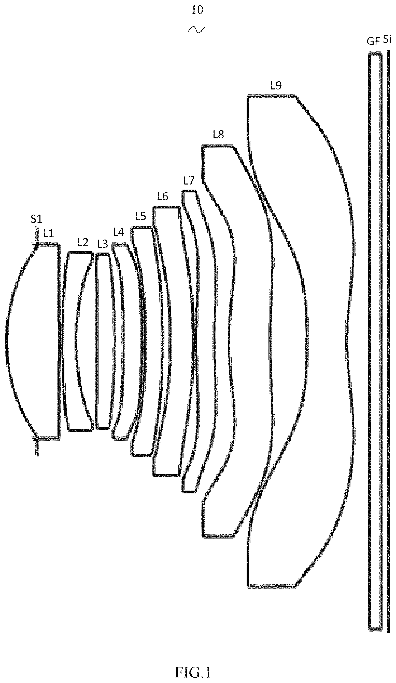
Referring to the drawings, the present disclosure provides a camera optical lens 10 . illustrates the camera optical lens 10 according to Embodiment 1 of the present disclosure. The camera optical lens 10 includes nine lenses. Specifically, the camera optical lens 10 successively includes, from an object side to an image side, an aperture S1, a first lens L1, a second lens L2, a third lens L3, a fourth lens L4, a fifth lens L5, a sixth lens L6, a seventh lens L7, an eighth lens L8, and a ninth lens L9. An optical element such as an optical filter GF may be provided between the ninth lens L9 and an image plane Si.
In this embodiment, the first lens L1 has a positive refractive power, the second lens L2 has a negative refractive power, the third lens L3 has a positive refractive power, the fourth lens L4 has a negative refractive power, the fifth lens L5 has a negative refractive power, the sixth lens L6 has a positive refractive power, the seventh lens L7 has a negative refractive power, the eighth lens L8 has a positive refractive power, and the ninth lens L9 has a negative refractive power. It should be understood that in other embodiments, the third lens L3, the eighth lens L8, and the ninth lens L9 may also have other refractive powers.
In this embodiment, the first lens L1 is made of a plastic material, the second lens L2 is made of a plastic material, the third lens L3 is made of a plastic material, the fourth lens L4 is made of a plastic material, the fifth lens L5 is made of a plastic material, the sixth lens L6 is made of a plastic material, the seventh lens L7 is made of a plastic material, the eighth lens L8 is made of a plastic material, and the ninth lens L9 is made of a plastic material. In other embodiments, each of the lenses may also be made of other material.
In the present embodiment, a focal length of the camera optical lens 10 is defined as f, and a focal length of the first lens L1 is defined as f1. The camera optical leans 10 satisfies a condition of 0.60≤f1/f≤1.80, which specifies a ratio of the focal length of the first lens to the focal length of the camera optical leans. When the condition is satisfied, spherical aberration and field curvature of the system can be effectively balanced.
An on-axis thickness of the sixth lens L6 is defined as d11, and an on-axis distance from an image side surface of the sixth lens L6 to an object side surface of the seventh lens L7 is defined as d12. The camera optical leans 10 satisfies a condition of 1.50≤d11/d12≤8.00, which specifies a ratio of the on-axis thickness of the sixth lens to an air gap between the sixth and seventh lenses. This condition facilitates reducing a total length of the optical system, thereby achieving an ultra-thin effect.
A central curvature radius of an object side surface of the sixth lens L6 is defined as R11, and a central curvature radius of the image side of the sixth lens L6 is defined as R12. The camera optical leans 10 satisfies a condition of (R11+R12)/(R11−R12)≤−4.50, which defines a shape of the sixth lens L6. This condition can alleviate the deflection of light passing through the lens, thereby effectively reducing aberration.
In the present embodiment, the first lens L1 includes an object side surface being convex at a paraxial position and an image side surface being convex at the paraxial position.
A central curvature radius of the object side surface of the first lens L1 is defined as R1, and a central curvature radius of the image side surface of the first lens L1 is defined as R2. The camera optical leans 10 satisfies a condition of −3.16≤(R1+R2)/(R1−R2)≤−0.42. This condition can reasonably control a shape of the first lens L1, such that the first lens L1 can effectively correct spherical aberration of the system. As an example, the camera optical leans 10 satisfies a condition of −1.97≤(R1+R2)/(R1−R2)≤−0.53.
An on-axis thickness of the first lens L1 is defined as d1, and a total optical length of the camera optical lens 10 is defined as TTL. The camera optical leans 10 satisfies a condition of 0.03≤d1/TTL≤0.21. This condition can facilitate achieving ultra-thin lenses. As an example, the camera optical leans 10 satisfies a condition of 0.05≤d1/TTL≤0.17.
In this embodiment, an object side surface of the second lens L2 is a convex surface at the paraxial position, and an image side surface of the second lens L2 is a concave surface at the paraxial position.
The focal length of the camera optical lens 10 is defined as f, and a focal length of the second lens L2 is defined as f2. The camera optical leans 10 satisfies a condition of −5.10≤f2/f≤−0.62. This condition can facilitate aberration correction of the optical system by controlling a negative refractive power of the second lens L2 within a reasonable range. As an example, the camera optical leans 10 satisfies a condition of −3.19≤f2/f≤−0.78.
A central curvature radius of the object side surface of the second lens L2 is defined as R3, and a central curvature radius of the image side surface of the second lens L2 is defined as R4. The camera optical leans 10 satisfies a condition of 0.68≤(R3+R4)/(R3−R4)≤7.37, which specifies a shape of the second lens L2. This condition can facilitate correcting the on-axis aberration with development of ultra-thin and wide-angle lenses. As an example, the camera optical leans 10 satisfies a condition of 1.09≤(R3+R4)/(R3−R4)≤5.90.
An on-axis thickness of the second lens L2 is defined as d3, and the total optical length of the camera optical lens 10 is defined as TTL. The camera optical leans 10 satisfies a condition of 0.02≤d3/TTL≤0.12. This condition can achieve ultra-thin lenses. As an example, the camera optical leans 10 satisfies a condition of 0.03≤d3/TTL≤0.09.
In this embodiment, an object side surface of the third lens L3 is a convex surface at the paraxial position, and an image side surface of the third lens L3 is a convex surface at the paraxial position.
The focal length of the camera optical lens 10 is defined as f, and a focal length of the third lens L3 is defined as f3. The camera optical leans 10 satisfies a condition of 1.02≤f3/f≤3.90. The system therefore achieves a better imaging quality and a lower sensitivity by reasonably distributing the refractive power. As an example, the camera optical leans 10 satisfies a condition of 1.64≤f3/f≤3.12.
A central curvature radius of the object side surface of the third lens L3 is defined as R5, and a central curvature radius of the image side surface of the third lens L3 is defined as R6. The camera optical leans 10 satisfies a condition of −2.75≤(R5+R6)/(R5−R6)≤0.73, which specifies a shape of the third lens. This condition can alleviate the deflection of light passing through the lens, thereby effectively reducing the aberration. As an example, the camera optical leans 10 satisfies a condition of −1.72≤(R5+R6)/(R5−R6)≤0.59.
The total optical length of the camera optical lens 10 is defined as TTL, and an on-axis thickness of the third lens L3 is defined as d5. The camera optical leans 10 satisfies a condition of 0.02≤d5/TTL≤0.09. This condition can facilitate achieving ultra-thin lenses. As an example, the camera optical leans 10 satisfies a condition of 0.04≤d5/TTL≤0.07.
In this embodiment, an object side surface of the fourth lens L4 is a concave surface at the paraxial position, and an image side surface of the fourth lens L4 is a convex surface at the paraxial position.
The focal length of the camera optical lens 10 is defined as f, and a focal length of the fourth lens L4 is defined as f4. The camera optical leans 10 satisfies a condition of −66.71≤f4/f≤14.76, which specifies a ratio of the focal length of the fourth lens to the focal length of the camera optical lens 10 . This condition can improve the performance of the optical system. As an example, the camera optical leans 10 satisfies a condition of −41.69≤f4/f≤11.81.
A central curvature radius of the object side surface of the fourth lens L4 is defined as R7, and a central curvature radius of the image side surface of the fourth lens L4 is defined as R8. The camera optical leans 10 satisfies a condition of −32.25≤(R7+R8)/(R7−R8)≤3.58, which specifies a shape of the fourth lens L4. This condition can facilitate aberration correction of an off-axis angle of view with development of ultra-thin and wide-angle lenses. As an example, the camera optical leans 10 satisfies a condition of −20.15≤(R7+R8)/(R7−R8)≤2.87.
The total optical length of the camera optical lens 10 is defined as TTL, and an on-axis thickness of the fourth lens L4 is defined as d7. The camera optical leans 10 satisfies a condition of 0.02≤d7/TTL≤0.08. This condition can facilitate achieving ultra-thin lenses. As an example, the camera optical leans 10 satisfies a condition of 0.04≤d7/TTL≤0.07.
In the present embodiment, the fifth lens L5 includes the object side surface being concave at the paraxial position and an image side surface being convex in the paraxial position.
The focal length of the camera optical lens 10 is defined as f, and a focal length of the fifth lens L5 is defined as f5. The camera optical leans 10 satisfies a condition of −62.10≤f5/f≤18.50. The fifth lens L5 is limited to effectively make a light angle of the camera optical lens 10 gentle and reduce the tolerance sensitivity. As an example, the camera optical leans 10 satisfies a condition of −38.81≤f5/f≤14.80.
A central curvature radius of the object side surface of the fifth lens L5 is defined as R9, and a central curvature radius of the image side surface of the fifth lens L5 is defined as R10. The camera optical leans 10 satisfies a condition of −9.02≤(R9+R10)/(R9−R10)≤0.50, which specifies a shape of the fifth lens L5. This condition can facilitate aberration correction of an off-axis angle of view with development of ultra-thin and wide-angle lenses. As an example, the camera optical leans 10 satisfies a condition of −5.64≤(R9+R10)/(R9−R10)≤0.40.
The total optical length of the camera optical lens 10 is defined as TTL, and an on-axis thickness of the fifth lens L5 is defined as d9. The camera optical leans 10 satisfies a condition of 0.02≤d9/TTL≤0.07. This condition can facilitate achieving ultra-thin lenses. As an example, the camera optical leans 10 satisfies a condition of 0.04≤d9/TTL≤0.06.
In this embodiment, an object side surface of the sixth lens L6 is a concave surface at the paraxial position, and the image side surface of the sixth lens L6 is a convex surface at the paraxial position.
The focal length of the camera optical lens 10 is defined as f, and a focal length of the sixth lens L6 is defined as f6. The camera optical leans 10 satisfies a condition of −29.24≤f6/f≤127.61. The system therefore achieves a better imaging quality and a lower sensitivity by reasonably distributing the refractive power. As an example, the camera optical leans 10 satisfies a condition of −18.27≤f6/f≤102.09.
The total optical length of the camera optical lens 10 is defined as TTL, and an on-axis thickness of the sixth lens L6 is defined as d11. The camera optical leans 10 satisfies a condition of 0.02≤d11/TTL≤0.09. This condition can facilitate achieving ultra-thin lenses. As an example, the camera optical leans 10 satisfies a condition of 0.03≤d11/TTL≤0.07.
In the present embodiment, the seventh lens L7 includes the object side surface being convex at the paraxial position and an image side surface being concave at the paraxial position.
The focal length of the camera optical lens 10 is defined as f, and a focal length of the seventh lens L7 is defined as P. The camera optical leans 10 satisfies a condition of −12.99≤f7/f≤38.81. The system therefore achieves a better imaging quality and a lower sensitivity by reasonably distributing the refractive power. As an example, the camera optical leans 10 satisfies a condition of −8.12≤f7/f≤31.05.
A central curvature radius of the object side surface of the seventh lens L7 is defined as R13, and a central curvature radius of the image side surface of the seventh lens L7 is defined as R14. The camera optical leans 10 satisfies a condition of −411.05≤(R13+R14)/(R13−R14)≤8.17, which defines a shape of the seventh lens L7. This condition can facilitate aberration correction of an off-axis angle of view with development of ultra-thin and wide-angle lenses. As an example, the camera optical leans 10 satisfies a condition of −256.91≤(R13+R14)/(R13−R14)≤6.53.
The total optical length of the camera optical lens 10 is defined as TTL, and an on-axis thickness of the seventh lens L7 is defined as d13. The camera optical leans 10 satisfies a condition of 0.02≤d13/TTL≤0.11. This condition can facilitate achieving ultra-thin lenses. As an example, the camera optical leans 10 satisfies a condition of 0.04≤d13/TTL≤0.09.
In this embodiment, an object side surface of the eighth lens L8 is a convex surface at the paraxial position, and an image side surface of the eighth lens L8 is a concave surface at the paraxial position.
The focal length of the camera optical lens 10 is defined as f, and a focal length of the eighth lens L8 is defined as f8. The camera optical leans 10 satisfies a condition of 0.68≤f8/f≤2.67. The system therefore achieves a better imaging quality and a lower sensitivity by reasonably distributing the refractive power. As an example, the camera optical leans 10 satisfies a condition of 1.08≤f8/f≤2.13.
A central curvature radius of the object side surface of the eighth lens L8 is defined as R15, and a central curvature radius of the image side surface of the eighth lens L8 is defined as R16. The camera optical leans 10 satisfies a condition of −4.80≤(R15+R16)/(R15−R16)≤−1.15, which specifies a shape of the eighth lens. This condition can facilitate aberration correction of an off-axis angle of view with development of ultra-thin and wide-angle lenses. As an example, the camera optical leans 10 satisfies a condition of −3.00≤(R15+R16)/(R15−R16)≤−1.44.
The total optical length of the camera optical lens 10 is defined as TTL, and an on-axis thickness of the eighth lens L8 is defined as d15. The camera optical leans 10 satisfies a condition of 0.04≤d15/TTL≤0.16. This condition can facilitate achieving ultra-thin lenses. As an example, the camera optical leans 10 satisfies a condition of 0.07≤d15/TTL≤0.13.
In this embodiment, an object side surface of the ninth lens L9 is a concave surface at the paraxial position, and an image side surface of the ninth lens L9 is a concave surface at the paraxial position. It should be understood that in other embodiments, the surface types of the object side surfaces and the image side surfaces of the first lens L1, the second lens L2, the third lens L3, the fourth lens L4, the fifth lens L5, the sixth lens L6, the seventh lens L7, the eighth lens L8 and the ninth lens L9 can also be configured to have other concave and convex distributions.
The focal length of the camera optical lens 10 is defined as f, and a focal length of the ninth lens L9 is defined as f9. The camera optical leans 10 satisfies a condition of −2.08≤f9/f≤−0.58. The system therefore achieves a better imaging quality and a lower sensitivity by reasonably distributing the refractive power. As an example, the camera optical leans 10 satisfies a condition of −1.30≤f9/f≤−0.72.
A central curvature radius of the object side surface of the ninth lens L9 is defined as R17, and a central curvature radius of the image side surface of the ninth lens L9 is defined as R18. The camera optical leans 10 satisfies a condition of 0.29≤(R17+R18)/(R17−R18)≤2.32, which specifies a shape of the ninth lens. This condition can facilitate aberration correction of an off-axis angle of view with development of ultra-thin and wide-angle lenses. As an example, the camera optical leans 10 satisfies a condition of 0.46≤(R17+R18)/(R17−R18)≤1.86.
The total optical length of the camera optical lens 10 is defined as TTL, and an on-axis thickness of the ninth lens L9 is defined as d17. The camera optical leans 10 satisfies a condition of 0.04≤d17/TTL≤0.16. This condition can facilitate achieving ultra-thin lenses. As an example, the camera optical leans 10 satisfies a condition of 0.07≤d17/TTL≤0.13.
In this embodiment, an image height of the camera optical lens 10 is defined as IH, and the total optical length of the camera optical lens 10 is defined as TTL. The camera optical leans 10 satisfies a condition of TTL/IH≤1.60, thereby achieving ultra-thin lenses.
In the present embodiment, a field of view angle (FOV) of the camera optical lens 10 is greater than or equal to 76.00°, thereby achieving a wide angle.
In the present embodiment, an F number FNO of the camera optical lens 10 is smaller than or equal to 1.90, thereby achieving a large aperture. The camera optical lens has good imaging performance.
When the above conditions are satisfied, the camera optical lens 10 can meet design requirements of a large aperture, a wide angle, and ultra-thinness while having good optical performance. According to the characteristics of the camera optical lens 10 , the camera optical lens 10 is particularly applicable to a mobile phone camera lens assembly and a WEB camera lens composed of high pixel CCD, CMOS, and other camera elements.
Examples of the camera optical lens 10 of the present disclosure are described below. Symbols described in each example will be described as follows. The focal length, on-axis distance, central curvature radius, on-axis thickness, inflexion point position, and arrest point position are all in units of mm.
TTL: total optical length (on-axis distance from the object side surface of the first lens L1 to the image plane) in mm.
F number (FNO): a ratio of an effective focal length of the camera optical lens to an entrance pupil diameter of the camera optical lens.
In some embodiments, at least one of the object side surface or the image side surface of each lens is provided with at least one of inflection points or arrest points to meet high-quality imaging requirements. The specific implementations can be referred to the following description.
Table 1 and Table 2 indicate design data of the camera optical lens 10 according to the Embodiment 1 of the present disclosure.
TABLE 1
R d
S1 ∞ d0 = −0.538 nd vd
R1 2.155 d1 = 0.918 nd1 1.5444 v1 55.82
R2 −9.731 d2 = 0.060
R3 18.214 d3 = 0.230 nd2 1.6400 v2 23.54
R4 2.792 d4 = 0.359
R5 30.573 d5 = 0.314 nd3 1.5444 v3 55.82
R6 −10.480 d6 = 0.153
R7 −11.855 d7 = 0.313 nd4 1.5444 v4 55.82
R8 −17.592 d8 = 0.061
R9 −11.824 d9 = 0.299 nd5 1.5444 v5 55.82
R10 −21.639 d10 = 0.140
R11 −6.723 d11 = 0.399 nd6 1.6400 v6 23.54
R12 −6.730 d12 = 0.050
R13 8.426 d13 = 0.315 nd7 1.5444 v7 55.82
R14 5.811 d14 = 0.251
R15 3.418 d15 = 0.717 nd8 1.5444 v8 55.82
R16 8.763 d16 = 0.638
R17 −12.286 d17 = 0.693 nd9 1.5346 v9 55.69
R18 3.303 d18 = 0.393
R19 ∞ d19 = 0.210 ndg 1.5168 vg 64.17
R20 ∞ d20 = 0.115
In the above table, meanings of the symbols will be described as follows.
S1: aperture;
R: curvature radius at center of an optical surface;
R1: central curvature radius of the object side surface of the first lens L1;
R2: central curvature radius of the image side surface of the first lens L1;
R3: central curvature radius of the object side surface of the second lens L2;
R4: central curvature radius of the image side surface of the second lens L2;
R5: central curvature radius of the object side surface of the third lens L3;
R6: central curvature radius of the image side surface of the third lens L3;
R7: central curvature radius of the object side surface of the fourth lens L4;
R8: central curvature radius of the image side surface of the fourth lens L4;
R9: central curvature radius of the object side surface of the fifth lens L5;
R10: central curvature radius of the image side surface of the fifth lens L5;
R11: central curvature radius of the object side surface of the sixth lens L6;
R12: central curvature radius of the image side surface of the sixth lens L6;
R13: central curvature radius of the object side surface of the seventh lens L7;
R14: central curvature radius of the image side surface of the seventh lens L7;
R15: central curvature radius of the object side surface of the eighth lens L8;
R16: central curvature radius of the image side surface of the eighth lens L8;
R17: central curvature radius of the object side surface of the ninth lens L9;
R18: central curvature radius of the image side surface of the ninth lens L9;
R19: central curvature radius of the object side surface of the optical filter GF;
R20: central curvature radius of the image side surface of the optical filter GF;
d: on-axis thickness of a lens and an on-axis distance between the lenses;
d0: on-axis distance from the aperture S1 to the object side surface of the first lens L1;
d1: on-axis thickness of the first lens L1;
d2: on-axis distance from the image side surface of the first lens L1 to the object side surface of the second lens L2;
d3: on-axis thickness of the second lens L2;
d4: on-axis distance from the image side surface of the second lens L2 to the object side surface of the third lens L3;
d5: on-axis thickness of the third lens L3;
d6: on-axis distance from the image side surface of the third lens L3 to the object side surface of the fourth lens L4;
d7: on-axis thickness of the fourth lens L4;
d8: on-axis distance from the image side surface of the fourth lens L4 to the object side surface of the fifth lens L5;
d9: on-axis thickness of the fifth lens L5;
d10: on-axis distance from the image side surface of the fifth lens L5 to the object side surface of the sixth lens L6;
d11: on-axis thickness of the sixth lens L6;
d12: on-axis distance from the image side surface of the sixth lens L6 to the object side surface of the seventh lens L7;
d13: on-axis thickness of the seventh lens L7;
d14: on-axis distance from the image side surface of the seventh lens L7 to the object side surface of the eighth lens L8;
d15: on-axis thickness of the eighth lens L8;
d16: on-axis distance from the image side surface of the eighth lens L8 to the object side surface of the ninth lens L9;
d17: on-axis thickness of the ninth lens L9;
d18: on-axis distance from the image side surface of the ninth lens L9 to the object side surface of the optical filter GF;
d19: on-axis thickness of the optical filter GF;
d20: on-axis distance from the image side surface of the optical filter GF to the image plane;
nd: refractive index of d-line;
nd1: refractive index of d-line of the first lens L1;
nd2: refractive index of d-line of the second lens L2;
nd3: refractive index of d-line of the third lens L3;
nd4: refractive index of d-line of the fourth lens L4;
nd5: refractive index of d-line of the fifth lens L5;
nd6: refractive index of d-line of the sixth lens L6;
nd7: refractive index of d-line of the seventh lens L7;
nd8: refractive index of d-line of the eighth lens L8;
nd9: refractive index of d-line of the ninth lens L9;
ndg: refractive index of d-line of the optical filter GF;
vd: abbe number;
v1: abbe number of the first lens L1;
v2: abbe number of the second lens L2;
v3: abbe number of the third lens L3;
v4: abbe number of the fourth lens L4;
v5: abbe number of the fifth lens L5;
v6: abbe number of the sixth lens L6;
v7: abbe number of the seventh lens L7;
v8: abbe number of the eighth lens L8;
v9: abbe number of the ninth lens L9; and
vg: abbe number of the optical filter GF.
Table 2 indicates aspherical surface data of each lens in the camera optical lens 10 according to the Embodiment 1 of the present disclosure.
TABLE 2
Conic
coefficient Aspheric surface coefficient
k A4 A6 A8 A10 A12
R1 6.1743E−02 5.9614E−03 −2.7519E−02 8.3553E−02 −1.1179E−01 5.8401E−02
R2 −5.4630E+02 4.0344E−02 3.0152E−01 −7.6341E−01 7.0730E−01 −1.7459E−01
R3 1.0829E+02 1.8526E−02 3.2257E−01 −7.8731E−01 7.8570E−01 −8.4108E−02
R4 −1.7907E+01 2.3327E−01 −1.3097E−01 4.0751E−01 −9.0958E−01 1.2437E+00
R5 −3.6531E+02 −1.6848E−01 3.8675E−02 3.5679E−01 −4.3347E−01 −1.3663E−01
R6 −4.4109E+01 −1.3253E−01 2.2983E−01 −1.8430E−01 7.7192E−03 −5.6922E−02
R7 −1.1500E+02 −5.9618E−02 −3.7052E−02 −8.7758E−02 −1.0563E−01 8.6677E−02
R8 −2.2024E+02 −9.3368E−02 −2.0373E−01 −9.0737E−02 1.3905E−01 4.8104E−02
R9 3.6193E+01 −1.0673E−01 −1.0831E−01 1.6373E−01 −8.6463E−02 −3.9702E−02
R10 1.3871E+02 −2.4420E−01 2.9595E−01 −1.7077E−01 −1.7060E−01 4.6769E−01
R11 7.2291E+00 −1.3811E−01 3.4865E−01 −6.0785E−01 6.0188E−01 −2.6119E−01
R12 −1.2702E+02 −2.2837E−01 3.5469E−01 −4.3951E−01 3.3711E−01 −1.2079E−01
R13 1.1903E+00 −1.5323E−01 7.6230E−02 −1.2603E−01 8.1794E−02 −2.5541E−02
R14 −1.6445E+02 −1.3863E−01 4.9541E−02 −1.0884E−01 8.7223E−02 −2.5961E−02
R15 −2.3141E+01 −1.0762E−01 4.3940E−02 −1.3323E−01 8.5540E−02 −2.4213E−02
R16 −5.8830E+01 −7.5142E−02 2.3301E−02 −3.6277E−02 1.6605E−02 −2.6818E−03
R17 −7.7429E+01 −4.6411E−01 2.7727E−01 −8.8901E−02 2.0311E−02 −3.3786E−03
R18 −1.9141E+00 −3.6760E−01 2.3897E−01 −1.1237E−01 3.4202E−02 −6.2699E−03
Conic
coefficient Aspheric surface coefficient
k A14 A16 A18 A20
R1 6.1743E−02 −1.4246E−02 5.1683E−03 1.2029E−02 −2.0417E−02
R2 −5.4630E+02 −3.1537E−02 −8.4162E−02 −2.1256E−02 6.3324E−02
R3 1.0829E+02 −5.9592E−02 −2.9297E−01 −7.4693E−02 2.6535E−01
R4 −1.7907E+01 6.1222E−01 −8.8559E−01 −1.8888E+00 1.9874E+00
R5 −3.6531E+02 5.4070E−01 7.3431E−01 9.0152E−02 −1.5357E+00
R6 −4.4109E+01 9.6869E−02 3.2124E−01 1.8075E−01 −9.2455E−01
R7 −1.1500E+02 −2.1290E−02 −4.0592E−01 −2.3851E−01 8.7629E−01
R8 −2.2024E+02 −1.3436E−01 −1.4038E−01 −2.7344E−03 2.9709E−01
R9 3.6193E+01 5.2903E−02 9.4836E−02 3.7021E−02 −1.1379E−01
R10 1.3871E+02 −3.0987E−01 6.5512E−02 −3.9550E−04 −5.2503E−03
R11 7.2291E+00 4.2365E−02 4.5134E−03 −2.3466E−03 −4.2446E−03
R12 −1.2702E+02 1.5985E−02 −9.9344E−04 −6.2548E−05 1.4562E−04
R13 1.1903E+00 4.0345E−03 −1.9573E−04 7.5883E−05 3.7082E−06
R14 −1.6445E+02 3.0700E−03 −2.2968E−04 −2.5369E−05 2.7666E−05
R15 −2.3141E+01 4.0106E−03 −2.0897E−04 −2.7330E−05 −7.9249E−06
R16 −5.8830E+01 1.0782E−04 2.2567E−06 −6.2721E−07 2.2884E−07
R17 −7.7429E+01 3.5074E−04 −1.6335E−05 −2.6224E−09 4.0818E−09
R18 −1.9141E+00 6.2067E−04 −2.5331E−05 −2.3024E−08 4.7584E−09
In Table 2, k is a conic coefficient, and A4, A6, A8, A10, A12, A14, A16, A18, and A20 are aspherical surface coefficients. y =( x 2 /R )/{1+[1−( k+ 1)( x 2 /R 2 )] 1/2 }+A 4 x 4 +A 6 x 6 +A 8 x 8 +A 10 x 10 +A 12 x 12 +A 14 x 14 +A 16 x 16 +A 18 x 18 +A 20 x 20 (1), where x is a vertical distance between a point on an aspherical curve and the optic axis, and y is an aspherical depth (a vertical distance between a point on an aspherical surface at a distance of x from the optic axis and a surface tangent to a vertex of the aspherical surface on the optic axis).
In the present embodiment, an aspherical surface of each lens surface uses the aspherical surface represented by the above formula (1). However, the present disclosure is not limited to the aspherical polynomial form represented by the formula (1).
Table 3 and Table 4 indicate design data of inflection points and arrest points of each lens in the camera optical lens 10 according to the Embodiment 1 of the present disclosure. P1R1 and P1R2 represent the object side surface and the image side surface of the first lens L1, respectively. P2R1 and P2R2 represent the object side surface and the image side surface of the second lens L2, respectively. P3R1 and P3R2 represent the object side surface and the image side surface of the third lens L3, respectively. P4R1 and P4R2 represent the object side surface and the image side surface of the fourth lens L4, respectively. P5R1 and P5R2 represent the object side surface and the image side surface of the fifth lens L5, respectively. P6R1 and P6R2 represent the object side surface and the image side surface of the sixth lens L6, respectively. P7R1 and P7R2 represent the object side surface and the image side surface of the seventh lens L7, respectively. P8R1 and P8R2 represent the object side surface and the image side surface of the eighth lens L8, respectively. P9R1 and P9R2 represent the object side surface and the image side surface of the ninth lens L9, respectively. Data in the “inflection point position” column refers to vertical distances from inflection points arranged on each lens surface to the optic axis of the camera optical lens 10 . Data in the “arrest point position” column refers to vertical distances from arrest points arranged on each lens surface to the optic axis of the camera optical lens 10 .
TABLE 3
Number of Inflexion Inflexion Inflexion
inflexion point point point
points position 1 position 2 position 3
P1R1 0 / / /
P1R2 2 0.435 1.195 /
P2R1 0 / / /
P2R2 0 / / /
P3R1 2 0.285 0.925 /
P3R2 0 / / /
P4R1 1 1.295 / /
P4R2 1 1.335 / /
P5R1 0 / / /
P5R2 2 1.255 1.465 /
P6R1 2 1.305 1.525 /
P6R2 2 1.385 1.835 /
P7R1 2 0.615 1.945 /
P7R2 2 0.455 1.905 /
P8R1 3 0.685 2.085 2.385
P8R2 1 0.675 / /
P9R1 2 1.825 3.405 /
P9R2 3 0.675 3.435 3.725
TABLE 4
Number of Arrest point Arrest point
arrest points position 1 position 2
P1R1 0 / /
P1R2 2 0.845 1.355
P2R1 0 / /
P2R2 0 / /
P3R1 2 0.505 1.095
P3R2 0 / /
P4R1 0 / /
P4R2 0 / /
P5R1 0 / /
P5R2 0 / /
P6R1 0 / /
P6R2 0 / /
P7R1 1 1.055 /
P7R2 1 0.875 /
P8R1 1 1.215 /
P8R2 1 1.175 /
P9R1 1 3.215 /
P9R2 1 1.415 /
and respectively illustrate schematic diagrams of longitudinal aberration and lateral color of light with wavelengths of 656 nm, 587 nm, 546 nm, 486 nm, and 436 nm after passing through the camera optical lens 10 in the Embodiment 1. illustrates a schematic diagram of field curvature and distortion of light with a wavelength of 546 nm after passing through the camera optical lens 10 in the Embodiment 1, in which the field curvature S is a field curvature in a sagittal direction, and T is a field curvature in a meridional direction.
Table 13 hereinafter indicates various values in Embodiments 1, 2, and 3 corresponding to parameters specified in the above conditions.
As shown in Table 13, the Embodiment 1 satisfies each of the above conditions.
In the present embodiment, the camera optical lens 10 has an entrance pupil diameter ENPD of 2.899 mm, an image height IH of full field of 4.350 mm, and the FOV (field of view) of 76.20° in a diagonal direction, such that the camera optical lens 10 meets design requirements for large aperture, wide angle and ultra-thinness while sufficiently correcting on-axis and off-axis chromatic aberration, thereby achieving excellent optical characteristics.
Embodiment 2
illustrates a schematic structural diagram of a camera optical lens 20 according to Embodiment 2 of the present disclosure. The Embodiment 2 is substantially the same as the Embodiment 1. The meanings of symbols in the Embodiment 2 are the same as those in the Embodiment 1. Differences therebetween will be described below.
In this embodiment, the image side surface of the first lens L1 is concave at the paraxial position, the image side surface of the third lens L3 is concave at the paraxial position, the object side surface of the ninth lens L9 is convex at the paraxial position, the sixth lens L6 has a negative refractive power, and the seventh lens L7 has a positive refractive power.
Table 5 and Table 6 indicate design data of the camera optical lens 20 according to the Embodiment 2 of the present disclosure.
TABLE 5
R d
S1 ∞ d0 = −0.449 nd vd
R1 2.493 d1 = 0.822 nd1 1.5444 v1 55.82
R2 13.714 d2 = 0.126
R3 4.171 d3 = 0.420 nd2 1.6400 v2 23.54
R4 2.315 d4 = 0.336
R5 5.178 d5 = 0.375 nd3 1.5444 v3 55.82
R6 32.908 d6 = 0.166
R7 −10.518 d7 = 0.378 nd4 1.5444 v4 55.82
R8 −11.909 d8 = 0.072
R9 −33.453 d9 = 0.333 nd5 1.5444 v5 55.82
R10 −52.508 d10 = 0.168
R11 −3.149 d11 = 0.237 nd6 1.6400 v6 23.54
R12 −3.453 d12 = 0.156
R13 3.886 d13 = 0.451 nd7 1.5444 v7 55.82
R14 3.924 d14 = 0.108
R15 3.738 d15 = 0.582 nd8 1.5444 v8 55.82
R16 14.064 d16 = 0.615
R17 10.405 d17 = 0.619 nd9 1.5346 v9 55.69
R18 2.244 d18 = 0.562
R19 ∞ d19 = 0.210 ndg 1.5168 vg 64.17
R20 ∞ d20 = 0.174
Table 6 indicates aspherical surface data of each lens in the camera optical lens 20 according to the Embodiment 2 of the present disclosure.
TABLE 6
Conic
coefficient Aspheric surface coefficient
k A4 A6 A8 A10 A12
R1 1.4662E−01 5.0826E−03 −2.0120E−02 8.1333E−02 −1.0756E−01 7.1885E−02
R2 −5.5072E+02 −1.7602E−01 5.6086E−01 −7.6525E−01 5.9456E−01 −2.1636E−01
R3 −4.2797E+01 −2.7123E−01 6.5822E−01 −7.5832E−01 4.9665E−01 −2.3952E−01
R4 −1.1822E+01 1.2037E−01 −1.8924E−01 6.6489E−01 −9.1211E−01 5.0622E−01
R5 2.5203E+00 −8.5531E−02 −7.0021E−02 1.8702E−01 −2.7954E−01 −3.5765E−02
R6 1.3258E+02 −2.7168E−02 1.2979E−01 −1.7453E−01 7.0631E−02 −2.0543E−02
R7 2.3770E+01 −6.6204E−02 1.7476E−01 3.7909E−02 −1.4051E−01 1.9193E−03
R8 −2.7739E+02 −7.4126E−02 −1.7674E−02 −4.1329E−02 1.8960E−03 4.0500E−03
R9 −9.8380E+02 −3.9693E−03 −1.5857E−01 −6.4822E−03 3.0781E−02 1.0388E−02
R10 6.6270E+02 −2.4837E−01 1.9154E−01 −1.5802E−01 −1.7359E−01 4.6648E−01
R11 3.5598E−01 −8.2829E−03 3.5365E−01 −6.2741E−01 5.9459E−01 −2.6349E−01
R12 −8.4273E+00 −1.5662E−01 3.6264E−01 −4.5240E−01 3.3215E−01 −1.1943E−01
R13 −1.9062E+01 −6.9519E−02 6.2116E−02 −1.3345E−01 8.1081E−02 −2.5186E−02
R14 −6.4800E+01 −4.5065E−02 6.3019E−02 −1.2792E−01 8.0872E−02 −2.5812E−02
R15 −4.2299E+01 −3.0548E−02 7.0838E−02 −1.3191E−01 8.0510E−02 −2.5751E−02
R16 −8.7677E+01 −1.0893E−02 2.5034E−02 −3.8908E−02 1.6362E−02 −2.7022E−03
R17 3.1357E+00 −4.9755E−01 2.7946E−01 −8.8799E−02 2.0276E−02 −3.3835E−03
R18 −3.4076E+00 −3.5288E−01 2.3827E−01 −1.1253E−01 3.4189E−02 −6.2702E−03
Conic
coefficient Aspheric surface coefficient
k A14 A16 A18 A20
R1 1.4662E−01 −8.2480E−03 −2.9583E−03 −3.8120E−04 −7.3002E−04
R2 −5.5072E+02 2.0502E−02 −4.4512E−03 −3.1361E−03 −2.0738E−04
R3 −4.2797E+01 1.0995E−01 −4.0665E−02 −3.5499E−03 −5.7747E−03
R4 −1.1822E+01 −4.4588E−02 −2.4071E−02 −6.8419E−03 −1.2385E−02
R5 2.5203E+00 1.9994E−01 −6.9895E−02 1.5512E−03 −4.0686E−03
R6 1.3258E+02 −3.6923E−02 4.3188E−02 1.7992E−03 −1.8216E−03
R7 2.3770E+01 8.6123E−02 −2.8867E−02 −9.4568E−04 −1.4232E−03
R8 −2.7739E+02 −1.0199E−03 2.2760E−03 1.4167E−03 1.2345E−03
R9 −9.8380E+02 3.1120E−03 −1.6529E−03 −6.9167E−04 −3.9047E−04
R10 6.6270E+02 −3.0584E−01 6.6615E−02 1.8291E−04 −8.6081E−05
R11 3.5598E−01 3.6507E−02 2.8929E−03 2.7102E−04 1.6405E−04
R12 −8.4273E+00 1.7450E−02 −3.6618E−04 −2.5835E−05 −1.4582E−05
R13 −1.9062E+01 4.0854E−03 −5.3313E−05 −6.2373E−06 −9.0103E−06
R14 −6.4800E+01 3.6437E−03 −6.4709E−05 −9.5376E−07 6.3079E−07
R15 −4.2299E+01 3.8020E−03 −1.2310E−04 8.6137E−08 −5.1050E−07
R16 −8.7677E+01 1.1989E−04 5.9376E−06 −1.1774E−08 −1.0097E−09
R17 3.1357E+00 3.5061E−04 −1.5927E−05 −1.7299E−09 −1.2660E−09
R18 −3.4076E+00 6.2128E−04 −2.5244E−05 −2.3204E−10 1.2287E−10
Table 7 and Table 8 indicate design data of inflection points and arrest points of each lens in the camera optical lens 20 according to the Embodiment 2 of the present disclosure.
TABLE 7
Number of Inflexion Inflexion Inflexion
inflexion point point point
points position 1 position 2 position 3
P1R1 0 / / /
P1R2 3 0.455 0.585 1.405
P2R1 1 1.165 / /
P2R2 1 1.415 / /
P3R1 1 0.895 / /
P3R2 2 1.035 1.455 /
P4R1 1 0.885 / /
P4R2 1 1.605 / /
P5R1 1 1.635 / /
P5R2 1 1.495 / /
P6R1 1 1.315 / /
P6R2 1 1.265 / /
P7R1 3 0.835 2.125 2.855
P7R2 2 0.735 2.315 /
P8R1 2 0.905 2.425 /
P8R2 1 1.105 / /
P9R1 3 0.295 1.885 3.435
P9R2 3 0.755 3.355 3.745
TABLE 8
Number of Arrest point Arrest point Arrest point
arrest points position 1 position 2 position 3
P1R1 0 / / /
P1R2 0 / / /
P2R1 1 1.435 / /
P2R2 0 / / /
P3R1 1 1.295 / /
P3R2 2 1.325 1.515 /
P4R1 1 1.375 / /
P4R2 0 / / /
P5R1 0 / / /
P5R2 0 / / /
P6R1 0 / / /
P6R2 1 1.875 / /
P7R1 3 1.395 2.395 3.005
P7R2 1 1.365 / /
P8R1 1 1.515 / /
P8R2 1 1.635 / /
P9R1 3 0.525 3.265 3.535
P9R2 1 1.685 / /
and respectively illustrate schematic diagrams of a longitudinal aberration and a lateral color of light with wavelengths of 656 nm, 587 nm, 546 nm, 486 nm, and 436 nm after passing through the camera optical lens 20 in the Embodiment 2. illustrates a schematic diagram of field curvature and distortion of light with a wavelength of 546 nm after passing through the camera optical lens 20 in the Embodiment 2.
As shown in Table 13, the Embodiment 2 satisfies the above conditions.
In this embodiment, the camera optical lens 20 has an entrance pupil diameter ENPD of 2.876 mm, an image height IH of full field of 4.350 mm, and the FOV (field of view) of 76.40° in a diagonal direction, such that the camera optical lens 20 meets design requirements for large aperture, wide angle and ultra-thinness while sufficiently correcting on-axis and off-axis chromatic aberration, thereby achieving excellent optical characteristics.
Embodiment 3
is a schematic structural diagram of a camera optical lens 30 according to Embodiment 3 of the present disclosure. The Embodiment 3 is substantially the same as the Embodiment 1. The meanings of symbols in the Embodiment 3 are the same as those in the Embodiment 1. Differences therebetween will be described below.
In this embodiment, the image side surface of the first lens L1 is concave at the paraxial position, the image side surface of the third lens L3 is concave at the paraxial position, the object side surface of the fifth lens L5 is convex at the paraxial position, the object side surface of the ninth lens L9 is convex at the paraxial position, the fourth lens L4 has a positive refractive power, the fifth lens L5 has a positive refractive power, the sixth lens L6 has a negative refractive power, and the seventh lens L7 has a positive refractive power.
Table 9 and Table 10 indicate design data of the camera optical lens 30 according to the Embodiment 3 of the present disclosure.
TABLE 9
R d
S1 ∞ d0 = −0.250 nd vd
R1 3.837 d1 = 0.440 nd1 1.5444 v1 55.82
R2 17.092 d2 = 0.118
R3 3.456 d3 = 0.534 nd2 1.6400 v2 23.54
R4 2.287 d4 = 0.141
R5 4.871 d5 = 0.416 nd3 1.5444 v3 55.82
R6 33.662 d6 = 0.352
R7 −38.935 d7 = 0.357 nd4 1.5444 v4 55.82
R8 −15.953 d8 = 0.123
R9 100.837 d9 = 0.330 nd5 1.5444 v5 55.82
R10 −50.545 d10 = 0.106
R11 −4.098 d11 = 0.253 nd6 1.6400 v6 23.54
R12 −6.214 d12 = 0.060
R13 2.924 d13 = 0.517 nd7 1.5444 v7 55.82
R14 3.154 d14 = 0.314
R15 2.328 d15 = 0.645 nd8 1.5444 v8 55.82
R16 5.654 d16 = 0.769
R17 11.543 d17 = 0.615 nd9 1.5346 v9 55.69
R18 2.206 d18 = 0.453
R19 ∞ d19 = 0.210 ndg 1.5168 vg 64.17
R20 ∞ d20 = 0.160
Table 10 indicates aspherical surface data of each lens in the camera optical lens 30 according to the Embodiment 3 of the present disclosure.
TABLE 10
Conic
coefficient Aspheric surface coefficient
k A4 A6 A8 A10 A12
R1 6.4491E−01 2.1347E−02 −2.5776E−02 1.9259E−01 −9.8518E−02 9.6068E−03
R2 −1.0000E+03 −1.6500E−01 6.8444E−01 −8.0375E−01 5.9573E−01 −2.0896E−01
R3 −2.1003E+01 −2.2142E−01 6.1495E−01 −8.5499E−01 5.3946E−01 −2.5937E−01
R4 −9.0505E+00 7.9966E−02 −2.2493E−01 6.2555E−01 −9.8285E−01 5.9722E−01
R5 5.7262E+00 −9.8571E−02 5.6246E−02 1.0354E−01 −3.0527E−01 6.1615E−02
R6 3.7553E+02 −4.1082E−02 9.5982E−02 −1.8906E−01 9.0554E−02 −2.2913E−02
R7 5.3805E+02 −2.4505E−01 1.3190E−01 −4.1354E−02 −1.4376E−01 −3.1469E−02
R8 5.8157E+01 −2.1165E−01 8.3285E−04 −1.4570E−02 1.7868E−02 −1.2242E−02
R9 −9.7532E+02 3.3332E−03 −2.0258E−01 1.0490E−02 3.0140E−02 −1.3187E−03
R10 5.9662E+02 −2.8721E−01 2.3659E−01 −1.9545E−01 −2.0968E−01 4.8291E−01
R11 −6.6104E−01 2.5794E−02 3.7701E−01 −6.8375E−01 6.1702E−01 −2.8275E−01
R12 −1.0756E+02 −1.4342E−01 3.8565E−01 −4.7959E−01 3.5262E−01 −1.2723E−01
R13 −6.3384E+00 −8.7998E−02 7.5677E−02 −1.4046E−01 8.6120E−02 −2.6303E−02
R14 −3.1809E+01 −1.0265E−02 4.8932E−02 −1.3150E−01 8.6943E−02 −2.7494E−02
R15 −8.9187E+00 −8.8894E−02 9.3722E−02 −1.4364E−01 8.4520E−02 −2.7238E−02
R16 −5.6095E+00 −4.9880E−02 2.5187E−02 −4.0147E−02 1.7489E−02 −2.8711E−03
R17 5.3242E+00 −5.3203E−01 2.9681E−01 −9.4190E−02 2.1518E−02 −3.5847E−03
R18 −3.5431E+00 −3.4567E−01 2.4588E−01 −1.1927E−01 3.6362E−02 −6.6448E−03
Conic
coefficient Aspheric surface coefficient
k A14 A16 A18 A20
R1 6.4491E−01 −2.2093E−02 1.7509E−01 1.4810E−01 −1.7389E−01
R2 −1.0000E+03 1.3638E−01 1.5009E−01 −5.4509E−02 −1.5071E−02
R3 −2.1003E+01 9.2210E−02 5.5092E−02 1.6129E−01 −3.2057E−01
R4 −9.0505E+00 6.6693E−02 −8.5082E−02 −1.4269E−01 9.1054E−02
R5 5.7262E+00 2.9669E−01 −1.1629E−01 −1.1564E−01 7.3357E−02
R6 3.7553E+02 −6.0246E−02 2.5352E−02 6.8543E−03 6.1953E−02
R7 5.3805E+02 5.6780E−02 −2.9617E−02 3.5388E−02 1.4487E−02
R8 5.8157E+01 −2.1056E−02 −8.0819E−03 1.6652E−03 2.1776E−03
R9 −9.7532E+02 −9.5990E−03 −1.4107E−02 −4.3213E−03 8.7342E−03
R10 5.9662E+02 −3.2706E−01 7.3032E−02 5.2704E−03 6.4313E−03
R11 −6.6104E−01 4.3085E−02 8.5371E−03 2.0433E−03 −3.1986E−03
R12 −1.0756E+02 1.7919E−02 −6.4631E−04 −4.4972E−05 2.9717E−05
R13 −6.3384E+00 4.5287E−03 −1.4569E−05 −1.6638E−05 −3.4451E−05
R14 −3.1809E+01 3.7216E−03 −1.0355E−04 −1.4512E−06 7.1421E−06
R15 −8.9187E+00 4.1506E−03 −9.8358E−05 3.1439E−07 −4.2338E−06
R16 −5.6095E+00 1.2338E−04 5.7958E−06 3.7392E−10 3.9683E−08
R17 5.3242E+00 3.7292E−04 −1.6813E−05 −2.6708E−08 −2.2919E−08
R18 −3.5431E+00 6.5901E−04 −2.6915E−05 −1.7694E−08 −7.4977E−10
Table 11 and Table 12 indicate design data of inflection points and arrest points of each lens in the camera optical lens 30 according to the Embodiment 3 of the present disclosure.
TABLE 11
Number of Inflexion Inflexion Inflexion
inflexion point point point
points position 1 position 2 position 3
P1R1 0 / / /
P1R2 0 / / /
P2R1 1 0.995 / /
P2R2 0 / / /
P3R1 0 / / /
P3R2 2 0.865 1.395 /
P4R1 1 1.535 / /
P4R2 0 / / /
P5R1 1 0.415 / /
P5R2 1 1.615 / /
P6R1 2 1.135 1.665 /
P6R2 2 0.955 1.985 /
P7R1 2 1.025 2.125 /
P7R2 2 0.985 2.425 /
P8R1 2 0.975 2.545 /
P8R2 2 1.175 3.245 /
P9R1 3 0.305 2.005 3.215
P9R2 3 0.845 3.585 3.735
TABLE 12
Number of Arrest point Arrest point
arrest points position 1 position 2
P1R1 0 / /
P1R2 0 / /
P2R1 0 / /
P2R2 0 / /
P3R1 0 / /
P3R2 2 1.165 1.485
P4R1 0 / /
P4R2 0 / /
P5R1 1 0.615 /
P5R2 0 / /
P6R1 0 / /
P6R2 1 1.595 /
P7R1 1 1.725 /
P7R2 1 1.665 /
P8R1 1 1.715 /
P8R2 1 1.885 /
P9R1 1 0.535 /
P9R2 1 2.005 /
and respectively illustrate schematic diagrams of a longitudinal aberration and a lateral color of light with wavelengths of 656 nm, 587 nm, 546 nm, 486 nm, and 436 nm after passing through the camera optical lens 30 in the Embodiment 3. illustrates a schematic diagram of field curvature and distortion of light with a wavelength of 546 nm after passing through the camera optical lens 30 in the Embodiment 3.
Table 13 below lists values corresponding to the conditions in the present embodiment according to the above conditions. Apparently, the camera optical lens in the present embodiment satisfies the above conditions.
In this embodiment, the camera optical lens 30 has an entrance pupil diameter ENPD of 2.630 mm, an image height IH of full field of 4.350 mm, and the FOV (field of view) of 81.25° in a diagonal direction, such that the camera optical lens 30 meets design requirements for large aperture, wide angle and ultra-thinness while sufficiently correcting on-axis and off-axis chromatic aberration, thereby achieving excellent optical characteristics.
TABLE 13
Parameter and
Condition Embodiment 1 Embodiment 2 Embodiment 3
f1/f 0.60 0.99 1.79
d11/d12 7.98 1.52 4.22
f 5.507 5.464 4.996
f1 3.318 5.431 8.946
f2 −5.130 −8.832 −12.741
f3 14.314 11.185 10.363
f4 −67.805 −182.254 49.165
f5 −48.195 −169.662 61.629
f6 468.513 −79.871 −19.538
f7 −35.773 141.365 40.888
f8 9.787 9.130 6.773
f9 −4.774 −5.473 −5.198
FNO 1.90 1.90 1.90
TTL 6.628 6.910 6.913
IH 4.350 4.350 4.350
FOV 76.20° 76.40° 81.25°
The above are only the embodiments of the present disclosure. It should be understood that those skilled in the art can make improvements without departing from the inventive concept of the present disclosure, and these improvements shall all belong to the scope of the present disclosure.
Figures (9)
Citations
This patent cites (1)
- US20200241243