Abstract
A lens assembly includes a first lens, a second lens, and a third lens. The first lens is with negative refractive power and includes a concave surface facing an image side. The second lens is with positive refractive power and includes a convex surface facing the image side. The third lens is with positive refractive power and includes a convex surface facing an object side. The first lens, the second lens, and the third lens are arranged in order from the object side to the image side along an optical axis. The lens assembly satisfies the following condition: 3.5≤R 21 /≤8; wherein R 21 is a radius of curvature of an object side surface of the second lens and f is an effective focal length of the lens assembly.
Claims (17)
1. A lens assembly comprising: a first lens which is with negative refractive power and comprises a concave surface facing an image side; a second lens which is with positive refractive power and comprises a convex surface facing the image side; and a third lens which is with positive refractive power and comprises a convex surface facing an object side; wherein the first lens, the second lens, and the third lens are arranged in order from the object side to the image side along an optical axis; wherein the lens assembly satisfies the following conditions: 3.5≤ R 21 /f≤ 8; 14≤ R 11 /f≤ 20.5; wherein R 11 is a radius of curvature of an object side surface of the first lens, R 21 is a radius of curvature of an object side surface of the second lens and f is an effective focal length of the lens assembly.
8. A lens assembly comprising: a first lens which is with negative refractive power and comprises a concave surface facing an image side; a second lens which is with positive refractive power and comprises a convex surface facing the image side; and a third lens which is with positive refractive power and comprises a convex surface facing an object side; wherein the first lens, the second lens, and the third lens are arranged in order from the object side to the image side along an optical axis; wherein the lens assembly satisfies the following condition: 14≤ R 11 /f≤ 20.5; 2.4< R 11 /R 21 ≤3.9; wherein R 11 is a radius of curvature of an object side surface of the first lens, R 21 is a radius of curvature of an object side surface of the second lens and f is an effective focal length of the lens assembly.
14. A lens assembly comprising: a first lens which is with negative refractive power and comprises a concave surface facing an image side; a second lens which is with positive refractive power and comprises a convex surface facing the image side; and a third lens which is with positive refractive power and comprises a convex surface facing an object side; wherein the first lens, the second lens, and the third lens are arranged in order from the object side to the image side along an optical axis; wherein the lens assembly satisfies the following condition: 8.4 mm≤ R 11 /( f 2 /f 3 )≤14.5 mm; 14≤R 11 /f≤20.5; wherein R 11 is a radius of curvature of an object side surface of the first lens, f is an effective focal length of the lens assembly, f 2 is an effective focal length of the second lens, and f 3 is an effective focal length of the third lens.
Show 14 dependent claims
2. The lens assembly as claimed in claim 1 , wherein: the first lens further comprises a convex surface facing the object side; the second lens further comprises another convex surface facing the object side; and the third lens further comprises another convex surface facing the image side.
3. The lens assembly as claimed in claim 2 , wherein at least one of the first lens, the second lens, and the third lens is an aspherical lens.
4. The lens assembly as claimed in claim 1 , wherein the lens assembly satisfies the following condition: 2.4≤ R 11 /R 21 ≤3.9; wherein R 11 is the radius of curvature of the object side surface of the first lens and R 21 is the radius of curvature of the object side surface of the second lens.
5. The lens assembly as claimed in claim 1 , wherein the lens assembly satisfies the following condition: 8.4 mm≤ R 11 /( f 2 /f 3 )≤14.5 mm; wherein R 11 is a radius of curvature of an object side surface of the first lens, f 2 is an effective focal length of the second lens, and f 3 is an effective focal length of the third lens.
6. The lens assembly as claimed in claim 1 , wherein the lens assembly satisfies the following condition: 24degrees/ mm ≤HFOV/ f 3 ≤35degrees/ mm; wherein HFOV is a half field of view of the lens assembly and f 3 is an effective focal length of the third lens.
7. The lens assembly as claimed in claim 1 , further comprising a stop disposed between the second lens and the third lens.
9. The lens assembly as claimed in claim 8 , wherein: the first lens further comprises a convex surface facing the object side; the second lens further comprises another convex surface facing the object side; and the third lens further comprises another convex surface facing the image side.
10. The lens assembly as claimed in claim 9 , wherein at least one of the first lens, the second lens, and the third lens is an aspherical lens.
11. The lens assembly as claimed in claim 8 , wherein the lens assembly satisfies the following condition: 8.4 mm≤ R 11 /( f 2 /f 3 )≤14.5 mm; wherein R 11 is the radius of curvature of the object side surface of the first lens, f 2 is an effective focal length of the second lens, and f 3 is an effective focal length of the third lens.
12. The lens assembly as claimed in claim 8 , wherein the lens assembly satisfies the following condition: 24 degrees/ mm ≤ HFOV/ f 3 ≤35 degrees/ mm; wherein HFOV is a half field of view of the lens assembly and f 3 is an effective focal length of the third lens.
13. The lens assembly as claimed in claim 8 , further comprising a stop disposed between the second lens and the third lens.
15. The lens assembly as claimed in claim 14 , wherein: the first lens further comprises a convex surface facing the object side; the second lens further comprises another convex surface facing the object side; and the third lens further comprises another convex surface facing the image side.
16. The lens assembly as claimed in claim 14 , wherein the lens assembly satisfies the following condition: 24 degrees/ mm ≤HFOV/ f 3 ≤35 degrees/ mm; wherein HFOV is a half field of view of the lens assembly and f 3 is an effective focal length of the third lens.
17. The lens assembly as claimed in claim 14 , further comprising a stop disposed between the second lens and the third lens.
Full Description
Show full text →
BACKGROUND OF THE INVENTION
Field of the Invention
The invention relates to a lens assembly.
Description of the Related Art
Today's lens assemblies have the characteristics of miniaturization, larger field of view, and larger stop. However, due to the large incident angle, the brightness of the peripheral image is insufficient which is not conducive to night environment applications. Therefore, the lens assembly needs a new structure which can not only have high peripheral brightness but also achieve miniaturization, large field of view and large stop, to meet the requirements of night environment application.
BRIEF SUMMARY OF THE INVENTION
The invention provides a lens assembly to solve the above problems. The lens assembly of the invention is provided with characteristics of a decreased total lens length, an increased field of view, a decreased f-number, an increased brightness of periphery image, and still has a good optical performance.
The lens assembly in accordance with an exemplary embodiment of the invention includes a first lens, a second lens, and a third lens. The first lens is with negative refractive power and includes a concave surface facing an image side. The second lens is with positive refractive power and includes a convex surface facing the image side. The third lens is with positive refractive power and includes a convex surface facing an object side. The first lens, the second lens, and the third lens are arranged in order from the object side to the image side along an optical axis. The lens assembly satisfies the following condition: 3.5≤R 21 /f≤8; wherein R 21 is a radius of curvature of an object side surface of the second lens and f is an effective focal length of the lens assembly.
In another exemplary embodiment, the first lens further includes a convex surface facing the object side, the second lens further includes another convex surface facing the object side, and the third lens further includes another convex surface facing the image side.
In yet another exemplary embodiment, at least one of the first lens, the second lens, and the third lens is an aspherical lens.
In another exemplary embodiment, the lens assembly satisfies the following condition: 14≤R 11 /f≤20.5; wherein R 11 is a radius of curvature of an object side surface of the first lens and f is the effective focal length of the lens assembly.
In yet another exemplary embodiment, the lens assembly satisfies the following condition: 2.4≤R 11 /R 21 ≤3.9; wherein R 11 is a radius of curvature of the object side surface of the first lens and R 21 is the radius of curvature of the object side surface of the second lens.
In another exemplary embodiment, the lens assembly satisfies the following condition: 8.4 mm≤R 11 /(f 2 /f 3 )≤14.5 mm; wherein R 11 is a radius of curvature of an object side surface of the first lens, f 2 is an effective focal length of the second lens, and f 3 is an effective focal length of the third lens.
In yet another exemplary embodiment, the lens assembly satisfies the following condition: 24 degrees/mm≤HFOV/f 3 ≤35 degrees/min; wherein HFOV is a half field of view of the lens assembly and f 3 is an effective focal length of the third lens.
In another exemplary embodiment, the lens assembly further includes a stop disposed between the second lens and the third lens.
The lens assembly in accordance with another exemplary embodiment of the invention includes a first lens, a second lens, and a third lens. The first lens is with negative refractive power and includes a concave surface facing an image side. The second lens is with positive refractive power and includes a convex surface facing the image side. The third lens is with positive refractive power and includes a convex surface facing an object side. The first lens, the second lens, and the third lens are arranged in order from the object side to the image side along an optical axis. The lens assembly satisfies the following condition: 14≤R 11 /f≤20.5; wherein R 11 is a radius of curvature of an object side surface of the first lens and f is an effective focal length of the lens assembly.
In another exemplary embodiment, the first lens further includes a convex surface facing the object side, the second lens further includes another convex surface facing the object side, and the third lens further includes another convex surface facing the image side.
In yet another exemplary embodiment, at least one of the first lens, the second lens, and the third lens is an aspherical lens.
In another exemplary embodiment, the lens assembly satisfies the following condition: 2.4≤R 11 /R 21 ≤3.9; wherein R 11 is the radius of curvature of the object side surface of the first lens and R 21 is a radius of curvature of an object side surface of the second lens.
In yet another exemplary embodiment, the lens assembly satisfies the following condition: 8.4 mm≤R 11 /(f 2 /f 3 ≤14.5 mm; wherein R 11 is the radius of curvature of the object side surface of the first lens, f 2 is an effective focal length of the second lens, and f 3 is an effective focal length of the third lens.
In another exemplary embodiment, the lens assembly satisfies the following condition: 24 degrees/mm≤HFOV/f 3 ≤35 degrees/mm wherein HFOV is a half field of view of the lens assembly and f 3 is an effective focal length of the third lens.
In yet another exemplary embodiment, the lens assembly further includes a stop disposed between the second lens and the third lens.
The lens assembly in accordance with yet another exemplary embodiment of the invention includes a first lens, a second lens, and a third lens. The first lens is with negative refractive power and includes a concave surface facing an image side. The second lens is with positive refractive power and includes a convex surface facing the image side. The third lens is with positive refractive power and includes a convex surface facing an object side. The first lens, the second lens, and the third lens are arranged in order from the object side to the image side along an optical axis. The lens assembly satisfies the following condition: 8.4 mm≤R 11 /(f 2 /f 3 )≤14.5 mm; wherein R 11 is a radius of curvature of an object side surface of the first lens, f 2 is an effective focal length of the second lens, and f 3 is an effective focal length of the third lens.
In another exemplary embodiment, the first lens further includes a convex surface facing the object side, the second lens further includes another convex surface facing the object side, and the third lens further includes another convex surface facing the image side.
In yet another exemplary embodiment, the lens assembly satisfies the following condition: 2.4≤R 11 /R 21 ≤3.9; wherein R 11 is the radius of curvature of the object side surface of the first lens and R 21 is a radius of curvature of an object side surface of the second lens.
In another exemplary embodiment, the lens assembly satisfies the following condition: 24 degrees/mm≤HFOV/f 3 ≤35 degrees/mm, wherein HFOV is a half field of view of the lens assembly and f 3 is an effective focal length of the third lens.
In yet another exemplary embodiment, the lens assembly further includes a stop disposed between the second lens and the third lens.
A detailed description is given in the following embodiments with reference to the accompanying drawings.
BRIEF DESCRIPTION OF THE DRAWINGS
The invention can be more fully understood by reading the subsequent detailed description and examples with references made to the accompanying drawings, wherein:
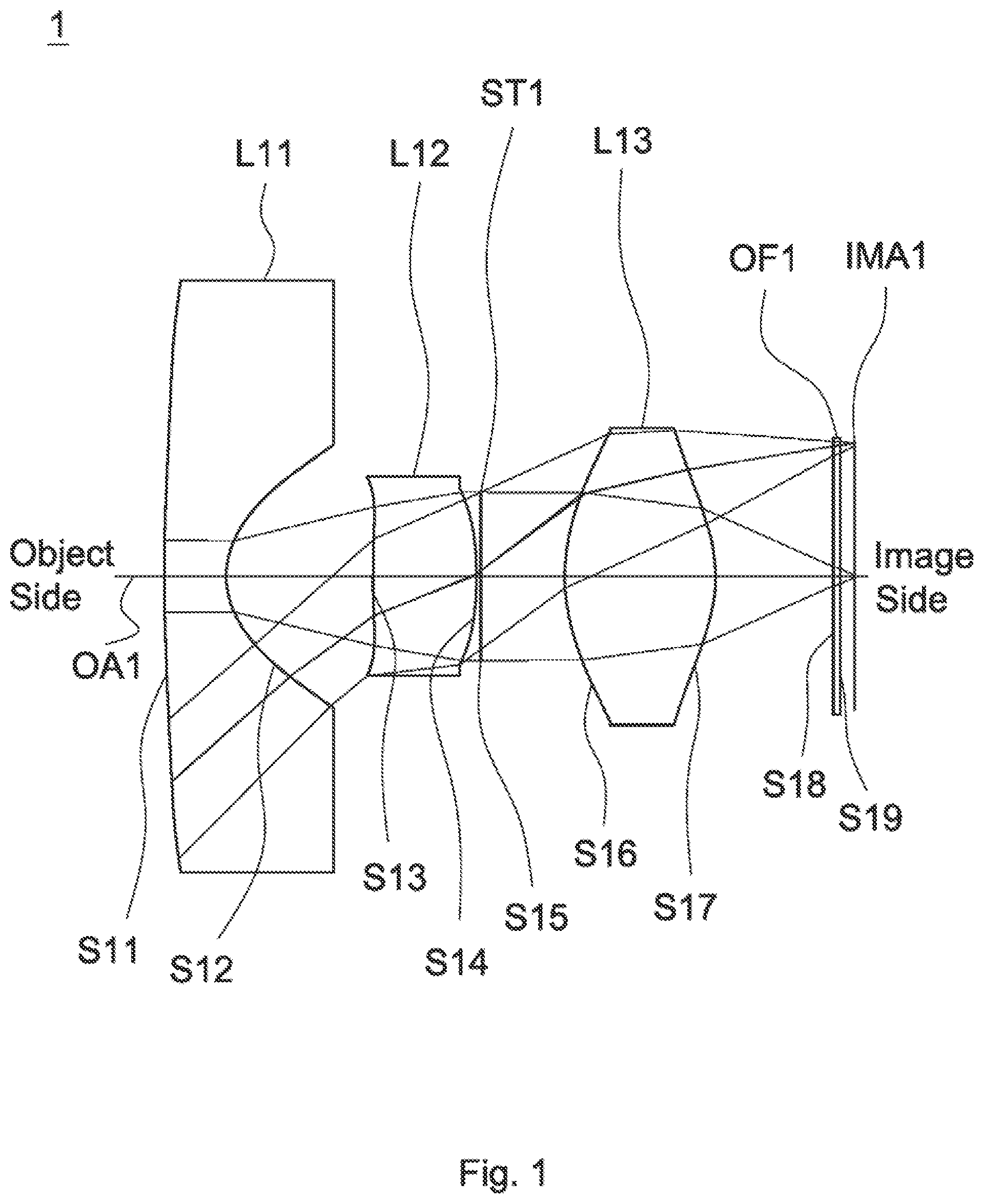
is a lens layout and optical path diagram of a lens assembly in accordance with a first embodiment of the invention;
A depicts a longitudinal aberration diagram of the lens assembly in accordance with the first embodiment of the invention;
B is a field curvature diagram of the lens assembly in accordance with the first embodiment of the invention;
C is a distortion diagram of the lens assembly in accordance with the first embodiment of the invention;
is a lens layout and optical path diagram of a lens assembly in accordance with a second embodiment of the invention;
A depicts a longitudinal aberration diagram of the lens assembly in accordance with the second embodiment of the invention;
B is a field curvature diagram of the lens assembly in accordance with the second embodiment of the invention;
C is a distortion diagram of the lens assembly in accordance with the second embodiment of the invention;
is a lens layout and optical path diagram of a lens assembly in accordance with a third embodiment of the invention;
A depicts a longitudinal aberration diagram of the lens assembly in accordance with the third embodiment of the invention;
B is a field curvature diagram of the lens assembly in accordance with the third embodiment of the invention; and
C is a distortion diagram of the lens assembly in accordance with the third embodiment of the invention.
DETAILED DESCRIPTION OF THE INVENTION
The following description is made for the purpose of illustrating the general principles of the invention and should not be taken in a limiting sense. The scope of the invention is best determined by reference to the appended claims.
The present invention provides a lens assembly including a first lens, a second lens, and a third lens. The first lens which is with negative refractive power and includes a concave surface facing an image side. The second lens which is with positive refractive power and includes a convex surface facing the image side. The third lens which is with positive refractive power and includes a convex surface facing an object side. The first lens, the second lens, and the third lens are arranged in order from the object side to the image side along an optical axis. The lens assembly satisfies the following condition: 3.5≤R 21 /f≤8; wherein R 21 is a radius of curvature of an object side surface of the second lens and f is an effective focal length of the lens assembly.
The present invention provides another lens assembly including a first lens, a second lens, and a third lens. The first lens which is with negative refractive power and includes a concave surface facing an image side. The second lens which is with positive refractive power and includes a convex surface facing the image side. The third lens which is with positive refractive power and includes a convex surface facing an object side. The first lens, the second lens, and the third lens are arranged in order from the object side to the image side along an optical axis, The lens assembly satisfies the following condition: 14≤R 11 /f≤20.5; wherein R 11 is a radius of curvature of an object side surface of the first lens and f is an effective focal length of the lens assembly.
The present invention provides yet another lens assembly including a first lens, a second lens, and a third lens. The first lens which is with negative refractive power and includes a concave surface facing an image side. The second lens which is with positive refractive power and includes a convex surface facing the image side. The third lens which is with positive refractive power and includes a convex surface facing an object side. The first lens, the second lens, and the third lens are arranged in order from the object side to the image side along an optical axis. The lens assembly satisfies the following condition: 8.4 mm≤R 11 /(f 2 /f 3 )≤14.5 mm; wherein R 11 is a radius of curvature of an object side surface of the first lens, f 2 is an effective focal length of the second lens, and f 3 is an effective focal length of the third lens.
Referring to Table 1, Table 2, Table 4, Table 5, Table 7, and Table 8, wherein Table 1, Table 4, and Table 7 show optical specification in accordance with a first, second, and third embodiments of the invention respectively and Table 2, Table 5, and Table 8 show aspheric coefficient of each aspheric lens in Table 1, Table 4, and Table 7 respectively.
, , and are lens layout and optical path diagrams of the lens assemblies in accordance with the first, second, and third embodiments of the invention respectively.
The first lenses L 11 , L 21 , L 31 are meniscus lenses with negative refractive power, wherein the object side surfaces S 11 , S 21 , S 31 are convex surfaces which can effectively increase the maximum half field of view, the image side surfaces S 12 , S 22 , S 32 are concave surfaces, and the object side surfaces S 11 , S 21 , S 31 and the image side surfaces S 12 , S 22 , S 32 are aspheric surfaces.
The second lenses L 12 , L 22 , L 32 are biconvex lenses with positive refractive power, wherein the object side surfaces S 13 , S 23 , S 33 are convex surfaces which can further decrease the light angle to avoid too large chief ray angle, the image side surfaces S 14 , S 24 , S 34 are convex surfaces, and the object side surfaces S 13 , S 23 , S 33 and the image side surfaces S 14 , S 24 , S 34 are aspheric surfaces.
The third lenses L 13 , L 23 , L 33 are biconvex lenses with positive refractive power, wherein the object side surfaces S 16 , S 26 , S 36 are convex surfaces which can decrease the angle of the light of the maximum half field of view incident on the image plane, and the object side surfaces S 16 , S 26 , S 36 and the image side surfaces S 17 , S 27 , S 37 are aspheric surfaces.
In addition, the wide-angle lens assemblies 1 , 2 , 3 satisfy at least one of the following conditions: 3.5≤R 2 /f≤8; (1) 24 degrees/mm≤HFOV/f 3 ≤35 degrees/mm; (2) 14≤R 11 /f≤20.5; (3) 8.4 mm≤R 11 /(f 2 /f 3 )≤14.5 mm; (4) 2.4≤R 11 /R 21 ≤3.9 (5) wherein is a radius of curvature of the objet side surfaces S 11 , S 21 , S 31 of the first lenses L 11 , L 21 , L 31 for the first to third embodiments, R 21 is a radius of curvature of the objet side surfaces S 13 , S 23 , S 33 of the second lenses L 12 , L 22 , L 32 for the first to third embodiments, f is an effective focal length of the lens assemblies 1 , 2 , 3 for the first to third embodiments, f 2 is an effective focal length of the second lenses L 12 , L 22 , L 32 for the first to third embodiments, f 3 is an effective focal length of the third lenses L 13 , L 23 , L 33 for the first to third embodiments, and HFOV is a half field of view of the lens assemblies 1 , 2 , 3 for the first to third embodiments. With the lens assemblies 1 , 2 , 3 satisfying at least one of the above conditions (1)-(5), the total lens length can be effectively decreased, the field of view can be effectively increased, the weight can be effectively decreased, the brightness of the peripheral image can be effectively increased, and the aberration can be effectively corrected.
When the conditions (1), (2): 3.5≤R 21 f≤8, 24 degrees/mm≤HFOV/f 3 ≤35 degrees/mm are satisfied, the mass production capacity of the third lens can be improved and R 21 will decrease as the half field of view becomes larger so that R 21 has the ability to converge the light of the maximum half field of view.
When the condition (3): 14≤R 11 /f≤20.5 is satisfied, the processing yield of the first lens can be improved.
When the conditions (4), (5): 8.4 mm≤R 11 /(f 2 /f 3 )≤14.5 mm, 2.4≤R 11 /R 21 ≤3.9 are satisfied, by way of the good balance between R 11 and (f 2 /f 3 ) and between R 11 and R 21 , the brightness of the peripheral image of the lens assembly can be increased, the distortion can be reduced, and the spherical aberration caused by the large stop can be reduced to improve the image quality.
When the stop is disposed between the second lens and the third lens, the diameter of the stop can be effectively increased to decrease the total lens length, the field of view can be effectively increased, and the brightness of the peripheral image can be increased so that the aberration can be reduced.
A detailed description of a lens assembly in accordance with a first embodiment of the invention is as follows. Referring to , the lens assembly 1 includes a first lens L 11 , a second lens L 12 , a stop ST 1 , a third lens L 13 , and an optical filter OF 1 , all of which are arranged in order from an object side to an image side along an optical axis OA 1 . In operation, an image of light rays from the object side is formed at an image plane IMAL 1 .
According to the foregoing, wherein: both of the object side surface S 18 and image side surface S 19 of the optical filter OF 1 are plane surfaces.
With the above design of the lenses, stop ST 1 , and at least any one of the conditions (1)-(5) satisfied, the lens assembly 1 can have an effective decreased total lens length, an effective increased field of view, an effective decreased weight, an effective increased brightness of the peripheral image, and an effective corrected aberration.
Table 1 shows the optical specification of the lens assembly 1 in .
TABLE 1
Effective Focal Length = 4.12 mm
F-number = 1.21
Total Lens Length = 8.91 mm
Field of View = 74.90 degrees
Radius of Effective
Surface Curvature Thickness Focal Length
Number (mm) (mm) Nd Vd (mm) Remark
S11 20.74 0.80 1.54 56 −2.16 The First Lens L11
S12 1.05 1.89
S13 8.25 1.34 1.64 24 4.29 The Second Lens L12
S14 −4.33 0.06
S15 ∞ 1.08 Stop ST1
S16 2.32 1.95 1.54 56 2.33 The Third Lens L13
S17 −1.96 1.52
S18 ∞ 0.09 1.52 64 Optical Filter OF1
S19 ∞ 0.18
The aspheric surface sag z of each aspheric lens in table 1 can be calculated by the following formula: z=ch 2 /{1+[1−( k+ 1) c 2 h 2 ] 1/2 }+Ah 4 +Bh 6 +Ch 8 +Dh 10 where c is curvature, h is the vertical distance from the lens surface to the optical axis, k is conic constant and A, B, C and D are aspheric coefficients.
In the first embodiment, the conic constant k and the aspheric coefficients A, B, C, D of each aspheric lens are shown in Table 2.
TABLE 2
Surface Number k A B C D
S11 0.000E+00 −2.517E−03 1.730E−04 −3.210E−06 2.962E−09
S12 −9.010E−01 −9.251E−03 1.416E−02 −6.234E−03 4.277E−04
S13 0.000E+00 −3.479E−02 −1.909E−02 0.000E+00 0.000E+00
S14 3.085E+00 −1.988E−02 −2.438E−02 1.417E−02 −2.119E−03
S16 −5.206E+00 1.0070−02 −3.284E−04 −6.094E−05 −3.132E−05
S17 −1.693E+00 3.322E−02 −6.765E−03 1.614E−03 −1.930E−04
Table 3 shows the parameters and condition values for conditions (1)-(5) in accordance with the first embodiment of the invention. It can be seen from Table 3 that the lens assembly 1 of the first embodiment satisfies the conditions (1)-(5),
TABLE 3
HFOV 74.90 R 21 /f 7.40 HFOV/f 3 32.14
degrees degrees/mm
R 11 /f 18.60 R 11 /(f 2 /f 3 ) 11.26 mm R 11 /R 21 2.51
By the above arrangements of the lenses and stop ST 1 , the lens assembly 1 of the first embodiment can meet the requirements of optical performance as seen in A- 2 C .
It can be seen from A that the longitudinal aberration in the lens assembly 1 of the first embodiment ranges from −0.015 mm to 0.025 mm. It can be seen from B that the field curvature of tangential direction and sagittal direction in the lens assembly 1 of the first embodiment ranges from −0.07 mm to 0.07 mm. It can be seen from C that the distortion in the lens assembly 1 of the first embodiment ranges from −60% to 0%.
It is obvious that the longitudinal aberration, the field curvature, and the distortion of the lens assembly 1 of the first embodiment can be corrected effectively. Therefore, the lens assembly 1 of the first embodiment is capable of good optical performance.
Referring to , the lens assembly 2 includes a first lens L 21 , a second lens L 22 , a stop ST 2 , a third lens L 23 , and an optical filter OF 2 , all of which are arranged in order from an object side to an image side along an optical axis OA 2 . In operation, an image of light rays from the object side is formed at an image plane IMA 2 .
According to the foregoing, wherein: both of the object side surface S 28 and image side surface S 29 of the optical filter OF 2 are plane surfaces.
With the above design of the lenses, stop ST 2 , and at least any one of the conditions (1)-(5) satisfied, the lens assembly 2 can have an effective decreased total lens length, an effective increased field of view, an effective decreased weight, an effective increased brightness of the peripheral image, and an effective corrected aberration.
Table 4 shows the optical specification of the lens assembly 2 in .
TABLE 4
Effective Focal Length = 1.20 mm
F-number = 1.23
Total Lens Length = 9.00 mm
Field of View = 63.00 degrees
Radius of Effective
Surface Curvature Thickness Focal Length
Number (mm) (mm) Nd Vd (mm) Remark
S21 18.60 0.78 1.54 56 −2.12 The First Lens L21
S22 1.07 1.40
S23 4.90 1.97 1.64 24 4.80 The Second Lens L22
S24 −4.85 0.09
S25 ∞ 0.90 Stop ST2
S26 2.60 1.66 1.54 56 2.39 The Third Lens L23
S27 −1.87 1.06
S28 ∞ 1.05 1.52 64 Optical Filter OF2
S29 ∞ 0.10
The definition of aspheric surface sag z of each aspheric lens in table 4 is the same as that of in Table 1, and is not described here again.
In the second embodiment, the conic constant k and the aspheric coefficients A, B, C, D of each aspheric lens are shown in Table 5.
TABLE 5
Surface Number k A B C D
S21 0.000E+00 −2.517E−03 1.730E−04 −3.210E−06 2.962E−09
S22 −9.010E−01 −9.251E−03 1.416E−02 −6.234E−03 4.277E−04
S23 0.000E+00 −3.479E−02 −1.909E−02 0.000E+00 0.000E+00
S24 3.085E+00 −1.988E−02 −2.438E−02 1.417E−02 −2.119E−03
S26 −5.206E+00 1.007E−02 −3.284E−04 −6.094E−05 −3.132E−O5
S27 −1.693E+00 3.322E−02 −6.765E−03 1.614E−03 −1.930E−04
Table 6 shows the parameters and condition values for conditions (1)-(5) in accordance with the second embodiment of the invention. It can be seen from Table 6 that the lens assembly 2 of the second embodiment satisfies the conditions (1)-(5).
TABLE 6
HFOV 63.00 R 21 /f 4.08 HFOV/f 3 26.37
degrees degrees/mm
R 11 /f 15.50 R 11 /(f 2 /f 3 ) 9.26 mm R 11 /R 21 3.80
By the above arrangements of the lenses and stop ST 2 , the lens assembly 2 of the second embodiment can meet the requirements of optical performance as seen in A- 4 C .
It can be seen from A that the longitudinal aberration in the lens assembly 2 of the second embodiment ranges from −0.02 mm to 0.02.5 mm. It can be seen from B that the field curvature of tangential direction and sagittal direction in the lens assembly 2 of the second embodiment ranges from −0.08 mm to 0.03 mm. It can be seen from C that the distortion in the lens assembly 2 of the second embodiment ranges from −30% to 0%.
It is obvious that the longitudinal aberration, the field curvature, and the distortion of the lens assembly 2 of the second embodiment can be corrected effectively. Therefore, the lens assembly 2 of the second embodiment is capable of good optical performance.
Referring to , the lens assembly 3 includes a first lens L 31 , a second lens L 32 , a stop ST 3 , a third lens L 33 , and an optical filter OF 3 , all of which are arranged in order from an object side to an image side along an optical axis OA 3 . In operation, an image of light rays from the object side is formed at an image plane IMA 3 .
According to the foregoing, wherein: both of the object side surface S 38 and image side surface S 39 of the optical filter OF 3 are plane surfaces.
With the above design of the lenses, stop ST 3 , and at least any one of the conditions (1)-(5) satisfied, the lens assembly 3 can have an effective decreased total lens length, an effective increased field of view, an effective decreased weight, an effective increased brightness of the peripheral image, and an effective corrected aberration.
Table 7 shows the optical specification of the lens assembly 3 in .
TABLE 7
Effective Focal Length = 1.23 mm
F-number = 1.21
Total Lens Length = 9.81 mm
Field of View = 65.00 degrees
Radius of Effective
Surface Curvature Thickness Focal Length
Number (mm) (mm) Nd Vd (mm) Remark
S31 23.55 1.06 1.54 56 −2.20 The First Lens L31
S32 1.11 1.72
S33 6.86 1.60 1.61 26 4.54 The Second Lens L32
S34 −3.92 0.09
S35 ∞ 1.31 Stop ST3
S36 2.60 1.79 1.54 56 2.55 The Third Lens L33
S37 −2.20 1.14
S38 ∞ 1.00 1.52 64 Optical Filter OF3
S39 ∞ 0.10
The definition of aspheric surface sag z of each aspheric lens in table 7 is the same as that of in Table 1, and is not described here again.
In the third embodiment, the conic constant k and the aspheric coefficients A, B, C, D of each aspheric lens are shown in Table 8.
TABLE 8
Surface Number k A B C D
S31 0.000E+00 −1.656E−03 1.068E−04 4.452E−07 −4.571E−08
S32 −9.468E−01 2.951E−03 2.521E−03 −1.172E−03 −7.881E−05
S33 −7.688E+00 −2.287E−02 −1.193E−02 −1.062E−03 0.000E+00
S34 0.000E+00 −1.579E−02 −1.370E−02 6.749E−03 −1.108E−03
S36 −5.013E+00 7.051E−03 4.440E−04 4.830E−05 −2.153E−05
S37 −1.549E+00 2.283E−02 −2.774E−03 9.430E−04 −1.035E−04
Table 9 shows the parameters and condition values for conditions (1)-(5) in accordance with the third embodiment of the invention. It can be seen from Table 9 that the lens assembly 3 of the third embodiment satisfies the conditions (1)-(5).
TABLE 9
HFOV 65.00 R 21 /f 5.57 HFOV/f 3 25.48
degrees degrees/mm
R 11 /f 19.15 R 11 /(f 2 /f 3 ) 13.23 mm R 11 /R 21 3.43
By the above arrangements of the lenses and stop ST 3 , the lens assembly 3 of the third embodiment can meet the requirements of optical performance as seen in A- 6 C .
It can be seen from A that the longitudinal aberration in the lens assembly 3 of the third embodiment ranges from −0.015 mm to 0.02 mm. It can be seen from B that the field curvature of tangential direction and sagittal direction in the lens assembly 3 of the third embodiment ranges from −0.07 mm to 0.07 mm. It can be seen from C that the distortion in the lens assembly 3 of the third embodiment ranges from −36% to 0%.
It is obvious that the longitudinal aberration, the field curvature, and the distortion of the lens assembly 3 of the third embodiment can be corrected effectively. Therefore, the lens assembly 3 of the third embodiment is capable of good optical performance.
While the invention has been described by way of example and in terms of the preferred embodiment(s), it is to be understood that the invention is not limited thereto. On the contrary, it is intended to cover various modifications and similar arrangements and procedures, and the scope of the appended claims therefore should be accorded the broadest interpretation so as to encompass all such modifications and similar arrangements and procedures.
Figures (12)
Citations
This patent cites (11)
- US8531781
- US9468358
- US11029487
- US20100232013
- US20120212839
- US101833164
- US102449525
- US108592867
- US2010039261
- US2015060019
- USWO-2011027622