Abstract
A lens assembly includes a first lens, a second lens, a third lens, a fourth lens, and a fifth lens, all of which are arranged in order from an object side to an image side along an optical axis. The first lens has negative refractive power. The second lens has positive refractive power. The third lens has positive refractive power. The fourth lens has negative refractive power including a convex surface facing the object side and a concave surface facing the image side. The fifth lens has negative refractive power including a concave surface facing the object side.
Claims (18)
1. A lens assembly, comprising sequentially from an object side to an image side along an optical axis: a first lens with negative refractive power including a convex surface facing the object side and a concave surface facing the image side; a second lens with positive refractive power; a third lens with positive refractive power; a fourth lens with negative refractive power including a convex surface facing the object side and a concave surface facing the image side; and a fifth lens with negative refractive power including a concave surface facing the object side; wherein the lens assembly satisfies: −14.8< R 52 /R 42 <−10.7; wherein R 42 is a radius of curvature of the image side surface of the fourth lens and R 52 is a radius of curvature of the image side surface of the fifth lens.
12. A lens assembly, comprising sequentially from an object side to an image side along an optical axis: a first lens with negative refractive power; a second lens with positive refractive power including a convex surface facing the object side and a concave surface facing the image side; a third lens with positive refractive power; a fourth lens with negative refractive power including a convex surface facing the object side and a concave surface facing the image side; and a fifth lens with negative refractive power including a convex surface facing the image side; wherein the lens assembly satisfies: −14.8< R 52 /R 42 <−10.7; wherein R 42 is a radius of curvature of the image side surface of the fourth lens and R 52 is a radius of curvature of the image side surface of the fifth lens.
18. A lens assembly, comprising sequentially from an object side to an image side along an optical axis: a first lens with negative refractive power; a second lens with positive refractive power; a third lens with positive refractive power; a fourth lens with negative refractive power including a convex surface facing the object side and a concave surface facing the image side; and a fifth lens with negative refractive power including a convex surface facing the image side; wherein the lens assembly satisfies: 4.8<| f 4 /f 3 |<5.7; wherein f 3 is an effective focal length of the third lens and f 4 is an effective focal length of the fourth lens.
Show 15 dependent claims
2. The lens assembly as claimed in claim 1 , wherein the third lens comprises a convex surface facing the object side and another convex surface facing the image side.
3. The lens assembly as claimed in claim 1 , wherein the second lens comprises a convex surface facing the object side and a concave surface facing the image side.
4. The lens assembly as claimed in claim 3 , wherein the fifth lens further comprises a convex surface facing the image side.
5. The lens assembly as claimed in claim 4 , wherein further comprising a stop disposed between the second lens and the third lens.
6. The lens assembly as claimed in claim 3 , wherein the lens assembly satisfies: 3< f 2 /f 3 <4; wherein f 2 is an effective focal length of the second lens and f 3 is an effective focal length of the third lens.
7. The lens assembly as claimed in claim 3 , wherein the first lens and the third lens are spherical lens, and the second lens, the fourth lens and the fifth lens are made of plastic material.
8. The lens assembly as claimed in claim 1 , wherein the lens assembly satisfies: 4.8<| f 4 /f 3 |<5.7; wherein f 3 is an effective focal length of the third lens and f 4 is an effective focal length of the fourth lens.
9. The lens assembly as claimed in claim 8 , wherein the lens assembly satisfies: 5.2<| f 5 /f 3 |<6.5; wherein f 3 is an effective focal length of the third lens and f 5 is an effective focal length of the fifth lens.
10. The lens assembly as claimed in claim 1 , wherein the lens assembly satisfies: −3.5< R 31 /R 32 <−1.9; wherein R 31 is a radius of curvature of the object side surface of the third lens and R 32 is a radius of curvature of the image side surface of the third lens.
11. The lens assembly as claimed in claim 10 , wherein the lens assembly satisfies: 3.7< R 31 /R 12 <6.1; wherein R 12 is a radius of curvature of the image side surface of the first lens and R 31 is a radius of curvature of the object side surface of the third lens.
13. The lens assembly as claimed in claim 12 , wherein further comprising a stop disposed between the second lens and the third lens; the first lens comprises a convex surface facing the object side and a concave surface facing the image side; and the third lens comprises a convex surface facing the object side and another convex surface facing the image side.
14. The lens assembly as claimed in claim 13 , wherein the first lens and the third lens are spherical lens, and the second lens, the fourth lens and the fifth lens are made of plastic material, the lens assembly satisfies: 3< f 2 /f 3 <4; wherein f 2 is an effective focal length of the second lens and f 3 is an effective focal length of the third lens.
15. The lens assembly as claimed in claim 12 , wherein the fifth lens further comprises a concave surface facing the object side.
16. The lens assembly as claimed in claim 12 , wherein the lens assembly satisfies at least one of following conditions: 4.8<| f 4 /f 3 |<5.7; 5.2<| f 5 /f 3 |<6.5; wherein f 3 is an effective focal length of the third lens, f 4 is an effective focal length of the fourth lens, and f 5 is an effective focal length of the fifth lens.
17. The lens assembly as claimed in claim 12 , wherein the lens assembly satisfies at least one of following conditions: 3.7< R 31 /R 12 <6.1; −3.5< R 31 /R 32 <−1.9; wherein R 12 is a radius of curvature of the image side surface of the first lens, R 31 is a radius of curvature of the object side surface of the third lens, and R 32 is a radius of curvature of the image side surface of the third lens.
Full Description
Show full text →
BACKGROUND OF THE INVENTION
Field of the Invention
The invention relates to a lens assembly.
Description of the Related Art
The current development trend of a lens assembly is developed to have high resolution and lower cost. However, the known lens assembly can't satisfy such requirements. Therefore, the lens assembly needs a new structure in order to meet the requirements of high resolution and lower cost at the same time.
BRIEF SUMMARY OF THE INVENTION
The invention provides a lens assembly to solve the above problems. The lens assembly of the invention is provided with characteristics of a higher resolution, a lower cost, and still has a good optical performance.
The lens assembly in accordance with an exemplary embodiment of the invention includes a first lens, a second lens, a third lens, a fourth lens, and a fifth lens, all of which are arranged in order from an object side to an image side along an optical axis. The first lens has negative refractive power. The second lens has positive refractive power. The third lens has positive refractive power. The fourth lens has negative refractive power including a convex surface facing the object side and a concave surface facing the image side. The fifth lens has negative refractive power including a concave surface facing the object side.
In another exemplary embodiment, the first lens comprises a convex surface facing the object side and a concave surface facing the image side.
In yet another exemplary embodiment, the second lens comprises a convex surface facing the object side and a concave surface facing the image side.
In another exemplary embodiment, the third lens comprises a convex surface facing the object side and another convex surface facing the image side.
In yet another exemplary embodiment, the fifth lens further comprises a convex surface facing the image side.
In another exemplary embodiment, the lens assembly further comprising a stop disposed between the second lens and the third lens.
In yet another exemplary embodiment, the lens assembly satisfies: 3<f 2 /f 3 <4; wherein f 2 is an effective focal length of the second lens and f 3 is an effective focal length of the third lens.
In another exemplary embodiment, the lens assembly satisfies: 4.8<|f 4 /f 3 |<5.7; wherein f 3 is an effective focal length of the third lens and f 4 is an effective focal length of the fourth lens.
In yet another exemplary embodiment, the lens assembly satisfies: 5.2<|f 5 /f 3 |<6.5; wherein f 3 is an effective focal length of the third lens and f 5 is an effective focal length of the fifth lens.
In another exemplary embodiment, the lens assembly satisfies: −14.8<R 52 /R 42 <−10.7; wherein R 42 is a radius of curvature of the image side surface of the fourth lens and R 32 is a radius of curvature of the image side surface of the fifth lens.
In yet another exemplary embodiment, the lens assembly satisfies: −3.5<R 31 /R 32 <−1.9; wherein R 31 is a radius of curvature of the object side surface of the third lens and R 32 is a radius of curvature of the image side surface of the third lens.
In another exemplary embodiment, the lens assembly satisfies: 3.7<R 31 /R 12 <6.1; wherein R 12 is a radius of curvature of the image side surface of the first lens and R 31 is a radius of curvature of the object side surface of the third lens.
In yet another exemplary embodiment, the first lens and the third lens are spherical lens, and the second lens, the fourth lens and the fifth lens are made of plastic material.
The lens assembly in accordance with another exemplary embodiment of the invention includes a first lens, a second lens, a third lens, a fourth lens, and a fifth lens, all of which are arranged in order from an object side to an image side along an optical axis. The first lens has negative refractive power. The second lens has positive refractive power. The third lens has positive refractive power. The fourth lens has negative refractive power including a convex surface facing the object side and a concave surface facing the image side. The fifth lens has negative refractive power including a convex surface facing the image side.
In another exemplary embodiment, the lens assembly further comprising a stop disposed between the second lens and the third lens. The first lens comprises a convex surface facing the object side and a concave surface facing the image side. The third lens comprises a convex surface facing the object side and another convex surface facing the image side.
In yet another exemplary embodiment, the first lens and the third lens are spherical lens, and the second lens, the fourth lens and the fifth lens are made of plastic material. The lens assembly satisfies: 3<f2/f3<4; wherein f2 is an effective focal length of the second lens and f3 is an effective focal length of the third lens.
In another exemplary embodiment, the lens assembly satisfies at least one of following conditions: 4.8<|f 4 /f 3 |<5.7; 5.2<|f 5 /f 3 |<6.5; wherein f 3 is an effective focal length of the third lens, f 4 is an effective focal length of the fourth lens, and f 5 is an effective focal length of the fifth lens.
In another exemplary embodiment, the lens assembly satisfies at least one of the following conditions: 3.7<R 31 /R 12 <6.1; −3.5<R 31 /R 32 <−1.9; −14.8<R 52 /R 42 <−10.7; wherein R 12 is a radius of curvature of the image side surface of the first lens, R 31 is a radius of curvature of the object side surface of the third lens, R 32 is a radius of curvature of the image side surface of the third lens, R 42 is a radius of curvature of the image side surface of the fourth lens and R 52 is a radius of curvature of the image side surface of the fifth lens.
A detailed description is given in the following embodiments with reference to the accompanying drawings.
BRIEF DESCRIPTION OF THE DRAWINGS
The invention can be more fully understood by reading the subsequent detailed description and examples with references made to the accompanying drawings, wherein:
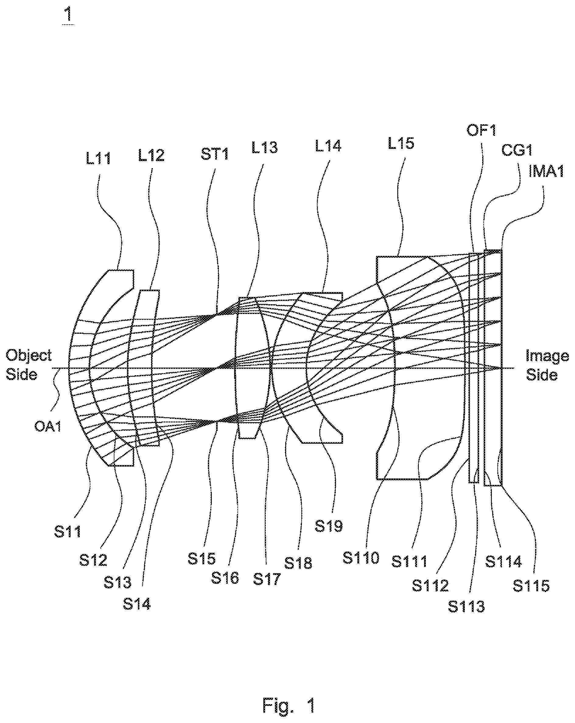
is a lens layout and optical path diagram of a lens assembly in accordance with a first embodiment of the invention;
A depicts a longitudinal aberration diagram of the lens assembly in accordance with the first embodiment of the invention;
B is a field curvature diagram of the lens assembly in accordance with the first embodiment of the invention;
C is a distortion diagram of the lens assembly in accordance with the first embodiment of the invention;
D is a relative illumination diagram of the lens assembly in accordance with the first embodiment of the invention;
is a lens layout and optical path diagram of a lens assembly in accordance with a second embodiment of the invention;
A depicts a longitudinal aberration diagram of the lens assembly in accordance with the second embodiment of the invention;
B is a field curvature diagram of the lens assembly in accordance with the second embodiment of the invention;
C is a distortion diagram of the lens assembly in accordance with the second embodiment of the invention;
D is a relative illumination diagram of the lens assembly in accordance with the second embodiment of the invention;
is a lens layout and optical path diagram of a lens assembly in accordance with a third embodiment of the invention;
A depicts a longitudinal aberration diagram of the lens assembly in accordance with the third embodiment of the invention;
B is a field curvature diagram of the lens assembly in accordance with the third embodiment of the invention;
C is a distortion diagram of the lens assembly in accordance with the third embodiment of the invention; and
D is a relative illumination diagram of the lens assembly in accordance with the third embodiment of the invention.
DETAILED DESCRIPTION OF THE INVENTION
The following description is made for the purpose of illustrating the general principles of the invention and should not be taken in a limiting sense. The scope of the invention is best determined by reference to the appended claims.
The present invention provides a lens assembly including a first lens, a second lens, a third lens, a fourth lens, and a fifth lens. The first lens is with negative refractive power. The second lens is with positive refractive power. The third lens is with positive refractive power. The fourth lens is with negative refractive power and includes a convex surface facing an object side and a concave surface facing an image side. The fifth lens is with negative refractive power and includes a concave surface facing the object side. The first lens, the second lens, the third lens, the fourth lens, and the fifth lens are arranged in order from the object side to the image side along an optical axis.
The present invention provides another lens assembly including a first lens, a second lens, a third lens, a fourth lens, and a fifth lens. The first lens is with negative refractive power. The second lens is with positive refractive power. The third lens is with positive refractive power. The fourth lens is with negative refractive power and includes a convex surface facing an object side and a concave surface facing an image side. The fifth lens is with negative refractive power and includes a convex surface facing the image side. The first lens, the second lens, the third lens, the fourth lens, and the fifth lens are arranged in order from the object side to the image side along an optical axis.
Referring to Table 1, Table 2, Table 4, Table 5, Table 7, and Table 8, wherein Table 1, Table 4, and Table 7 show optical specifications in accordance with a first, second, and third embodiments of the invention respectively and Table 2, Table 5, and Table 8 show aspheric coefficients of each aspheric surface in Table 1, Table 4, and Table 7 respectively.
, , and are lens layout and optical path diagrams of the lens assembly in accordance with the first, second, and third embodiments of the invention respectively. The first lens L 11 , L 21 , L 31 are meniscus lens with negative refractive power and made of glass material, wherein the object side surfaces S 11 , S 21 , S 31 are convex surfaces, the image side surfaces S 12 , S 22 , S 32 are concave surfaces, and all of the object side surfaces S 11 , S 21 , S 31 and the image side surfaces S 12 , S 22 , S 32 are spherical surfaces.
The second lens L 12 , L 22 , L 32 are meniscus lens with positive refractive power and made of plastic material, wherein the object side surfaces S 13 , S 23 , S 33 are convex surfaces, the image side surfaces S 14 , S 24 , S 34 are concave surfaces, wherein all of the object side surfaces S 13 , S 23 , S 33 and the image side surfaces S 14 , S 24 , S 34 are aspheric surfaces.
The third lens L 13 , L 23 , L 33 are biconvex lens with positive refractive power and made of glass material, wherein the object side surfaces S 16 , S 26 , S 36 are convex surfaces, the image side surfaces S 17 , S 27 , S 37 are convex surfaces, wherein all of the object side surfaces S 16 , S 26 , S 36 and the image side surfaces S 17 , S 27 , S 37 are spherical surfaces.
The fourth lens L 14 , L 24 , L 34 are meniscus lens with negative refractive power and made of plastic material, wherein the object side surfaces S 18 , S 28 , S 38 are convex surfaces, the image side surfaces S 19 , S 29 , S 39 are concave surfaces, wherein all of the object side surfaces S 18 , S 28 , S 38 and the image side surfaces S 19 , S 29 , S 39 are aspheric surfaces.
The fifth lens L 15 , L 25 , L 35 are meniscus lens with negative refractive power and made of plastic material, wherein the object side surfaces S 10 , S 210 , S 310 are concave surfaces, the image side surfaces S 111 , S 211 , S 311 are convex surfaces, wherein all of the object side surfaces S 110 , S 210 , S 310 and the image side surfaces S 111 , S 211 , S 311 are aspheric surfaces.
In addition, the lens assembly 1 , 2 , 3 satisfy at least one of the following conditions: 3< f 2 /f 3 <4; (1) 4.8<| f 4 /f 3 |<5.7; (2) 5.2<| f 5 /f 3 |<6.5; (3) 3.7< R 31 /R 12 <6.1; (4) −3.5< R 31 /R 32 <−1.9; (5) −14.8< R 52 /R 42 <−10.7; (6)
wherein f 2 is an effective focal length of the second lens L 12 , L 22 , L 32 for the first to third embodiments, f 3 is an effective focal length of the third lens L 13 , L 23 , L 33 for the first to third embodiments, f 4 is an effective focal length of the fourth lens L 14 , L 24 , L 34 for the first to third embodiments, f 5 is an effective focal length of the fifth lens L 15 , L 25 , L 35 for the first to third embodiments, R 12 is a radius of curvature of the image side surface S 12 , S 22 , S 32 of the first lens L 11 , L 21 , L 31 for the first to third embodiments, R 31 is a radius of curvature of the object side surface S 16 , S 26 , S 36 of the third lens L 13 , L 23 , L 33 for the first to third embodiments, R 32 is a radius of curvature of the image side surface S 17 , S 27 , S 37 of the third lens L 13 , L 23 , L 33 for the first to third embodiments, R 42 is a radius of curvature of the image side surface S 19 , S 29 , S 39 of the fourth lens L 14 , L 24 , L 34 for the first to third embodiments, R 52 is a radius of curvature of the image side surface S 111 , S 211 , S 311 of the fifth lens L 15 , L 25 , L 35 for the first to third embodiments. Making the lens assembly 1 , 2 , 3 can effectively correct aberration and effectively increase resolution.
A detailed description of a lens assembly in accordance with a first embodiment of the invention is as follows. Referring to , the lens assembly 1 includes a first lens L 11 , a second lens L 12 , a stop ST 1 , a third lens L 13 , a fourth lens L 14 , a fifth lens L 15 , an optical filter OF 1 , and cover glass CG 1 , all of which are arranged in order from an object side to an image side along an optical axis OA 1 . In operation, an image of light rays from the object side is formed at an image plane IMA 1 .
According to the foregoing description, wherein: both of the object side surface S 112 and image side surface S 113 of the optical filter OF are plane surfaces; and both of the object side surface S 114 and image side surface S 115 of the cover glass CG 1 are plane surfaces.
With the above design of the lenses and stop ST 1 and at least any one of the conditions (1)-(6) satisfied, the lens assembly 1 can effectively correct aberration and effectively increase resolution.
If the value of the condition (5) R 31 /R 32 is greater than −1.9, the correction aberration capability of the third lens L 13 is reduced, and the shape of the third lens L 13 cannot be effectively controlled. Therefore, the value of R 31 /R 32 must be at least less than −1.9, so the optimal range of effect is −3.5<R 31 /R 32 <−1.9, within this range, the shape of the third lens L 13 can be effectively controlled, constrain the refractive strength of the third lens L 13 , and enhance the aberration correction ability of the third lens L 13 .
Table 1 shows the optical specification of the lens assembly 1 in .
TABLE 1
Effective Focal Length = 4.964 mm F-number = 2.2
Total Lens Length = 10.029 mm Field of View = 60.502 Degrees
Radius of Effective
Surface Curvature Thickness Focal Length
Number (mm) (mm) Nd Vd (mm) Remark
S11 3.301 0.427 1.729 54.680 −11.292 The First Lens
L11
S12 2.203 0.900
S13 4.763 0.565 1.661 20.373 16.653 The Second
Lens L12
S14 8.292 1.506
S15 ∞ 0.431 Stop ST1
S16 12.515 0.818 1.729 54.680 4.245 The Third
Lens L13
S17 −3.901 0.035
S18 2.277 0.800 1.661 20.372 −23.389 The Fourth
Lens L14
S19 1.705 2.063
S110 −8.857 1.632 1.535 56.115 −27.04 The Fifth
Lens L15
S111 −25.000 0.1
S112 ∞ 0.21 1.517 64.167 Optical Filter
OF1
S113 ∞ 0.142
S114 ∞ 0.4 1.517 64.167 Cover Glass
CG1
The aspheric surface sag z of each aspheric surface in table 1 can be calculated by the following formula: z=ch 2 /{1+[1−( k+ 1) c 2 h 2 ] 1/2 }+Ah 4 +Bh 6 +Ch 8 +Dh 10 +Eh 12 where c is curvature, h is the vertical distance from the lens surface to the optical axis, k is conic constant and A, B, C, D, and E are aspheric coefficients.
In the first embodiment, the conic constant k and the aspheric coefficients A, B, C, D, E of each aspheric surface are shown in Table 2.
TABLE 2
Surface
Number k A B C D E
S13 3.494 −7.035E−3 −4.895E−4 −3.954E−4 0 0
S14 17.319 −3.814E−3 −6.135E−4 −2.720E−4 0 0
S18 0.323 −0.01034 4.7153E−3 −6.138E−3 2.2268E−3 −3.813E−4
S19 −0.498 6.8443E−3 5.5087E−3 −6.498E−3 3.5907E−3 −7.947E−4
S110 0 −7.168E−3 −5.262E−3 2.383E−3 −6.473E−4 7.4037E−5
S111 0 6.845E−3 −5.38E−3 2.1281E−4 4.4744E−5 −4.968E−6
Table 3 shows the parameters and condition values for conditions (1)-(6) in accordance with the first embodiment of the invention. It can be seen from Table 3 that the lens assembly 1 of the first embodiment satisfies the conditions (1)-(6).
TABLE 3
f 2 /f 3 3.92 |f 4 /f 3 | 5.51 |f 5 /f 3 | 6.37
R 31 /R 12 5.68 R 31 /R 32 −3.21 R 52 /R 42 −14.66
By the above arrangements of the lenses and stop ST 1 , the lens assembly 1 of the first embodiment can meet the requirements of optical performance as seen in A- 2 D , wherein A shows a longitudinal aberration diagram of the lens assembly 1 in accordance with the first embodiment of the invention, B shows a field curvature diagram of the lens assembly 1 in accordance with the first embodiment of the invention, C shows a distortion diagram of the lens assembly 1 in accordance with the first embodiment of the invention, and D shows a relative illumination diagram of the lens assembly 1 in accordance with the first embodiment of the invention. It can be seen from A that the longitudinal aberration in the lens assembly 1 of the first embodiment ranges from −0.01 mm to 0.03 mm. It can be seen from B that the field curvature of tangential direction and sagittal direction in the lens assembly 1 of the first embodiment ranges from −0.02 mm to 0.07 mm. It can be seen from C that the distortion in the lens assembly 1 of the first embodiment ranges from −6% to 2%. It can be seen from D that the relative illumination in the lens assembly 1 of the first embodiment ranges from 0.8 to 1.0.
It is obvious that the longitudinal aberration, the field curvature and the distortion of the lens assembly 1 of the first embodiment can be corrected effectively, and the relative illumination of the lens assembly 1 of the first embodiment can meet the requirement. Therefore, the lens assembly 1 of the first embodiment is capable of good optical performance.
Referring to , is a lens layout and optical path diagram of a lens assembly in accordance with a second embodiment of the invention. The lens assembly 2 includes a first lens L 21 , a second lens L 22 , a stop ST 2 , a third lens L 23 , a fourth lens L 24 , a fifth lens L 25 , an optical filter OF 2 , and cover glass CG 2 , all of which are arranged in order from an object side to an image side along an optical axis OA 2 . In operation, an image of light rays from the object side is formed at an image plane IMA 2 .
According to the foregoing description, wherein: both of the object side surface S 212 and image side surface S 213 of the optical filter OF 2 are plane surfaces; and both of the object side surface S 214 and image side surface S 215 of the cover glass CG 2 are plane surfaces.
With the above design of the lenses and stop ST 2 and at least any one of the conditions (1)-(6) satisfied, the lens assembly 2 can effectively correct aberration and effectively increase resolution.
If the value of the condition (1) f 2 /f 3 is greater than 4, it makes the correction aberration capability of the lens assembly poor. Therefore, the value of f 2 /f 3 must be at least less than 4, so the optimal range of effect is 3<f 2 /f 3 <4, and meeting this range has the best corrected aberration condition and helps to reduce sensitivity.
Table 4 shows the optical specification of the lens assembly 2 in .
TABLE 4
Effective Focal Length = 4.928 mm F-number = 2.2
Total Lens Length = 9.802 mm Field of View = 60.538 Degrees
Radius of Effective
Surface Curvature Thickness Focal Length
Number (mm) (mm) Nd Vd (mm) Remark
S21 3.436 0.464 1.729 54.680 −8.838 The First Lens
L21
S22 2.101 0.764
S23 4.461 0.517 1.661 20.373 13.778 The Second
Lens L22
S24 8.727 1.134
S25 ∞ 0.529 Stop ST2
S26 12.487 0.971 1.729 54.680 4.046 The Third
Lens L23
S27 −3.647 0.025
S28 2.443 0.799 1.661 20.372 −22.653 The Fourth
Lens L24
S29 1.822 2.052
S210 −7.256 1.5 1.535 56.115 −22.584 The Fifth
Lens L25
S211 −20 0.2
S212 ∞ 0.21 1.517 64.167 Optical Filter
OF2
S213 ∞ 0.237
S214 ∞ 0.4 1.517 64.167 Cover Glass
CG2
S215 ∞ 0
The definition of aspheric surface sag z of each aspheric surface in table 4 is the same as that of in Table 1, and is not described here again.
In the second embodiment, the conic constant k and the aspheric coefficients A, B, C, D, E of each aspheric surface are shown in Table 5.
TABLE 5
Surface
Number k A B C D E
S23 −8.551 9.4756E−3 −1.299E−3 −4.74E−4 0 0
S24 21.26 −1.928E−3 −1.698E−4 −6.55E−4 0 0
S28 0.498 −9.622E−3 6.5697E−3 −6.641E−3 2.3831E−3 −3.835E−4
S29 −0.767 0.012819 0.011993 −0.010289 5.8326E−3 −1.204E−3
S210 0 −0.010666 −7.382E−3 3.6848E−3 −1.143E−3 1.4814E−4
S211 0 5.5972E−4 −5.015E−3 4.8846E−4 −9.062E−6 −2.562E−6
Table 6 shows the parameters and condition values for conditions (1)-(6) in accordance with the second embodiment of the invention. It can be seen from Table 6 that the lens assembly 2 of the second embodiment satisfies the conditions (1)-(6).
TABLE 6
f 2 /f 3 3.41 |f 4 /f 3 | 5.60 |f 5 /f 3 | 5.58
R 31 /R 12 5.94 R 31 /R 32 −3.42 R 52 /R 42 −10.98
By the above arrangements of the lenses and stop ST 2 , the lens assembly 2 of the second embodiment can meet the requirements of optical performance as seen in A- 4 D , wherein A shows a longitudinal aberration diagram of the lens assembly 2 in accordance with the second embodiment of the invention, B shows a field curvature diagram of the lens assembly 2 in accordance with the second embodiment of the invention, C shows a distortion diagram of the lens assembly 2 in accordance with the second embodiment of the invention, and D shows a relative illumination diagram of the lens assembly 2 in accordance with the second embodiment of the invention. It can be seen from A that the longitudinal aberration in the lens assembly 2 of the second embodiment ranges from −0.01 mm to 0.04 mm. It can be seen from B that the field curvature of tangential direction and sagittal direction in the lens assembly 2 of the second embodiment ranges from −0.02 mm to 0.09 mm. It can be seen from C that the distortion in the lens assembly 2 of the second embodiment ranges from −5% to 1%. It can be seen from D that the relative illumination in the lens assembly 2 of the second embodiment ranges from 0.8 to 1.0.
It is obvious that the longitudinal aberration, the field curvature and the distortion of the lens assembly 2 of the second embodiment can be corrected effectively, and the relative illumination of the lens assembly 2 of the second embodiment can meet the requirement. Therefore, the lens assembly 2 of the second embodiment is capable of good optical performance.
Referring to , is a lens layout and optical path diagram of a lens assembly in accordance with a third embodiment of the invention. The lens assembly 3 includes a first lens L 31 , a second lens L 32 , a stop ST 3 , a third lens L 33 , a fourth lens L 34 , a fifth lens L 35 , an optical filter OF 3 , and cover glass CG 3 , all of which are arranged in order from an object side to an image side along an optical axis OA 3 . In operation, an image of light rays from the object side is formed at an image plane IMA 3 .
According to the foregoing description, wherein: both of the object side surface S 312 and image side surface S 313 of the optical filter OF 3 are plane surfaces; and both of the object side surface S 314 and image side surface S 315 of the cover glass CG 3 are plane surfaces.
With the above design of the lenses and stop ST 3 and at least any one of the conditions (1)-(6) satisfied, the lens assembly 3 can effectively correct aberration and effectively increase resolution.
If the value of the condition (2) |f 4 /f 3 | is less than 4.8, it makes the correction aberration capability of the lens assembly poor. Therefore, the value of |f 4 /f 3 | must be at least greater than 4.8, so the optimal range of effect is 4.8<|f 4 /f 3 |<5.7, and meeting this range has the best corrected aberration condition and helps to reduce sensitivity.
Table 7 shows the optical specification of the lens assembly 3 in .
TABLE 7
Effective Focal Length = 4.936 mm F-number = 2.2
Total Lens Length = 10.125 mm Field of View = 60.542 Degrees
Radius of Effective
Surface Curvature Thickness Focal Length
Number (mm) (mm) Nd Vd (mm) Remark
S31 3.669 0.468 1.729 54.680 −8.621 The First Lens
L31
S32 2.178 0.867
S33 4.804 0.584 1.661 20.373 12.821 The Second
Lens L32
S34 11.226 1.525
S35 ∞ 0.331 Stop ST3
S36 8.392 0.849 1.729 54.680 4.044 The Third
Lens L33
S37 −4.231 0.046
S38 2.404 0.757 1.661 20.372 −19.695 The Fourth
Lens L34
S39 1.77 1.95
S310 −7.587 1.701 1.535 56.115 −21.448 The Fifth
Lens L35
S311 −25 0.2
S312 ∞ 0.21 1.517 64.167 Optical Filter
OF3
S313 ∞ 0.237
S314 ∞ 0.4 1.517 64.167 Cover Glass
CG3
S315 ∞ 0
The definition of aspheric surface sag z of each aspheric surface in table 7 is the same as that of in Table 1, and is not described here again.
In the third embodiment, the conic constant k and the aspheric coefficients A, B, C, D, E of each aspheric surface are shown in Table 8.
TABLE 8
Surface
Number k A B C D E
S33 −0.306 −1.315E−3 9.776E−4 −5.59E−4 0 0
S34 32.198 −1.431103 5.6554E−4 −6.524E−4 0 0
S38 0.597 −0.010428 8.7415E−3 −9.823E−3 3.8306E−3 −6.524E−4
S39 −0.579 0.01191 0.014702 −0.015085 8.873E−3 −1.918E−3
S310 0 −0.011332 −7.542E−3 4.262E−3 −1.451E−3 1.9905E−4
S311 0 −1.54E−3 −4.374E−3 3.9897E−4 −4.561E−6 −2.383E−6
Table 9 shows the parameters and condition values for conditions (1)-(6) in accordance with the third embodiment of the invention. It can be seen from Table 9 that the lens assembly 3 of the third embodiment satisfies the conditions (1)-(6).
TABLE 9
f 2 /f 3 3.17 |f 4 /f 3 | 4.87 |f 5 /f 3 | 5.30
R 31 /R 12 3.85 R 31 /R 32 −1.98 R 52 /R 42 −14.12
By the above arrangements of the lenses and stop ST 3 , the lens assembly 3 of the third embodiment can meet the requirements of optical performance as seen in A- 6 D , wherein A shows a longitudinal aberration diagram of the lens assembly 3 in accordance with the third embodiment of the invention, B shows a field curvature diagram of the lens assembly 3 in accordance with the third embodiment of the invention, C shows a distortion diagram of the lens assembly 3 in accordance with the third embodiment of the invention, and D shows a relative illumination diagram of the lens assembly 3 in accordance with the third embodiment of the invention. It can be seen from A that the longitudinal aberration in the lens assembly 3 of the third embodiment ranges from −0.01 mm to 0.04 mm. It can be seen from B that the field curvature of tangential direction and sagittal direction in the lens assembly 3 of the third embodiment ranges from −0.02 mm to 0.10 mm. It can be seen from C that the distortion in the lens assembly 3 of the third embodiment ranges from −5% to 1%. It can be seen from D that the relative illumination in the lens assembly 3 of the third embodiment ranges from 0.8 to 1.0.
It is obvious that the longitudinal aberration, the field curvature and the distortion of the lens assembly 3 of the third embodiment can be corrected effectively, and the relative illumination of the lens assembly 3 of the third embodiment can meet the requirement. Therefore, the lens assembly 3 of the third embodiment is capable of good optical performance.
The conditions of the present invention are centered around −3.5<R 31 /R 32 <−1.9, 3<f 2 /f 3 <4, 4.8<|f 4 /f 3 |<5.7, and the values of the embodiments of the present invention also fall within the scope of the remaining conditions. Condition −3.5<R 31 /R 32 <−1.9, which helps to enhance aberration correction capability of the third lens. Condition 3<f 2 /f 3 <4, with the best corrected aberration conditions. Condition 4.8<|f 4 /f 3 |<5.7, which can help reduce sensitivity.
While the invention has been described by way of example and in terms of the preferred embodiment(s), it is to be understood that the invention is not limited thereto. On the contrary, it is intended to cover various modifications and similar arrangements and procedures, and the scope of the appended claims therefore should be accorded the broadest interpretation so as to encompass all such modifications and similar arrangements and procedures.
Figures (15)
Citations
This patent cites (17)
- US5493446
- US5946505
- US8908289
- US9784946
- US20030103275
- US20130286488
- US20140240851
- US20180067281
- US20180314054
- US20190041610
- US20190219798
- US20200355889
- US206990888
- US109324387
- US208654420
- US2005275280
- US2012132456