Electronic Device for Determining State of Charge of Battery Device, and Method of Operating the Electronic Device
Abstract
A battery device includes a first battery and a second battery connected in series. An electronic device for determining a state of charge of the battery device includes a sense resistor connected in series to the second battery, and a fuel gauge. The fuel gauge is configured to determine the state of charge of the battery device based on a first terminal voltage of the first battery, a first calculation current of the first battery, a second terminal voltage of the second battery, and a measurement current of the second battery measured through the sense resistor. The fuel gauge calculates a second calculation current of the second battery using a battery parameter of an equivalent circuit model, corrects the battery parameter when a difference between the measurement current and the second calculation current is not less than a threshold value, and calculates the first calculation current using the battery parameter or a corrected battery parameter.
Claims (20)
1. An electronic device comprising: a battery device including: a first battery and a second battery connected to each other in series, a first terminal connected to a high voltage node of the first battery, a second terminal connected to a connection node between the first battery and the second battery, and a third terminal connected to a low voltage node of the second battery, and a charger IC configured to charge the battery device by providing a first charge current to the first terminal in a first charge mode and providing a second charge current to the second terminal in a second charge mode; a sense resistor configured to be connected between the third terminal and a ground terminal; and a fuel gauge configured to determine a state of charge of the battery device based on a first terminal voltage of the first battery, a second terminal voltage of the second battery, and a measurement current of the second battery measured through the sense resistor.
16. A battery device configured to be connected to an electronic device, the battery device comprising: a first battery and a second battery connected in series; a first terminal connected to a high voltage node of the first battery; a second terminal connected to a connection node between the first battery and the second battery; a third terminal; a sense resistor connected between a low voltage node of the second battery and the third terminal; and a fuel gauge configured to determine a state of charge of the battery device by measuring a current flowing in the second battery through the sense resistor as a measurement current and by sensing a first terminal voltage of the first battery and a second terminal voltage of the second battery, wherein the battery device is configured to receive a first charging current from the electronic device through the first terminal in a first charge mode, receive a second charging current from the electronic device through the second terminal in a second charge mode, and provide a system current to the electronic device through the second terminal in a discharge mode.
19. An integrated circuit (IC) configured to be connected to a battery device including a first battery and a second battery connected to each other in series, the IC comprising: a first charger connected to between an input voltage terminal and a first terminal of the battery device, the first charger configured to directly charge the battery device by providing a first charge current to the first terminal using an input voltage received from the input voltage terminal in a first charge mode; a second charger connected between the input voltage terminal and a second terminal of the battery device, the second charger configured to provide a second charge current to the second terminal using the input voltage received from the input voltage terminal in a second charger mode; a sense resistor configured to be connected between a third terminal of the battery device and a ground terminal; and a fuel gauge configured to determine a state of charge of the battery device based on a first terminal voltage of the first battery, a second terminal voltage of the second battery, and a measurement current of the second battery measured through the sense resistor, wherein the first terminal is connected to a high voltage node of the first battery, the second terminal is connected to a connection node between the first battery and the second battery, and the third terminal is connected to a low voltage node of the second battery.
Show 17 dependent claims
2. The electronic device of claim 1 , wherein the charger IC includes a first charger connected to between an input voltage terminal and the first terminal, and wherein the first charger is configured to directly charge the battery device by providing the first charge current to the first terminal using an input voltage received from the input voltage terminal in the first charge mode.
3. The electronic device of claim 2 , wherein the first charger includes a direct charger having at least one switch connected between the input voltage terminal and the first terminal.
4. The electronic device of claim 2 , wherein the charger IC further includes a second charger connected between the input voltage terminal and the second terminal, and wherein the second charger is configured to provide the second charge current to the second terminal using the input voltage received from the input voltage terminal in the second charge mode.
5. The electronic device of claim 4 , wherein the second charger includes a switching charger.
6. The electronic device of claim 5 , wherein the switching charger includes: a first switch, a second switch, and a third switch connected to each other in series between the input voltage terminal and the ground terminal; an inductor connected between a switching node, between the second switch and the third switch, and an output node; and a fourth switch connected between the output node and the second terminal.
7. The electronic device of claim 4 , wherein the first charge mode corresponds to a high speed charge mode, and the second charger is deactivated in the first charge mode, and wherein the second charge mode corresponds to a normal charge mode, and the first charger is deactivated in the second charge mode.
8. The electronic device of claim 4 , wherein the first battery includes a first battery cell, the second battery includes a second battery cell, and the battery device includes a multi-cell battery.
9. The electronic device of claim 1 , wherein the charger IC includes a balancing circuit electrically connected to the battery device, and wherein the balancing circuit is configured to balance voltages of the first battery and the second battery.
10. The electronic device of claim 1 , wherein the fuel gauge is further configured to: calculate a first calculation current by using the first terminal voltage and a first battery parameter of an equivalent circuit model of the second battery, and determine the state of charge of the battery device based on the first terminal voltage, the first calculation current, the second terminal voltage, and the measurement current.
11. The electronic device of claim 1 , wherein the fuel gauge is further configured to: calculate a second calculation current of the second battery by using a first battery parameter of an equivalent circuit model of the second battery and the second terminal voltage, correct the first battery parameter to a second battery parameter when a difference between the measurement current and the second calculation current is greater than or equal to a threshold value, calculate a first calculation current by using the first terminal voltage and the first battery parameter or the second battery parameter, and determine the state of charge of the battery device based on the first terminal voltage, the first calculation current, the second terminal voltage, and the measurement current.
12. The electronic device of claim 11 , wherein the fuel gauge is further configured to: determine a first state of charge of the first battery based on the first calculation current of the first battery, determine a second state of charge of the second battery based on the second calculation current or the measurement current of the second battery, and determine the state of charge of the battery device based on the first state of charge and the second state of charge.
13. The electronic device of claim 11 , wherein the fuel gauge is further configured to: calculate the first calculation current by using the second battery parameter and the first terminal voltage when the difference between the measurement current and the second calculation current is greater than or equal to the threshold value, and calculate the first calculation current by using the first battery parameter and the first terminal voltage when the difference between the measurement current and the second calculation current is less than the threshold value.
14. The electronic device of claim 11 , wherein, when the first terminal voltage and the second terminal voltage do not reach a balanced state, the fuel gauge is further configured to determine the state of charge of the battery device based on the second calculation current or based on the measurement current and the first calculation current.
15. The electronic device of claim 1 , wherein, when the first terminal voltage and the second terminal voltage reach a balanced state, the fuel gauge is further configured to determine a voltage level of the balanced state of the first terminal voltage and the second terminal voltage as a common open circuit voltage of the first battery and the second battery and determine the state of charge of the battery device based on the common open circuit voltage.
17. The battery device of claim 16 , wherein the state of charge of the battery device is determined based on the first terminal voltage of the first battery, a first calculation current of the first battery, the second terminal voltage of the second battery, and the measurement current of the second battery, and the first calculation current is calculated by using the first terminal voltage and a first battery parameter of an equivalent circuit model of the second battery.
18. The battery device of claim 17 , wherein a second calculation current of the second battery is calculated by using the first battery parameter and the second terminal voltage of the second battery, so that the first battery parameter is corrected to a second battery parameter when a difference between the measurement current of the second battery and the second calculation current of the second battery is greater than or equal to a threshold value, and the first calculation current is calculated by using the first terminal voltage and the first battery parameter or the second battery parameter.
20. The IC of claim 19 , wherein the first charge mode corresponds to a high speed charge mode, and the second charger is deactivated in the first charge mode, and wherein the second charge mode corresponds to a normal charge mode, and the first charger is deactivated in the second charge mode.
Full Description
Show full text →
CROSS-REFERENCE TO RELATED APPLICATION
This is a Continuation of U.S. application Ser. No. 16/705,467, filed Dec. 6, 2019, and a claim of priority under 35 U.S.C. § 119 is made to Korean Patent Application No. 10-2019-0027014, filed on Mar. 8, 2019 in the Korean Intellectual Property Office, the disclosure of which is incorporated herein in its entirety by reference.
BACKGROUND
1. Technical Field
The present disclosure relates to an electronic device. More particularly, the present disclosure relates to an electronic device for determining a state of charge of a battery device and a method of operating the electronic device.
2. Description of the Related Art
Portable electronic devices such as mobile phones include batteries. As the fifth generation (5G) era for cellular network technology has arrived, the power required by mobile phones has increased. Since a usage time of 5G mobile phones is limited due to the current battery capacity, increased capacity of the battery is increasingly demanded. Accordingly, the importance of fast charging of the battery of the mobile phones has also increased. Since it is difficult to measure energy actually stored in the battery, the state of charge (SOC) of the battery may be used as a parameter (e.g., a basis) for measuring energy available in the battery.
SUMMARY
According to aspects of the present disclosure, an electronic device and a method of operating the electronic device are provided. A state of charge of a battery device can be efficiently determined with the electronic device and the method of operating the electronic device.
According to another aspect of the present disclosure, a battery device capable of efficiently determining a state of charge of the battery device is provided.
According to an aspect of the present disclosure, a battery device includes a first battery and a second battery connected in series. An electronic device is provided for determining a state of charge of the battery device. The electronic device includes a sense resistor and a fuel gauge. A measurement current of the second battery is measured through the sense resistor. The sense resister is configured to be connected in series to the second battery. The fuel gauge is configured to determine the state of charge of the battery device based on a first terminal voltage of the first battery, a first calculation current of the first battery, a second terminal voltage of the second battery, and the measurement current of the second battery. The fuel gauge is further configured to calculate a second calculation current of the second battery by using a first battery parameter of an equivalent circuit model of the second battery and the second terminal voltage. The fuel gauge is also configured to correct the first battery parameter to a second battery parameter when a difference between the measurement current and the second calculation current is greater than or equal to a threshold value, and to calculate the first calculation current by using the first terminal voltage and the first battery parameter or the second battery parameter.
According to another aspect of the present disclosure, a battery device includes a first battery and a second battery connected in series. A method of operating an electronic device for determining a state of charge of the battery device includes obtaining a measurement current of the second battery, measured through a sense resistor serially connected to the second battery, and calculating a calculation current of the second battery by using a first battery parameter of an equivalent circuit model of the second battery and a second terminal voltage of the second battery. The method of operating the electronic device also includes correcting the first battery parameter to a second battery parameter when a difference between the measurement current and the calculation current is greater than or equal to a threshold value, and calculating a current of the first battery by using the first terminal voltage of the first battery and the first battery parameter or the second battery parameter. The state of charge of the battery device is determined based on the current of the first battery and the measurement current of the second battery or the calculation current of the second battery.
According to another aspect of the present disclosure, a battery device is connectable to an electronic device and includes a first battery and a second battery connected in series, a first terminal connected to a high voltage node of the first battery, a second terminal connected to a connection node between the first battery and the second battery, and a third terminal connected to a low voltage node of the second battery. The battery device is configured to receive a first charging current from the electronic device through the first terminal in a first charge mode, receive a second charging current from the electronic device through the second terminal in a second charge mode, and provide a system current to the electronic device through the second terminal in a discharge mode.
BRIEF DESCRIPTION OF THE DRAWINGS
Embodiments of the inventive concept(s) of the present disclosure will be more clearly understood from the following detailed description taken in conjunction with the accompanying drawings in which:
is a block diagram illustrating an electronic device according to an embodiment;
illustrates an equivalent circuit for a battery model according to an embodiment;
illustrates another equivalent circuit for another battery model according to an embodiment;
illustrates another equivalent circuit for another battery model according to an embodiment;
is a block diagram illustrating an electronic device according to an embodiment;
illustrates a charger integrated circuit (IC) of in more detail, according to an embodiment;
illustrates a first charge mode performed by a first charger, according to an embodiment;
illustrates a second charge mode performed by a second charger, according to an embodiment;
illustrates a discharge mode of an electronic device according to an embodiment;
is a block diagram illustrating an electronic device according to another embodiment;
is a flowchart illustrating a method of operating an electronic device for determining a state of charge (SOC) of a battery, according to an embodiment;
is a flowchart illustrating in more detail a method of operating an electronic device for determining an SOC of a battery, according to an embodiment;
is a flowchart illustrating a method of operating an electronic device for determining an SOC of a battery, according to an embodiment;
illustrates a balancing operation for a first battery and a second battery, according to an embodiment;
is a graph showing voltage against time with respect to the first battery and the second battery, according to an embodiment;
is a flowchart illustrating a method of operating an electronic device for determining an SOC of a battery, according to an embodiment;
illustrates a battery device according to an embodiment;
illustrates a battery device according to an embodiment;
illustrates a battery device according to an embodiment;
illustrates a battery device according to an embodiment; and
is a block diagram illustrating an electronic device according to an embodiment.
DETAILED DESCRIPTION OF THE EMBODIMENTS
Hereinafter, embodiments of the inventive concept(s) of the present disclosure are described in detail with reference to the accompanying drawings.
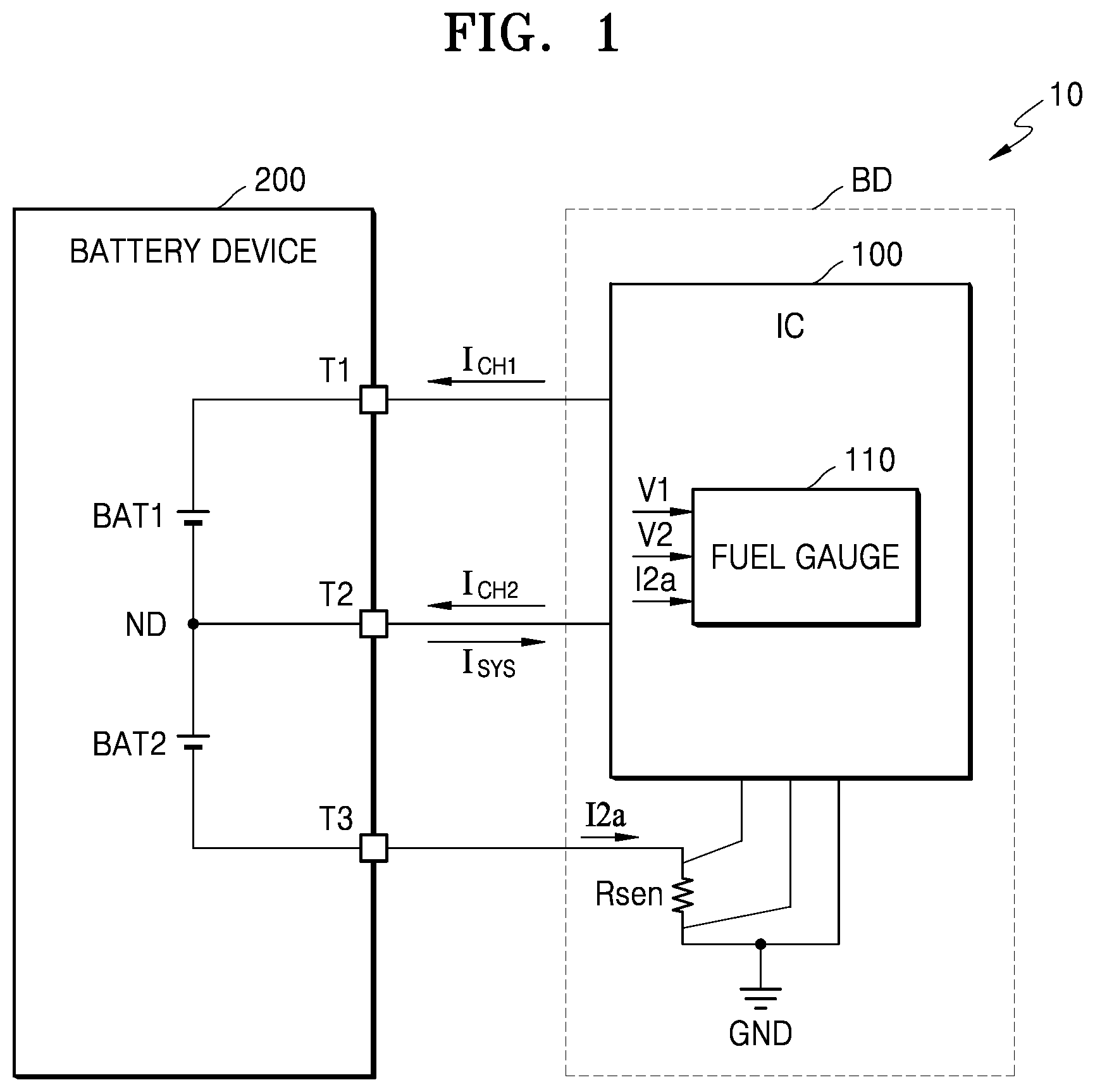
is a block diagram illustrating an electronic device 10 according to an embodiment.
Referring to , the electronic device 10 may include a battery device 200 . In an embodiment, the battery device 200 may be embedded in the electronic device 10 . In an embodiment, the battery device 200 may be detachable from the electronic device 10 . For example, the electronic device 10 may include a smart phone, a tablet personal computer (PC), a mobile phone, a personal digital assistant (PDA), a laptop, a wearable device, a global positioning system (GPS), and a mobile device such as an electronic book terminal, a digital broadcasting terminal, an MP3 player, and a digital camera. For example, the electronic device 10 may be an electric vehicle.
The battery device 200 may include a first battery BAT 1 and a second battery BAT 2 connected to each other in series. In addition, the battery device 200 may further include a first terminal T 1 , a second terminal T 2 , and a third terminal T 3 . Accordingly, the battery device 200 may be a 3-terminal battery. The first battery BAT 1 may have a cathode or positive side and an anode or negative side. The second battery BAT 2 may have a cathode or positive side and an anode or negative side. The first terminal T 1 may be connected to a high voltage node of the first battery BAT 1 , the second terminal T 2 may be connected to a connection node ND between the first battery BAT 1 and the second battery BAT 2 , and the third terminal T 3 may be connected to a low voltage node of the second battery BAT 2 . The high voltage node of the first battery BAT 1 may be the cathode or positive side of the first battery BAT 1 . The low voltage node of the second battery BAT 2 may be the anode or negative side of the second battery BAT 2 .
The battery device 200 may receive a first charging current I CH1 through the first terminal T 1 in a first charge mode and may receive a second charging current I CH2 through the second terminal T 2 in a second charge mode. The battery device 200 may provide a system current I SYS through the second terminal T 2 in a discharge mode or a battery only mode. Accordingly, the first terminal T 1 may be referred to as a “charging terminal” and used to charge the first battery BAT 1 , and the second terminal T 2 may be referred to as a “charging and discharging terminal” and used to both charge and discharge the battery device 200 .
In some embodiments, the battery device 200 may include three or more batteries connected in series. For example, the battery device 200 may further include at least one additional battery between the first battery BAT 1 and the connection node ND. Also, in some embodiments, the battery device 200 may include three or more batteries connected in series and in parallel. For example, the battery device 200 may further include at least one additional battery connected in parallel with the first battery BAT 1 and/or at least one additional battery connected in parallel with the second battery BAT 2 .
In an embodiment, the first battery BAT 1 may be a first battery cell, the second battery BAT 2 may be a second battery cell, and the battery device 200 may be a multi-cell battery including multiple battery cells connected to each other in series. For example, the battery device 200 may be implemented as a battery pack. In an embodiment, the first battery BAT 1 may be a first battery pack, the second battery BAT 2 may be a second battery pack, and the battery device 200 may be implemented as a battery device including multiple battery packs connected to each other in series. In an embodiment, at least one of the first battery pack and the second battery pack may be a multi-cell battery including multiple battery cells. In an embodiment, at least one of the first battery pack and the second battery pack may be a single-cell battery including only one battery cell.
In addition, the electronic device 10 may further include a fuel gauge 110 and a sense resistor Rsen. The fuel gauge 110 may be implemented as a portion of an IC 100 (integrated circuit) or an IC chip. For example, the IC 100 may be an interface-power management IC (IF-PMIC). The IC 100 and the sense resistor Rsen may be mounted on a printed circuit board BD.
The sense resistor Rsen may be connected in series to the second battery BAT 2 , and specifically, between the third terminal T 3 and a ground terminal GND. Accordingly, the electronic device 10 may measure a current I2a flowing in the second battery BAT 2 through the sense resistor Rsen. In the present specification, the current I2a flowing in the second battery BAT 2 , which is measured through the sense resistor Rsen, will be referred to as a “measurement current I2a”. In , the sense resistor Rsen is represented by one resistor element. However, sense resistors according to the present disclosure are not limited thereto and the sense resistor Rsen may be implemented by any element or combination of elements having a resistance component.
Since the electronic device 10 does not include a sense resistor connected to the first battery BAT 1 , a current flowing in the first battery BAT 1 may not be measured. If the battery device 200 is a two-terminal battery that does not include the second terminal T 2 , a current flowing in the first battery BAT 1 and a current flowing in the second battery BAT 2 will be the same. Therefore, it is possible to measure a current flowing in the first battery BAT 1 and the second battery BAT 2 through one sense resistor Rsen. However, since the battery device 200 according to the present embodiment is a three-terminal battery including the second terminal T 2 , a current flowing in the first battery BAT 1 and a current flowing in the second battery BAT 2 will be different from each other.
The fuel gauge 110 may determine or estimate a state of charge (SOC) of the battery device 200 . Since it is difficult to measure energy actually stored in the battery device 200 , a charge state may be used as a parameter (e.g., a basis) for measuring energy available in the battery device 200 . The SOC may be defined as a percentage (%), as a ratio of the present capacity (the present level of charge) to the maximum capacity (the maximum possible level of charge) of the battery device 200 .
The fuel gauge 110 may be implemented by hardware and/or software that is capable of monitoring the SOC of the battery device 200 . The fuel gauge 110 may implement processes as described herein. In an embodiment, the fuel gauge 110 may determine the SOC of the battery device 200 by monitoring the remaining amount (the present level of charge), the voltage, the current, and/or the temperature of the battery device 200 and thus may be a battery fuel gauge or a battery gauge even though implemented in the IC 100 rather than the battery device 200 .
A first terminal voltage V1 of the first battery BAT 1 may be the measurable voltage between the cathode or positive side and the anode or negative side of the first battery BAT 1 , that is, across the first battery BAT 1 . A second terminal voltage V2 of the second battery BAT 2 may be the measurable voltage between the cathode or positive side and the anode or negative side of the second battery BAT 2 , that is, across the second battery BAT 2 . In the present embodiment, the fuel gauge 110 may determine the SOC of the battery device 200 , based on the first terminal voltage V1 of the first battery BAT 1 , the second terminal voltage V2 of the second battery BAT 2 , and the measurement current I2a flowing in the second battery BAT 2 . As explained below, the fuel gauge 110 may estimate or calculate the current flowing in the first battery BAT 1 , based on the second terminal voltage V2 of the second battery BAT 2 and the measurement current I2a flowing in the second battery BAT 2 .
The fuel gauge 110 may estimate or calculate the current flowing in the first battery BAT 1 , based on a battery model and based on the measurement current I2a flowing in the second battery BAT 2 . Specifically, the fuel gauge 110 may calculate a calculation current of the second battery BAT 2 by using a battery parameter of the battery model and may determine whether to correct the battery parameter based on the difference between the calculation current and the measurement current I2a. For example, the fuel gauge 110 may correct the battery parameter based on battery parameters predetermined according to temperature, load, SOC, and the like. The battery model may be an electric circuit model, and the electric circuit model may be designed based on electrical characteristics experiment and data of a battery. In this case, the electric circuit model is obtained by modelling a battery by electrical characteristics such as resistance and impedance based on the dynamic characteristics and operation principle of the battery. For example, the battery model may be an electro-chemical model. In this case, the electro-chemical model is obtained by modelling a battery based on physical phenomena in an anode of the battery, in a cathode of the battery, and in an electrolyte of the battery. The battery model and a current calculation method using the battery model will be described in more detail with reference to to .
Therefore, even if the electronic device 10 does not include a sense resistor for sensing a current flowing in the first battery BAT 1 , the fuel gauge 110 may calculate a first SOC of the first battery BAT 1 by estimating or calculating the current flowing in the first battery BAT 1 based on a battery model and based on the measurement current I2a flowing in the second battery BAT 2 . Also, the fuel gauge 110 may calculate a second SOC of the second battery BAT 2 based on the measured current I2a flowing in the second battery BAT 2 and may determine the SOC of the battery device 200 based on the first SOC and the second SOC.
In some embodiments, the IC 100 may further include a processor (e.g., a microprocessor) or control logic such as one or more application-specific integrated circuits) and the processor or the control logic may control the fuel gauge 110 . In some embodiments, the electronic device 10 may include a processor or control logic external to the IC 100 and the processor or control logic may control the fuel gauge 110 . In the case of a processor, the processor may execute instructions by which a gauging method of the fuel gauge 110 , e.g., a method of determining an SOC of a battery device, is implemented. Examples of such a method are illustrated in , 12 , 13 , and/or 16 .
illustrates an equivalent circuit for a battery model 20 according to an embodiment.
Referring to , the battery model 20 may be a simple battery model having an internal resistance R int . The internal resistance R int may be caused by internal circuit path resistance and contact resistance of a battery. In this case, the internal resistance R int may be a battery parameter of the battery model 20 . When a current flowing in the battery model 20 is I and a battery voltage is V, an open circuit voltage V OC of the battery model 20 may be expressed as V+I·R int (that is, V OC =V+I·R int ). Accordingly, when the battery model 20 is used, a current I may be calculated from the open circuit voltage V OC and the battery voltage V (that is, I=(V OC −V)/R int ).
Referring to , it may be assumed that battery models of the first battery BAT 1 and the second battery BAT 2 are the same as the battery model 20 . The fuel gauge 110 may calculate a calculation current I2b of the second battery BAT 2 by using the second terminal voltage V2 of the second battery BAT 2 (the measurable voltage across the second battery BAT 2 ) and the battery parameter, i.e., the internal resistance R int , of the battery model 20 (that is, I2b=(V OC −V2)/R int ). When the difference between the measurement current I2a and the calculation current I2b of the second battery BAT 2 is less than a threshold value, the battery model 20 may be determined to be reliable. On the other hand, when the difference between the measurement current I2a and the calculation current I2b of the second battery BAT 2 is equal to or greater than the threshold value, the battery model 20 may be determined to be unreliable.
When the difference between the measurement current I2a and the calculation current I2b of the second battery BAT 2 is less than the threshold value, the fuel gauge 110 may calculate a calculation current I1 of the first battery BAT 1 from the first terminal voltage V1 of the first battery BAT 1 (the measurable voltage across the first battery BAT 1 ) by using the battery model 20 . Specifically, the fuel gauge 110 may calculate the calculation current I1 of the first battery BAT 1 by using the internal resistance R int , as shown in Equation 1 below. I 1=( V OC −V 1)/ R int [Equation 1]
On the other hand, when the difference between the measurement current I2a and the calculation current I2b of the second battery BAT 2 is greater than or equal to the threshold value, the fuel gauge 110 may correct the battery parameter of the battery model 20 and calculate the calculation current I1 of the first battery BAT 1 from the first terminal voltage V1 of the first battery BAT 1 by using the corrected battery parameter. Specifically, the fuel gauge 110 may calculate the calculation current I1 of the first battery BAT 1 by using a corrected internal resistance R int ′, as shown in Equation 2 below. I 1=( V OC −V 1)/ R int ′[Equation 2]
illustrates another equivalent circuit for another battery model 30 according to an embodiment.
Referring to , the battery model 30 may be a general battery model including an internal resistance R int and an RLC block 31 . The RLC block 31 may include at least one of at least one resistor, at least one inductance, and at least one capacitance. An internal configuration of the RLC block 31 may be variously changed according to the battery model 30 . Also, in some embodiments, the battery model 30 may include multiple RLC blocks including the RLC block 31 .
In this case, the internal resistance R int and the impedance (e.g., resistance, inductance, and capacitance) of the RLC block 31 may be battery parameters of the battery model 30 . When a current flowing in the battery model 30 is I, a battery voltage is V, and a voltage across the RLC block 31 is V RLC , an open circuit voltage V OC of the battery model 30 may be expressed as V+V RLC +I·R int (that is, V OC =V+V RLC +I·R int ). Accordingly, when the battery model 30 is used, the current I may be calculated from the open circuit voltage V OC , the battery voltage V, and the voltage V RLC across the RLC block 31 (that is, I=(VOC−V−V RLC )/R int ).
Referring to , it may be assumed that battery models of the first battery BAT 1 and the second battery BAT 2 are the same as the battery model 30 . The fuel gauge 110 may calculate a calculation current I2b of the second battery BAT 2 by using the second terminal voltage V2 of the second battery BAT 2 (the measurable voltage across the second battery BAT 2 ) and the battery parameter(s) (i.e., the internal resistance R int and the impedance (e.g., resistance, inductance, and capacitance) of the RLC block 31 ) of the battery model 20 (that is, I2b=(V OC -V2-V RLC )/R int ). When the difference between the measurement current I2a and the calculation current I2b of the second battery BAT 2 is less than a threshold value, the fuel gauge 110 may calculate a calculation current I1 of the first battery BAT 1 from the first terminal voltage V1 of the first battery BAT 1 (the measurable voltage across the first battery BAT 1 ) by using the battery model 30 , as shown in Equation 3 below. I 1=( V OC - V 1- V RLC )/ R int [Equation 3]
When the difference between the measurement current I2a and the calculation current I2b of the second battery BAT 2 is greater than or equal to the threshold value, the fuel gauge 110 may correct the battery parameter(s) of the battery model 20 and calculate the calculation current I1 of the first battery BAT 1 from the first terminal voltage V1 of the first battery BAT 1 by using the corrected battery parameter(s). Specifically, the fuel gauge 110 may calculate the calculation current I1 of the first battery BAT 1 by using a voltage V RLC ′ derived from a corrected impedance of the RLC block 31 and a corrected internal resistance R int ′, as shown in Equation 4 below. I 1=( V OC - V 1- V RLC ′)/ R int ′[Equation 4]
illustrates another equivalent circuit for another battery model 40 according to an embodiment.
Referring to , the battery model 40 may be a Thevenin battery model having an internal resistance R int , a Thevenin resistance R TH , and a Thevenin capacitance C TH . The battery model 40 may correspond to an example of the battery model 30 of , and the Thevenin resistance R TH and the Thevenin capacitance C TH connected in parallel may be an example of the RLC block 31 . When a current flowing in the battery model 40 is I, a battery voltage is V, and a voltage across the Thevenin resistance R TH is V TH , an open circuit voltage V OC of the battery model 40 may be expressed as V+V TH +I·R int (that is, V OC =V+V TH +I·*R int ). Accordingly, when the battery model 40 is used, a current I may be calculated from the open circuit voltage V OC , the battery voltage V, and the voltage V TH across the Thevenin resistance R TH (that is, I=(V OC −V−V TH )/R int ).
Referring to , it may be assumed that battery models of the first battery BAT 1 and the second battery BAT 2 are the same as the battery model 40 . The fuel gauge 110 may calculate a calculation current I2b of the second battery BAT 2 by using the second terminal voltage V2 of the second battery BAT 2 (the measurable voltage across the second battery BAT 2 ) and the battery parameter(s) (i.e., the internal resistance R int , the Thevenin resistance R TH , and the Thevenin capacitance C TH ) of the battery model 40 (that is, I2b=(V OC −V2−V TH )/R int ). When the difference between the measurement current I2a and the calculation current I2b of the second battery BAT 2 is less than a threshold value, the battery model 40 may be determined to be reliable. In this case, the fuel gauge 110 may calculate a calculation current I1 of the first battery BAT 1 from the first terminal voltage V1 of the first battery BAT 1 (the measurable voltage across the first battery BAT 1 ) by using the battery model 40 , as shown in Equation 5 below. I 1=( V OC −V 1 −V TH )/ R int [Equation 5]
On the other hand, when the difference between the measurement current I2a and the calculation current I2b of the second battery BAT 2 is greater than or equal to the threshold value, the fuel gauge 110 may correct the battery parameter(s) of the battery model 40 and calculate the calculation current I1 of the first battery BAT 1 from the first terminal voltage V1 of the first battery BAT 1 by using the corrected battery parameter(s). Specifically, the fuel gauge 110 may calculate the calculation current I1 of the first battery BAT 1 by using a voltage V TH ′ derived from a corrected Thevenin resistance R TH ′ and a corrected Thevenin capacitance C TH ′, and a corrected internal resistance R int ′, as shown in Equation 6 below. I 1=( V OC −V 1 −V TH ′)/ R int ′ [Equation 6]
is a block diagram illustrating an electronic device 10 a according to an embodiment.
Referring to , the electronic device 10 a corresponds to an implementation example of the electronic device 10 of and may further include a charger IC 120 as compared to the electronic device 10 of . In an embodiment, a fuel gauge 110 and the charger IC 120 may be implemented as a portion of an IC 100 a or an IC chip and may be mounted on a printed circuit board (PCB) BD. However, the configurations of fuel gauges and charger ICs according to the present disclosure are not limited thereto, and the fuel gauge 110 and the charger IC 120 may be implemented as different integrated circuits or integrated circuit chips.
The charger IC 120 may provide a first charging current I CH1 to a first terminal T 1 of a battery device 200 in a first charge mode and provide a second charging current I CH2 to a second terminal T 2 of the battery device 200 in a second charge mode. As explained previously, the first terminal T 1 may be connected to a high voltage node of the first battery BAT 1 , and the second terminal T 2 may be connected to a connection node ND between the first battery BAT 1 and the second battery BAT 2 . Additionally, the first charging current I CH1 may be different in magnitude from the second charging current I CH2 Hereinafter, the structure and operation of the charger IC 120 will be described in detail with reference to to 9 .
In some embodiments, the IC 100 a may further include a control logic. Control logic may be implemented as processor (e.g., microprocessor) that executes software instructions, and/or as an application-specific integrated circuit (ASIC). The control logic may control the charger IC 120 according to the first charge mode and the second charge mode or a discharge mode. In addition, the control logic may control the fuel gauge 110 . In some embodiments, the IC 100 a may further include a wireless power receiver, and the wireless power receiver may be implemented as a unit for both wireless charging and magnetic secure transmission (MST).
illustrates the charger IC 120 of in more detail, according to an embodiment.
Referring to , the electronic device 10 a may include a charger IC 120 , a battery device 200 , and a system load SL. For example, the system load SL may be chips or modules included in the electronic device 10 a , e.g., a modem, an application processor, a memory, and a display. For example, the system load SL may be an operation block, a functional block, or an intellectual property (IP) block included in the electronic device 10 a . Blocks such as an operation block, a functional block or an IP block may be implemented as or by circuits and other elements which carry out a described operation, function or operations or functions. These blocks are physically implemented by analog and/or digital circuits such as logic gates, integrated circuits, microprocessors, microcontrollers, memory circuits, passive electronic components, active electronic components, optical components, hardwired circuits and the like, and may optionally be driven by firmware and/or software. The circuits may, for example, be embodied in one or more semiconductor chips, or on substrate supports such as printed circuit boards and the like. The circuits constituting a block may be implemented by dedicated hardware, or by a processor (e.g., one or more programmed microprocessors and associated circuitry), or by a combination of dedicated hardware to perform some functions of the block and a processor to perform other functions of the block. Each block may be physically separated into two or more interacting and discrete blocks. Likewise, the blocks may be physically combined into more complex blocks. Additionally, the acronym “IP” represents the term “intellectual property” and the term “IP block” references unique circuits and components of circuits that may each be separately subject to intellectual property protection. Examples of an operation block, a functional block or an IP block includes a multimedia block in an application processor or a memory controller. The system load SL may also be referred to as a consumption block or load.
The charger IC 120 may include a first charger 121 , a second charger 122 , and a balancing circuit 130 . The charger IC 120 may charge the battery device 200 . In an embodiment, the first charger 121 , the second charger 122 , and the balancing circuit 130 may be implemented as a single integrated circuit. However, the configurations of the first chargers, second chargers and balancing circuits according to the present disclosure are not limited thereto, and in some embodiments, at least one of the first charger 121 , the second charger 122 , and the balancing circuit 130 may be implemented as an integrated circuit separate from the others. For example, the first charger 121 and the second charger 122 may be implemented as a first IC and the balancing circuit 130 may be implemented as a second IC.
The charger IC 120 may further include an input voltage terminal T IN , a first output terminal T OUT1 , and a second output terminal T OUT2 . The input voltage terminal T IN may be configured to receive an input voltage CHGIN. In an embodiment, the input voltage terminal T IN may be electrically connected to an output terminal of a travel adapter (TA). The TA may convert a household power alternating current (AC) of 110 Volts to 220 Volts or a power supplied from another power supply unit (e.g., a computer) to a DC power required for battery charging and supply the DC power to the electronic device 10 a . In an embodiment, the input voltage terminal T IN may be electrically connected to an output terminal of an auxiliary battery. The charger IC 120 may charge the battery device 200 by using a DC power received from the TA or the auxiliary battery.
The first charger 121 may be connected between the input voltage terminal T IN and the first output terminal T OUT1 , and the first output terminal T OUT1 may be electrically connected to the first terminal T 1 of the battery device 200 . The second charger 122 may be connected between the input voltage terminal T IN and the second output terminal T OUT2 , and the second output terminal T OUT2 may be electrically connected to the second terminal T 2 of the battery device 200 . In an embodiment, when the input voltage CHGIN is received, the first charger 121 and the second charger 122 may selectively operate one at a time. However, the operations of the first chargers and the second chargers according to the present disclosure are not limited thereto, and in some embodiments, the first charger 121 and the second charger 122 may simultaneously operate when the input voltage CHGIN is received.
The first charger 121 may receive the input voltage CHGIN from the input voltage terminal T IN and generate a first charging current I CH1 by using the received input voltage CHGIN. The first charger 121 may provide the first charging current I CH1 to the first terminal T 1 of the battery device 200 through the first output terminal T OUT1 . In an embodiment, the first charger 121 may be activated in the first charge mode. For example, the first charge mode may be a fast charge mode.
In an embodiment, the first charger 121 may be a direct charger. For example, the first charger 121 may include at least one transistor. The first charger 121 may directly charge the battery device 200 by a direct charging method in which the input voltage CHGIN is directly connected to the battery device 200 . The charging efficiency of the direct charging method may be higher than that of a switching charging method using the second charger 122 . The higher charging efficiency of the direct charging method may be correlated with or reflected in faster charging times and/or faster currents than in the switching charging method.
The second charger 122 may receive the input voltage CHGIN from the input voltage terminal T IN and generate a second charging current I CH2 by using the received input voltage CHGIN. The second charger 122 may provide the second charging current I CH2 to the second terminal T 2 of the battery device 200 through the second output terminal T OUT2 . In an embodiment, the second charger 122 may be activated in the second charge mode. For example, the second charge mode may be a normal charge mode, which has a lower efficiency than the fast charge mode.
In an embodiment, the second charger 122 may be a switching charger. The second charger 122 may include a first switch SW 1 , a second switch SW 2 , a third switch SW 3 , a fourth switch SW 4 and an inductor L. For example, the first switch SW 1 , the second switch SW 2 , the third switch SW 3 and the fourth switch SW 4 may be implemented as power switches. For example, each of the first switch SW 1 , the second switch SW 2 , the third switch SW 3 and the fourth switch SW 4 may include a transistor and a diode. The first switch SW 1 , the second switch SW 2 , the third switch SW 3 and the fourth switch SW 4 may be driven by a control logic. The control logic may be implemented in the charger IC 120 of and/or of , elsewhere in the IC 100 a of , a PMIC 300 of , or an AP 400 (application processor) of . However, the structure of the second charger 122 is not limited thereto, and according to embodiments, the number of switches or inductors included in the second charger 122 and location and configuration of control logic may be variously changed. Also, the second charger 122 may be implemented as a linear charger.
The first switch SW 1 and the second switch SW 2 may be connected in series between the input voltage terminal T IN and a switching node LX and may provide the input voltage CHGIN to the switching node LX. For example, the first switch SW 1 may be turned on in the second charge mode. Accordingly, the first switch SW 1 may be a charging switch that is used to provide a charging current to the inductor L. The third switch SW 3 may be connected between the switching node LX and a ground terminal GND and may provide a ground voltage to the switching node LX. The inductor L may be connected between the switching node LX and a first output node ND 1 . The second and third switches SW 2 and SW 3 may be turned on alternately with each other.
The fourth switch SW 4 may be connected between the first output node ND 1 and the second output terminal T OUT2 . The fourth switch SW 4 may be supplied with a voltage from the inductor L through the first output node ND 1 and may supply the voltage to the battery device 200 through the second output terminal T OUT2 . In an embodiment, when the fourth switch SW 4 is turned on, the second charge current I CH2 may be provided to the battery device 200 through the second output terminal T OUT2 . Also, in an embodiment, when the fourth switch SW 4 is turned on, a system current (e.g., a current I SYS in ) may be provided from the battery device 200 to the system load SL and the system current (e.g., a current I SYS in ) may flow in a direction opposite to the direction of the second charging current I CH2 . Accordingly, the fourth switch SW 4 may be a battery switch that is used to provide the second charge current I CH2 from the inductor L and/or the system current I SYS from the battery device 200 .
The balancing circuit 130 may be configured to balance the voltage of the first battery BAT 1 and the voltage of the second battery BAT 2 . The balancing circuit 130 may charge an undercharged battery of the first battery BAT 1 and the second battery BAT 2 by using the energy of an overcharged battery of the first battery BAT 1 and the second battery BAT 2 , and thus, the voltage of the first battery BAT 1 and the voltage of the second battery BAT 2 may be balanced. Specifically, the balancing circuit 130 may provide a balancing current I BAL to the battery device 200 to balance the voltage of the first battery BAT 1 and the voltage of the second battery BAT 2 .
In an embodiment, the balancing circuit 130 may be implemented with at least one capacitor. In an embodiment, the balancing circuit 130 may be implemented with at least one inductor. In some embodiments, the balancing circuit 130 may be located outside the charger IC 120 . In one embodiment, the balancing circuit 130 and the battery device 200 may be integrated. For example, the balancing circuit 130 may be implemented as a portion of the battery device 200 . In other words, the balancing circuit 130 may be implemented as an internal component of the battery device 200 .
In some embodiments, the charger IC 120 may further include a block (e.g., a circuit) that supports at least one of various functions, such as an under-voltage lockout (UVLO) function, an over-current protection (OCP) function, an over-voltage protection (OVP) function, a soft-start function to reduce inrush current, a foldback current limit function, a hiccup mode function for short circuit protection, and an over-temperature protection (OTP) function, to properly operate under power saving conditions.
illustrates a first charge mode performed by the first charger 121 , according to an embodiment.
Referring to , in the first charge mode, the second charger 122 may be deactivated and the first charger 121 may be activated. In the first charge mode, the first switch SW 1 , the second switch SW 2 , the third switch SW 3 and the fourth switch SW 4 may be turned off. Accordingly, a first charge path CP 1 may be generated. The first charging current I CH1 may be supplied to the first terminal T 1 of the battery device 200 via the first charge path CP 1 . The first battery BAT 1 and the second battery BAT 2 may be charged using the first charging current I CH1 and the balancing circuit 130 may balance the voltages of the first battery BAT 1 and the second battery BAT 2 by using the balancing current I BAL .
However, the operations of the first chargers and the second chargers are not limited thereto, and in some embodiments, both the first charger 121 and the second charger 122 may be activated in the first charge mode. In this case, the time required for charging the battery device 200 may be further reduced. In some embodiments, in the first charge mode, the first charger 121 may charge the battery device 200 and the second charger 122 may supply a system voltage (e.g., a system voltage V SYS of ) to the system load SL. For example, by turning on the first switch SW 1 , turning on or off the second and third switches SW 2 and SW 3 , and turning off the fourth switch SW 4 , the second charger 122 may supply the system voltage V SYS to the system load SL in a buck mode. In some embodiments, the fourth switch SW 4 may be turned on in the first charge mode. Accordingly, the system voltage V SYS may be supplied from the battery device 200 to the system load SL.
illustrates a second charge mode performed by the second charger 122 , according to an embodiment.
Referring to , in the second charge mode, the second charger 122 may be activated and the first charger 121 may be deactivated. In the second charge mode, the first switch SW 1 , the second switch SW 2 , the third switch SW 3 and the fourth switch SW 4 may be selectively turned on. Accordingly, a second charge path CP 2 may be generated. The second charging current I CH2 may be supplied to the second terminal T 2 of the battery device 200 via the second charge path CP 2 . The second battery BAT 2 may be charged using the second charging current I CH2 and the balancing circuit 130 may balance the voltages of the first battery BAT 1 and the second battery BAT 2 by using the balancing current I BAL .
illustrates a discharge mode of the electronic device 10 a according to an embodiment.
Referring to , both the first charger 121 and the second charger 122 may be deactivated in the discharge mode or a battery only mode. In the discharge mode, the fourth switch SW 4 may be turned on. Accordingly, a discharge path DP may be generated. For example, the discharge mode may be, but is not limited to, the case where a power source is not connected to the electronic device 10 a , such as when the input voltage CHGIN is not applied to the electronic device 10 a . In the discharge mode, an effective battery capacity may correspond to the sum of the battery capacity of the first battery BAT 1 and the battery capacity of the second battery BAT 2 .
The system current I SYS may be supplied to the system load SL via the discharge path DP. Specifically, the system current I SYS may be supplied from the voltage of the second battery BAT 2 , and the balancing circuit 130 may charge the second battery BAT 2 from the first battery BAT 1 . In this case, since the system voltage V SYS is transferred to the system load SL via the fourth switch SW 4 , the system voltage V SYS may be stably transferred to the system load SL even if the voltage of the second battery BAT 2 fluctuates. When the battery voltage of the battery device 200 is equal to or less than a certain voltage, the fourth switch SW 4 may be turned off and the discharge path DP may be disconnected.
However, the operations of the electronic devices in the discharge mode according to the present disclosure are not limited thereto. In some embodiments, in the discharge mode, only the fourth switch SW 4 may be turned on and the balancing circuit 130 may also be deactivated. Specifically, only the fourth switch SW 4 included in the second charger 122 may be turned on and both the first charger 121 and the balancing circuit 130 may be deactivated. Accordingly, the system current I SYS may be supplied only from the second battery BAT 2 of the first battery BAT 1 and the second battery BAT 2 .
is a block diagram illustrating an electronic device 10 b according to another embodiment.
Referring to , the electronic device 10 b corresponds to a variation of the electronic device 10 of and may further include voltage sensor 140 and voltage sensor 150 , a current sensor 160 , and a temperature sensor 170 as compared to the electronic device 10 of . A fuel gauge 110 a , a sense resistor Rsen, the voltage sensor 140 and the voltage sensor 150 , the current sensor 160 , and the temperature sensor 170 may be mounted on a printed circuit board (PCB) BD. However, the configurations of temperature sensors according to the present disclosure are not limited thereto, and the temperature sensor 170 may be included in a battery device 200 .
The voltage sensor 140 may sense a first terminal voltage V1 of a first battery BAT 1 (the measurable voltage across the first battery BAT 1 ) and the voltage sensor 150 may sense a second terminal voltage V2 of a second battery BAT 2 (the measurable voltage across the second battery BAT 2 ). The current sensor 160 may sense a measurement current I2a flowing through the sense resistor Rsen. In an embodiment, each of the voltage sensor 140 , the voltage sensor 150 , and the current sensor 160 may include an analog-to-digital converter (ADC) and may convert an analog sensing result to a digital sensing result and provide the digital sensing result to the fuel gauge 110 a . The temperature sensor 170 may sense the temperature of the electronic device 10 b and may provide sensed temperature data TD to the fuel gauge 110 a.
is a flowchart illustrating a method of determining an SOC of a battery, according to an embodiment. Referring to , the method of determining the SOC of the battery may include, for example, operations performed in time series in the fuel gauge 110 of the electronic device 10 of . The description given above with reference to to 10 may be applied to the present embodiment, and a repeated description will be omitted.
In operation S 110 , the first terminal voltage V1 of the first battery BAT 1 , the second terminal voltage V2 of the second battery BAT 2 , and the measurement current I2a of the second battery BAT 2 are obtained. The measurement current I2a may correspond to a current flowing through the sense resistor Rsen connected in series to the second battery BAT 2 . In an embodiment, the fuel gauge 110 may be implemented to include a hardware configuration capable of sensing the first terminal voltage V1 (the measurable voltage across the first battery BAT 1 ), the second terminal voltage V2 of the second battery BAT 2 (the measurable voltage across the second battery BAT 2 ), and the measurement current I2a. In an embodiment, the fuel gauge 110 may receive the first terminal voltage V1, the second terminal voltage V2, and the measurement current I2a from the outside. For example, the fuel gauge 110 may receive the first terminal voltage V1, the second terminal voltage V2, and the measurement current I2a from the voltage sensor 140 , the voltage sensor 150 , and the current sensor 160 in , respectively.
In operation S 120 , the calculation current I2b of the second battery BAT 2 is calculated using one or more first battery parameter(s) and the second terminal voltage V2 of the second battery BAT 2 . For example, the first battery parameter(s) may include at least one of a resistance, a capacitance, and an inductance included in a predetermined equivalent circuit model of the second battery BAT 2 . The fuel gauge 110 may calculate the calculation current I2b of the second battery BAT 2 based on the first battery parameter(s), an open circuit voltage of the second battery BAT 2 , and the second terminal voltage V2 of the second battery BAT 2 .
In operation S 130 , when the difference between the measurement current I2a and the calculation current I2b is greater than or equal to a threshold value, the first battery parameter(s) is/are corrected to second battery parameter(s). In an embodiment, the first battery parameter(s) may be corrected to the second battery parameter(s) based on the measurement current I2a of the second battery BAT 2 . In an embodiment, the first battery parameter(s) and the second battery parameter(s) may be determined in advance, and the battery parameter(s) may be determined as the first battery parameter(s) or the second battery parameter(s) based on the measurement current I2a or the open circuit voltage of the second battery BAT 2 .
In operation S 140 , the calculation current I1 of the first battery BAT 1 is calculated using the first terminal voltage V1 and the first battery parameter(s) or the second battery parameter(s). The fuel gauge 110 may calculate the calculation current I1 of the first battery BAT 1 based on the first battery parameter(s) or the second battery parameter(s), the open circuit voltage of the first battery BAT 1 , and the first terminal voltage V1 of the first battery BAT 1 . For example, the fuel gauge 110 may calculate the calculation current I1 of the first battery BAT 1 according to Equations 1 to 6 described above, based on a battery model.
In operation S 150 , an SOC of the battery device 200 is determined. The fuel gauge 110 may determine a first SOC of the first battery BAT 1 based on the first terminal voltage V1 and the calculation current I1 of the first battery BAT 1 . Also, the fuel gauge 110 may determine a second SOC of the second battery BAT 2 based on the second terminal voltage V2 of the second battery BAT 2 , and the measurement current I2a or the calculation current I2b. The fuel gauge 110 may determine the SOC of the battery device 200 based on the first SOC of the first battery BAT 1 and the second SOC of the second battery BAT 2 .
In some embodiments, a program for performing the method including operations S 110 to S 150 may be stored in a computer-readable storage medium. A processor may execute the method by accessing the computer-readable storage medium. In an embodiment, the electronic device 10 may include a processor implemented in the IC 100 . In an embodiment, the electronic device 10 may include a processor implemented outside the IC 100 , and the processor may be, for example, an application processor (e.g., the AP 400 of ).
is a flowchart illustrating in more detail a method of operating an electronic device for determining an SOC of a battery, according to an embodiment. Referring to , a method of determining the SOC of the battery according to the present embodiment may correspond to an implementation example of the method illustrated in . Therefore, the description given above with reference to may also be applied to the present embodiment. Hereinafter, the difference between the present embodiment and the embodiment of will be described mainly.
In operation S 130 a , it is determined whether the difference between the measurement current I2a and the calculation current I2b is equal to or greater than a threshold value. If it is determined that the difference between the measurement current I2a and the calculation current I2b is less than the threshold value (S 130 a =No), operation S 140 a may be performed. In operation S 140 a , the calculation current I1 of the first battery BAT 1 is calculated using the first battery parameter(s) and the first terminal voltage V1 of the first battery BAT 1 (the measurable voltage across the first battery BAT 1 ). For example, the fuel gauge 110 may calculate the calculation current I1 of the first battery BAT 1 by applying the first battery parameter(s) and the first terminal voltage V1 of the first battery BAT 1 to Equation 1, 3 or 5 described above.
On the other hand, if it is determined that the difference between the measurement current I2a and the calculation current I2b is equal to or greater than the threshold value (S 130 a =Yes), operation S 130 b may be performed. In operation S 130 b , the first battery parameter(s) is/are corrected to second battery parameter(s). In operation S 140 b , the calculation current I1 of the first battery BAT 1 is calculated using the second battery parameter(s) and the first terminal voltage V1 of the first battery BAT 1 . For example, the fuel gauge 110 may calculate the calculation current I1 of the first battery BAT 1 by applying the second battery parameter(s) and the first terminal voltage V1 of the first battery BAT 1 to Equation 2, 4 or 6 described above. In operation S 150 , the SOC of the battery device 200 is determined.
is a flowchart illustrating a method of operating an electronic device for determining an SOC of a battery, according to an embodiment. Referring to , a method of determining the SOC of the battery according to the present embodiment may include, for example, operations performed in time series in the fuel gauge 110 of the electronic device 10 of .
In operation S 210 , the first terminal voltage V1 of the first battery BAT 1 , the second terminal voltage V2 of the second battery BAT 2 (the measurable voltage across the second battery BAT 2 ), and the measurement current I2a of the second battery BAT 2 are obtained. In operation S 220 , it is determined whether the first terminal voltage V1 and the second terminal voltage V2 are in a balanced state. For example, the fuel gauge 110 may determine whether the first terminal voltage V1 and the second terminal voltage V2 are the same or substantially the same such as within a predefined percentage (e.g., 1%) of one another. If it is determined that the first terminal voltage V1 and the second terminal voltage V2 are in a balanced state (S 220 =Yes), operation S 230 may be performed. Otherwise (S 220 =No), operation S 310 of may be performed. Operation S 220 will be described in detail with reference to .
illustrates a balancing operation for first battery BAT 1 and second battery BAT 2 , according to an embodiment.
Referring to , the first battery BAT 1 and second battery BAT 2 may correspond to, for example, the first battery BAT 1 and second battery BAT 2 included in the battery device 200 of . In an initial state 141 , the first battery BAT 1 and second battery BAT 2 may be charged to the same voltage level. For example, in the discharge mode of the electronic device 10 a illustrated in , the battery device 200 may provide the system current I SYS to the system load SL. In this case, the system current I SYS may be provided from the second battery BAT 2 . Accordingly, the voltage of the second battery BAT 2 may drop faster than the voltage of the first battery BAT 1 and the first battery BAT 1 and the second battery BAT 2 may reach an unbalanced state 142 .
In a balancing operation section 143 , a balancing circuit (e.g., the balancing circuit 130 in ) may perform a balancing operation to transfer the energy of the first battery BAT 1 to the second battery BAT 2 . Specifically, the balancing circuit 130 may provide the balancing current I BAL to the connection node ND between the first battery BAT 1 and the second battery BAT 2 , thereby transferring the energy of the first battery BAT 1 to the second battery BAT 2 . Accordingly, the first battery BAT 1 and the second battery BAT 2 may reach a balanced state 144 with the balanced voltage V BAL .
is a graph showing voltage against time with respect to the first battery BAT 1 and the second battery tBAT 2 , according to an embodiment.
Referring to , the horizontal axis represents time and the vertical axis represents voltage. At a first time t 1 , a first terminal voltage 151 of the first battery BAT 1 may be higher than a second terminal voltage 152 of the second battery BAT 2 . For example, the first time t 1 may correspond to the unbalanced state 142 of . At a second time t 2 , the first terminal voltage 151 of the first battery BAT 1 and the second terminal voltage 152 of the second battery BAT 2 may be equal to the balanced voltage V BAL . For example, the second time t 2 may correspond to the balanced state 144 of . The time between the first time t 1 and the second time t 2 may correspond to the balancing operation section 143 of .
Referring back to , in operation S 230 , a common open circuit voltage of the first battery BAT 1 and the second battery BAT 2 is obtained. For example, the fuel gauge 110 may determine the balance voltage V BAL of or 15 as a common open circuit voltage. In operation S 240 , the SOC of the battery device 200 is determined. For example, operations S 230 and S 240 may correspond to the case where the system load SL is not connected to the battery device 200 .
is a flowchart illustrating a method of operating an electronic device for determining an SOC of a battery, according to an embodiment. Referring to , a method of determining the SOC of the battery according to the present embodiment may include operations performed after operation S 220 of , and the operations may be performed, for example, in time series in the fuel gauge 110 of the electronic device 10 of .
In operation S 310 , the calculation current I2b of the second battery BAT 2 is calculated using a first battery parameter(s) and the second terminal voltage V2 (the measurable voltage across the second battery BAT 2 ). In operation S 320 , it is determined whether the difference between the measurement current I2a and the calculation current I2b is equal to or greater than a threshold value. If it is determined that the difference between the measurement current I2a and the calculation current I2b is equal to or greater than the threshold value (S 320 =Yes), operation S 330 is performed. In operation S 330 , the first battery parameter(s) is/are corrected to second battery parameter(s). If it is determined that the difference between the measurement current I2a and the calculation current I2b is less than the threshold value (S 320 =No), operation S 340 is performed.
In operation S 340 , the calculation current I1 of the first battery BAT 1 is calculated using the first terminal voltage V1 of the first battery BAT 1 (the measurable across the first battery BAT 1 ). When the difference between the measurement current I2a and the calculation current I2b is equal to or greater than the threshold value, the second battery parameter(s) and the first terminal voltage V1 may be applied to Equation 2, 4, or 6 described above to thereby calculate the calculation current I1 of the first battery BAT 1 . On the other hand, when the difference between the measurement current I2a and the calculation current I2b is less than the threshold value, the first battery parameter(s) and the first terminal voltage V1 may be applied to Equation 1, 3, or 5 described above to thereby calculate the calculation current I1 of the first battery BAT 1 . In operation S 350 , the first SOC of the first battery BAT 1 is determined based on the calculation current I1 of the first battery BAT 1 .
In operation S 360 , it is determined whether the second battery BAT 2 is in a voltage mode operating condition. The voltage mode operating condition represents a condition for acquiring the calculation current I2b of the second battery BAT 2 by using the second terminal voltage V2 of the second battery BAT 2 and a battery parameter(s). If it is determined that the second battery BAT 2 is in the voltage mode operating condition (S 360 =Yes), the second SOC of the second battery BAT 2 is determined in operation S 370 based on the calculation current I2b of the second battery BAT 2 . If it is determined that the second battery BAT 2 is not in the voltage mode operating condition (S 360 =No), the second SOC of the second battery BAT 2 is determined in operation S 380 based on the measurement current I2a of the second battery BAT 2 . In operation S 390 , the SOC of the battery device 200 is determined.
illustrates a battery device 200 a according to an embodiment.
Referring to , an electronic device 10 c may include an IC 100 b , a sense resistor Rsen, and the battery device 200 a . The IC 100 b may include a fuel gauge 110 , a charger IC 120 , and a balancing circuit 130 . In some embodiments, the balancing circuit 130 may be implemented in the charger IC 120 . The battery device 200 a may include first battery BAT 1 and second battery BAT 2 , first protection circuit 210 and first protection circuit 220 , and second protection circuit 215 and second protection circuit 225 .
The first protection circuit 210 and second protection circuit 215 may be connected in series between a second terminal T 2 and a first battery BAT 1 . The first protection circuit 210 may include switches SW 11 and SW 12 and the second protection circuit 215 may include switches SW 13 and SW 14 . The first protection circuit 220 and second protection circuit 225 may be connected in series between a third terminal T 3 and a second battery BAT 2 . The first protection circuit 220 may include switches SW 21 and SW 22 and the second protection circuit 225 may include switches SW 23 and SW 24 . For example, the switches SW 11 to SW 14 and SW 21 to SW 24 may be implemented as field effect transistors (FETs). The number of switches included in each of the first protection circuit 210 , the second protection circuit 215 , the first protection circuit 220 and the second protection circuit 225 may be variously changed according to embodiments. In some embodiments, at least one of the first protection circuit 210 , the second protection circuit 215 , the first protection circuit 220 and the second protection circuit 225 may include only one switch.
illustrates a battery device 200 b according to an embodiment.
Referring to , an electronic device 10 d may include an IC 100 b , a sense resistor Rsen, and the battery device 200 b . The electronic device 10 d may correspond to a modification of the electronic device 10 c of and the description given above with reference to may be applied to the present embodiment, and thus, a repeated description will be omitted. The battery device 200 b may include first battery BAT 1 and second battery BAT 2 , a first protection circuit 220 , and a second protection circuit 230 .
The first protection circuit 220 may be connected between a third terminal T 3 and the second battery BAT 2 and may include switches SW 21 and SW 22 . The second protection circuit 230 may be connected between a first terminal T 1 and the first battery BAT 1 and may include switches SW 31 and SW 32 . For example, the switches SW 21 , SW 22 , SW 31 , and SW 32 may be implemented as FETs. The number of switches included in each of the first protection circuit 220 and second protection circuit 230 may be variously changed according to embodiments. In some embodiments, at least one of the first protection circuit 220 and second protection circuit 230 may include only one switch. In some embodiments, the battery device 200 b may further include a protection circuit between the first battery BAT 1 and a connection node ND.
In addition, the battery device 200 b may further include fourth terminal T 4 and fifth terminal T 5 . The battery device 200 b may receive a first control signal CON 1 from the IC 100 b through the fourth terminal T 4 and receive a second control signal CON 2 from the IC 100 b through the fifth terminal T 5 . The first control signal CON 1 may be a control signal for driving the switch SW 22 and the second control signal CON 2 may be a control signal for driving the switch SW 21 . In some embodiments, the battery device 200 b may further receive control signals for driving the switches SW 31 and SW 32 included in the second protection circuit 230 from the IC 100 b.
illustrates a battery device 200 c according to an embodiment.
Referring to , an electronic device 10 e may include an IC 100 c and the battery device 200 c . The electronic device 10 e may correspond to a modification of the electronic device 10 d of and the description given above with reference to may be applied to the present embodiment, and thus, a repeated description will be omitted. The IC 100 c may include a charger IC 120 and a balancing circuit 130 . The battery device 200 c may include first battery BAT 1 and second battery BAT 2 , a first protection circuit 220 , a second protection circuit 230 , a fuel gauge 240 , and a sense resistor Rsen′. Also, the battery device 200 c may include first terminal T 1 , second terminal T 2 third terminal T 3 and a sixth terminal T 6 .
According to the present embodiment, the fuel gauge 240 and the sense resistor Rsen′ may be arranged in the battery device 200 c . The fuel gauge 240 may acquire a measurement current I2a of the second battery BAT 2 by sensing a current flowing through the sense resistor Rsen′. Also, the fuel gauge 240 may sense a first terminal voltage V1 of the first battery BAT 1 (the measurable voltage across the first battery BAT 1 ) and a second terminal voltage V2 of the second battery BAT 2 .
In an embodiment, the fuel gauge 240 may provide battery information BI to the IC 100 c through the sixth terminal T 6 . The battery information BI includes the measurement current I2a of the second battery BAT 2 , the first terminal voltage V1 of the first battery BAT 1 , and the second terminal voltage V2 of the second battery BAT 2 (the measurable voltage across the second battery BAT 2 ). Also, in an embodiment, the fuel gauge 240 may determine an SOC of the battery device 200 c based on the measurement current I2a of the second battery BAT 2 , the first terminal voltage V1 of the first battery BAT 1 , and the second terminal voltage V2 of the second battery BAT 2 . The fuel gauge 240 may provide battery information BI including the SOC of the battery device 200 c to the IC 100 c through the sixth terminal T 6 .
The fuel gauge 240 may also generate a first control signal CON 1 for driving a switch SW 22 and a second control signal CON 2 for driving a switch SW 21 . The fuel gauge 240 may control the operations of the switches SW 22 and SW 21 by providing the generated first control signal CON 1 and second control signal CON 2 to the switches SW 22 and SW 21 , respectively. In some embodiments, the fuel gauge 240 may further generate control signals for driving switches SW 31 and SW 32 included in the second protection circuit 230 .
illustrates a battery device 200 d according to an embodiment.
Referring to , an electronic device 10 f may include an IC 100 d and the battery device 200 d . The electronic device 10 f may correspond to a modification of the electronic device 10 e of and the description given above with reference to may be applied to the present embodiment, and thus, a repeated description will be omitted. The IC 100 d may include a charger IC 120 . The battery device 200 d may include first battery BAT 1 and second battery BAT 2 , a first protection circuit 220 , a second protection circuit 230 , a fuel gauge 251 , a balancing circuit 252 , and a sense resistor Rsen′.
According to the present embodiment, the fuel gauge 251 , the balancing circuit 252 , and the sense resistor Rsen′ may be arranged in the battery device 200 d . The fuel gauge 251 may be implemented substantially similar to the fuel gauge 240 of . The balancing circuit 252 may balance a first terminal voltage V1 of the first battery BAT 1 and a second terminal voltage V2 of the second battery BAT 2 . In an embodiment, the fuel gauge 251 and the balancing circuit 252 may be implemented as a single integrated circuit 250 . However, the configurations of the fuel gauges and balancing circuits according to the present disclosure are not limited thereto, and the fuel gauge 251 and the balancing circuit 252 may be implemented as different integrated circuits, respectively.
The fuel gauge 251 may acquire a measurement current I2a of the second battery BAT 2 by sensing a current flowing through the sense resistor Rsen′. The fuel gauge 251 may sense the first terminal voltage V1 of the first battery BAT 1 and the second terminal voltage V2 of the second battery BAT 2 . In an embodiment, the fuel gauge 251 may provide battery information BI to the IC 100 d through a sixth terminal T 6 . The battery information BI includes the measurement current I2a of the second battery BAT 2 , the first terminal voltage V1 of the first battery BAT 1 , and the second terminal voltage V2 of the second battery BAT 2 . Also, in an embodiment, the fuel gauge 251 may determine an SOC of the battery device 200 d based on the measurement current I2a of the second battery BAT 2 , the first terminal voltage V1 of the first battery BAT 1 , and the second terminal voltage V2 of the second battery BAT 2 . The fuel gauge 251 may provide battery information BI including the SOC of the battery device 200 d to the IC 100 d through the sixth terminal T 6 .
is a block diagram illustrating an electronic device 1000 according to an embodiment.
Referring to , the electronic device 1000 may include an IC 100 , a battery device 200 , a PMIC 300 , and an AP 400 (application processor). For example, the IC 100 may be an IF-PMIC. The IC 100 may be implemented according to various embodiments illustrated in to 20 . The battery device 200 may be a three-terminal battery including a first battery and a second battery connected in series and a first terminal, a second terminal and a third terminal. The first terminal may be connected to a high voltage node of the first battery. The second terminal may be connected to a connection node between the first battery and the second battery. The third terminal may be connected to a low voltage node of the second battery. The battery device 200 may be implemented according to various embodiments illustrated in to 20 .
The PMIC 300 may receive a battery voltage and manage power required for driving the AP 400 . In addition, the PMIC 300 may be implemented to generate or manage voltages required for internal components of the electronic device 1000 . According to embodiments, the electronic device 1000 may include multiple PMICs each including the PMIC 300 . In an embodiment, the PMIC 300 may receive the battery voltage from the battery device 200 . In an embodiment, the PMIC 300 may receive a system voltage via the IC 100 that is an IF-PMIC. In an embodiment, the PMIC 300 may directly receive an input voltage CHGIN.
The AP 400 may control overall operations of the electronic device 1000 . In an embodiment, the AP 400 may control the IC 100 . For example, the AP 400 may control the operation of a fuel gauge (e.g., the fuel gauge 110 in ) included in the IC 100 and may correct one or more battery parameter(s). For example, the AP 400 may control the IC 100 in a first charge mode, a second charge mode, a discharge mode, or a battery-only mode. In an embodiment, when the electronic device 1000 is connected to a TA, the AP 400 may communicate with the TA and adjust the input voltage CHGIN output from the TA. In an embodiment, the AP 400 may be implemented as a system-on-chip that includes one or more intellectual properties (IP).
An electronic device according to the present disclosure may be connected to a three-terminal battery including a first battery and a second battery connected in series, measure a current flowing in a second battery through a sense resistor connected in series to the second battery, and determine whether to correct one or more battery parameter(s) based on the measured current. In addition, even if the electronic device does not include a sense resistor serially connected to the first battery, the electronic device may accurately calculate a current flowing in the first battery by using the battery parameter(s) or corrected battery parameter(s). Therefore, even if the electronic device may not measure the current flowing in the first battery, the electronic device may accurately calculate an SOC of the first battery and thus may efficiently improve the accuracy of an SOC of the three-terminal battery.
While the inventive concept(s) of the present disclosure have been particularly shown and described with reference to embodiments thereof, it will be understood that various changes in form and details may be made therein without departing from the spirit and scope of the following claims.
Figures (20)
Citations
This patent cites (16)
- US6020718
- US6329792
- US6486635
- US8766597
- US11243255
- US20100001693
- US20120203484
- US20130342214
- US20140062386
- US20170045587
- US20170244258
- US20180226810
- US20190157896
- US2004311308
- US2011172415
- US2018057137