Abstract
Provided is a multi-stage screw compressor with which an intermediate shaft section of a rotor can be made shorter. A two-stage screw compressor includes a front-stage compressing mechanism 1 which has a front-stage male rotor 11 A and a front-stage female rotor 11 B, and which compresses air, and a rear-stage compressing mechanism 2 which has a rear-stage male rotor 12 A and a rear-stage female rotor 12 B, and which further compresses the air compressed by the front-stage compressing mechanism 1 . The front-stage male rotor 11 A and the rear-stage male rotor 12 A are configured to be coaxial, and the front-stage female rotor 11 B and the rear-stage female rotor 12 B are configured to be coaxial. An axial delivery pocket 34 of the front-stage compressing mechanism 1 and an axial intake pocket 39 of the rear-stage compressing mechanism 2 are arranged in a positional relation of partly overlapping with each other in the axial direction of the rotor, and are separated from each other by a separating wall 41.
Claims (4)
1. A multi-stage screw compressor comprising: a front-stage compressing mechanism that has a front-stage male rotor having a tooth section and a front-stage female rotor having a tooth section, the tooth sections meshing with each other, and a front-stage bore accommodating the tooth section of the front-stage male rotor and the tooth section of the front-stage female rotor and forming front-stage operating chambers at tooth grooves of the tooth sections, the front-stage compressing mechanism compressing a gas by the front-stage operating chambers; a rear-stage compressing mechanism that has a rear-stage male rotor having a tooth section and a rear-stage female rotor having a tooth section, the tooth sections meshing with each other, and a rear-stage bore accommodating the tooth section of the rear-stage male rotor and the tooth section of the rear-stage female rotor and forming rear-stage operating chambers at tooth grooves of the tooth sections, the rear-stage compressing mechanism further compressing by the rear-stage operating chambers the gas compressed by the front-stage compressing mechanism; and a casing configured to house the front-stage compressing mechanism and the rear-stage compressing mechanism, wherein the front-stage male rotor and the rear-stage male rotor are configured to be coaxial, and rotatably supported by only a plurality of bearings that are not disposed between the tooth sections of the front-stage male rotor and the rear-stage male rotor but are disposed on both outer sides of the tooth sections, the front-stage female rotor and the rear-stage female rotor are configured to be coaxial, and rotatably supported by only a plurality of bearings that are not disposed between the tooth sections of the front-stage female rotor and the rear-stage female rotor but are disposed on both outer sides of the tooth sections, wherein the front-stage compressing mechanism has an axial delivery pocket that is a part of a front-stage delivery flow line for delivering the compressed gas from the front-stage operating chambers, is located so as to overlap with the front-stage bore as viewed in a rotor axial direction and is a flow line communicating with the front-stage operating chambers in the rotor axial direction, the rear-stage compressing mechanism has an axial intake pocket that is a part of a rear-stage intake flow line for taking in the compressed gas into the rear-stage operating chambers, is located so as to overlap with the rear-stage bore as viewed in the rotor axial direction and is a flow line communicating with the rear-stage operating chambers in the rotor axial direction, the axial delivery pocket of the front-stage compressing mechanism and the axial intake pocket of the rear-stage compressing mechanism are disposed in a positional relation of partly overlapping with each other in the rotor axial direction and are separated from each other by a separating wall, the casing includes a front-stage intake-side casing, a front-stage main casing, intermediate casings, a rear-stage main casing, and an end cover, which are partitioned in the rotor axial direction, the intermediate casings are partitioned in the vertical direction, and the rear-stage intake flow line is: i) formed in the intermediate casings and the rear-stage main casing, and ii) configured to take in air into the rear-stage operating chambers.
Show 3 dependent claims
2. The multi-stage screw compressor according to claim 1 , comprising: an intercooler that cools the compressed gas delivered from the front-stage compressing mechanism, wherein the rear-stage compressing mechanism further compresses the compressed gas cooled by the intercooler.
3. The multi-stage screw compressor according to claim 1 , wherein the front-stage delivery flow line of the front-stage compressing mechanism communicates with the front-stage operating chambers in the rotor radial direction, and communicates with the front-stage operating chambers in the rotor axial direction through the axial delivery pocket.
4. The multi-stage screw compressor according to claim 1 , wherein the rear-stage intake flow line of the rear-stage compressing mechanism communicates with the rear-stage operating chambers in the rotor radial direction, and communicates with the rear-stage operating chambers in the rotor axial direction through the axial intake pocket.
Full Description
Show full text →
TECHNICAL FIELD
The present invention relates to a multi-stage screw compressor.
BACKGROUND ART
A two-stage screw compressor described in Patent Document 1 includes a front-stage (low pressure stage) compressing mechanism that compresses a gas, an intercooler that cools the compressed gas delivered from the front-stage compressing mechanism, and a rear-stage (high pressure stage) compressing mechanism that further compresses the compressed gas cooled by the intercooler. By cooling the compressed gas by the intercooler, compression efficiency can be enhanced.
The front-stage compressing mechanism has a front-stage male rotor and a front-stage female rotor that mesh with each other, and compresses a gas by front-stage operating chambers formed at tooth grooves of the male and female rotors. The rear-stage compressing mechanism has a rear-stage male rotor and a rear-stage female rotor that mesh with each other, and further compresses the compressed gas by rear-stage operating chambers formed at tooth grooves of the male and female rotors.
PRIOR ART DOCUMENT
Patent Document
• Patent Document 1: JP-2017-166401-A
SUMMARY OF THE INVENTION
Problem to be Solved by the Invention
In the aforementioned two-stage screw compressor, configuring the front-stage male rotor and the rear-stage male rotor to be coaxial (specifically, connecting the tooth section of the front-stage male rotor with the tooth section of the rear-stage male rotor at an intermediate shaft section) and configuring the front-stage female rotor and the rear-stage female rotor to be coaxial (specifically, connecting the tooth section of the front-stage female rotor with the tooth section of the rear-stage female rotor at an intermediate shaft section) are contemplated. In this case, a bearing for supporting the intermediate shaft section between the tooth section of the front-stage male rotor and the tooth section of the rear-stage male rotor may be eliminated, and a bearing for supporting the intermediate shaft section between the tooth section of the front-stage female rotor and the tooth section of the rear-stage female rotor may be eliminated, whereby bearing loss (mechanical loss) can be reduced. However, since the distance between the bearings becomes longer, there is a fear of increases in sag and vibration of the rotors. In addition, the intermediate shaft section of the rotors is smaller in diameter than the tooth sections, and is susceptible to bending deformation. Therefore, it is desired to make the intermediate shaft section of the rotor shorter.
The present invention has been made in consideration of the above-mentioned circumstances. It is an object of the present invention to make shorter the intermediate shaft section of the rotor.
Means for Solving the Problem
In order to solve the aforementioned problem, the configuration described in the claims is applied. While the present invention includes a plurality of means for solving the above problem, one example of the means is a multi-stage screw compressor including: a front-stage compressing mechanism that has a front-stage male rotor having a tooth section and a front-stage female rotor having a tooth section, the tooth sections meshing with each other, and a front-stage bore accommodating the tooth section of the front-stage male rotor and the tooth section of the front-stage female rotor and forming front-stage operating chambers at tooth grooves of the tooth sections, the front-stage compressing mechanism compressing a gas by the front-stage operating chambers; and a rear-stage compressing mechanism that has a rear-stage male rotor having a tooth section and a rear-stage female rotor having a tooth section, the tooth sections meshing with each other, and a rear-stage bore accommodating the tooth section of the rear-stage male rotor and the tooth section of the rear-stage female rotor and forming rear-stage operating chambers at tooth grooves of the tooth sections, the rear-stage compressing mechanism further compressing by the rear-stage operating chambers the gas compressed by the front-stage compressing mechanism, the front-stage male rotor and the rear-stage male rotor being configured to be coaxial, and rotatably supported by only a plurality of bearings that are not disposed between the tooth sections of the front-stage male rotor and the rear-stage male rotor but are disposed on both outer sides of the tooth sections, the front-stage female rotor and the rear-stage female rotor being configured to be coaxial, and rotatably supported by only a plurality of bearings that are not disposed between the tooth sections of the front-stage female rotor and the rear-stage female rotor but are disposed on both outer sides of the tooth sections, in which the front-stage compressing mechanism has an axial delivery pocket that is a part of a front-stage delivery flow line for delivering the compressed gas from the front-stage operating chambers, is located so as to overlap with the front-stage bore as viewed in a rotor axial direction and is a flow line communicating with the front-stage operating chambers in the rotor axial direction, the rear-stage compressing mechanism has an axial intake pocket that is a part of a rear-stage intake flow line for taking in the compressed gas into the rear-stage operating chambers, is located so as to overlap with the rear-stage bore as viewed in the rotor axial direction and is a flow line communicating with the rear-stage operating chambers in the rotor axial direction, and the axial delivery pocket of the front-stage compressing mechanism and the axial intake pocket of the rear-stage compressing mechanism are disposed in a positional relation of partly overlapping with each other in the rotor axial direction and are separated from each other by a separating wall.
Advantages of the Invention
According to the present invention, the axial delivery pocket of the front-stage compressing mechanism and the axial intake pocket of the rear-stage compressing mechanism are arranged in the positional relation of partly overlapping with each other in the rotor axial direction, and, therefore, the intermediate shaft section of the rotor can be made shorter, as compared to the case where the pockets are arranged in the positional relation of not overlapping with each other in the rotor axial direction.
Note that the other problems, configurations and effects than the above-mentioned will be made clear by the following description.
BRIEF DESCRIPTION OF THE DRAWINGS
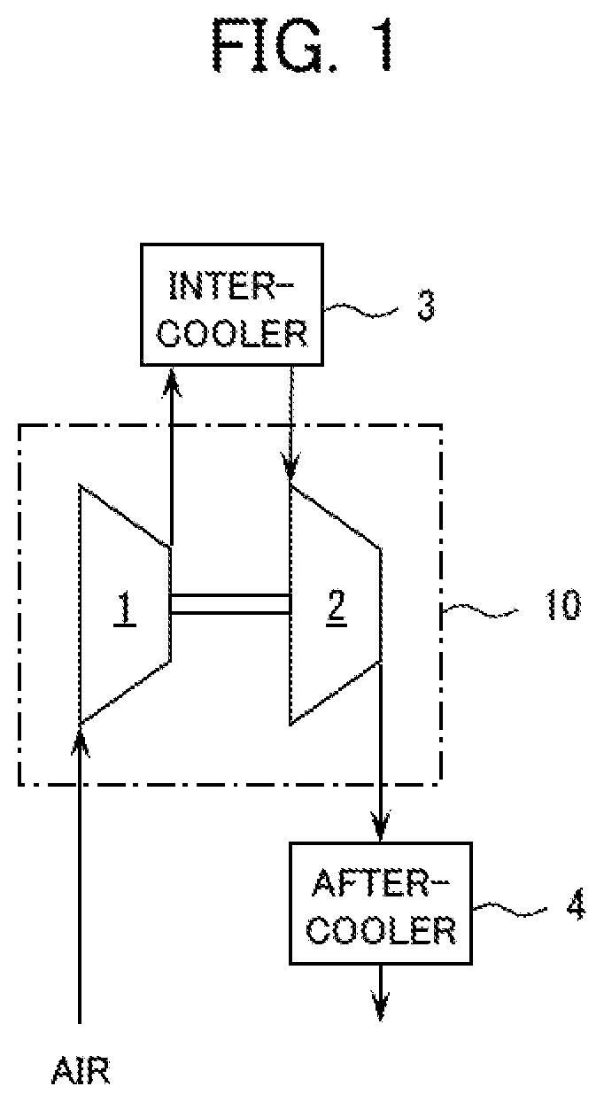
is a schematic diagram depicting the configuration of a two-stage screw compressor according to an embodiment of the present invention.
is a horizontal sectional view depicting the structure of a major part of the two-stage screw compressor according to the embodiment of the present invention.
is a vertical sectional view taken alone section III-III of .
is a radial sectional view taken along section IV-IV of .
is a radial sectional view taken along section V-V of .
is a radial sectional view taken along section VI-VI of .
is a vertical sectional view depicting the structure of a major part of a two-stage screw compressor according to a modification of the present invention.
is a vertical sectional view depicting the structure of a major part of a two-stage screw compressor according to another modification of the present invention.
MODES FOR CARRYING OUT THE INVENTION
An oilless two-stage screw compressor will be described as an example of an embodiment of the present invention, referring to to 6 . Note that in to 6 , illustration of rotors is omitted for convenience' sake.
As depicted in , the two-stage screw compressor of the present embodiment includes a front-stage (low pressure stage) compressing mechanism 1 that compresses air (a gas), an intercooler 3 that cools the compressed air (compressed gas) delivered from the front-stage compressing mechanism 1 , a rear-stage (high pressure stage) compressing mechanism 2 that further compresses the compressed air cooled by the intercooler 3 , and an aftercooler 4 that cools the compressed air delivered from the rear-stage compressing mechanism 2 . The front-stage compressing mechanism 1 and the rear-stage compressing mechanism 2 are integrally configured as a compressor main body 10 .
As illustrated in , the compressor main body 10 includes a front-stage male rotor 11 A and a front-stage female rotor 11 B of the front-stage compressing mechanism 1 , a rear-stage male rotor 12 A and a rear-stage female rotor 12 B of the rear-stage compressing mechanism 2 , and a casing 13 accommodating these components. The casing 13 includes a front-stage intake-side casing 14 , a front-stage main casing 15 , intermediate casings 16 A and 16 B, a rear-stage main casing 17 , and an end cover 18 which are partitioned in the rotor axial direction (the left-right direction in ). The intermediate casings 16 A and 16 B are partitioned in the vertical direction.
The front-stage male rotor 11 A and the rear-stage male rotor 12 A are configured to be coaxial. More specifically, a tooth section 21 A of the front-stage male rotor 11 A has a plurality of (for example, five) teeth extending spirally, and a tooth section 22 A of the rear-stage male rotor 12 A has a plurality of (for example, five) teeth extending spirally. In the present embodiment, the tooth sections 21 A and 22 A are the same in tooth shape and radial size in a radial section. An intermediate shaft section 23 A is connected between the tooth section 21 A of the front-stage male rotor 11 A and the tooth section 22 A of the rear-stage male rotor 12 A, an outside shaft section 24 A is connected to an outer side (the left side in ) of the tooth section 21 A, and an outside shaft 25 A is connected to an outer side (the right side in ) of the tooth section 22 A. The front-stage male rotor 11 A and the rear-stage male rotor 12 A are rotatably supported by only a plurality of bearings 26 A and 27 A which are not disposed between the tooth sections 21 A and 22 A but are disposed on both outer sides of the tooth sections 21 A and 22 A.
Similarly, the front-stage female rotor 11 B and the rear-stage female rotor 12 B are configured to be coaxial. More specifically, a tooth section 21 B of the front-stage female rotor 11 B has a plurality of (for example, seven) teeth extending spirally, and a tooth section 22 B of the rear-stage female rotor 12 B has a plurality of (for example, seven) teeth extending spirally. In the present embodiment, the tooth sections 21 B and 22 B are the same in tooth shape and radial size in a radial section. An intermediate shaft section 23 B is connected between the tooth section 21 B of the front-stage female rotor 11 B and the tooth section 22 B of the rear-stage female rotor 12 B, an outside shaft section 24 B is connected to an outer side (the left side in ) of the tooth section 21 B, and an outside shaft section 25 B is connected to an outer side (the right side in ) of the tooth section 22 B. The front-stage female rotor 11 B and the rear-stage female rotor 12 B are rotatably supported by only a plurality of bearings 26 B and 27 B which are not disposed between the tooth sections 21 B and 22 B but are disposed on both outer sides of the tooth sections 21 B and 22 B.
A tip portion of the outside shaft section 24 A of the front-stage male rotor 11 A projects from a casing 13 , and is provided with a pinion gear 28 . Though not illustrated, the pinion gear 28 is connected to a rotary shaft of a motor through, for example, a gear mechanism and a belt mechanism. With a rotational force of the motor transmitted to the front-stage male rotor 11 A through the pinion gear 28 , the gear mechanism, and the belt mechanism, the front-stage male rotor 11 A and the rear-stage male rotor 12 A are rotated.
The outside shaft section 25 A of the rear-stage male rotor 12 A and the outside shaft section 25 B of the rear-stage female rotor 12 B are provided with timing gears 29 A and 29 B, respectively, and the timing gears 29 A and 29 B are meshed with each other. With a rotational force of the rear-stage male rotor 12 A transmitted to the rear-stage female rotor 12 B through the timing gears 29 A and 29 B, the rear-stage female rotor 12 B and the front-stage female rotor 11 B are rotated. As a result, the tooth section 21 A of the front-stage male rotor 11 A and the tooth section 21 B of the front-stage female rotor 11 B are rotated in such a manner as to be meshed with each other on a non-contact basis, and the tooth section 22 A of the rear-stage male color 12 A and the tooth section 22 B of the rear-stage female rotor 12 B are rotated in such a manner as to be meshed with each other on a non-contact basis.
The casing 13 has a front-stage bore 31 , a front-stage intake flow line 32 , and a front-stage delivery flow line 33 of the front-stage compressing mechanism 1 . The front-stage bore 31 is formed in the main casing 15 , accommodates the tooth section 21 A of the front-stage male rotor 11 A and the tooth section 21 B of the front-stage female rotor 11 B, and forms front-stage operating chambers at tooth grooves of the tooth sections 21 A and 21 B. The front-stage intake flow line 32 is formed in the front-stage intake-side casing 14 and the front-stage main casing 15 , and is a flow line for taking in air into the front-stage operating chambers. The front-stage delivery flow line 33 is a flow line formed in the front-stage main casing 15 and the intermediate casing 16 B, and is a flow line for delivering compressed air from the front-stage operating chambers.
The front-stage operating chamber varies in the internal volume thereof while moving from one side (the left side in ) of the rotor axial direction to the other side (the right side in ). As a result, the front-stage operating chamber sequentially performs an intake step of taking in air from the front-stage intake flow line 32 , a compression step of compressing air, and a delivery step of delivering compressed air to the front-stage delivery flow line 33 .
The front-stage delivery flow line 33 communicates with the front-stage operating chambers in the rotor radial direction, and communicates with the front-stage operating chambers in the rotor axial direction through an axial delivery pocket 34 . The axial delivery pocket 34 is a flow line which is a part of the front-stage delivery flow line 33 , is located so as to overlap with the front-stage bore 31 as viewed in the rotor axial direction, and communicates with the front-stage operating chambers in the rotor axial direction through an axial delivery port 35 (see ).
An air seal 51 A and an oil seal 52 A are provided on an outer circumferential side (specifically, between the front-stage operating chambers and the bearing 26 A) of the outside shaft section 24 A of the front-stage male rotor 11 A. An air seal 51 B and an oil seal 52 B are provided on an outer circumferential side (specifically, between the front-stage operating chambers and the bearing 26 B) of the outside shaft section 24 B of the front-stage female rotor 11 B. The air seals 51 A and 51 B restrain air from leaking out of the front-stage operating chambers, while the oil seals 52 A and 52 B restrain a lubricating oil from leaking from the bearings 26 A and 26 B.
The casing 13 has a rear-stage bore 36 , a rear-stage intake flow line 37 , and a rear-stage delivery flow line 38 of the rear-stage compressing mechanism 2 . The rear-stage bore 36 is formed in the rear-stage main casing 17 , accommodates the tooth section 22 A of the rear-stage male rotor 12 A and the tooth section 22 B of the rear-stage female rotor 12 B, and forms rear-stage operating chambers at tooth grooves of the tool sections 22 A and 22 B. The rear-stage intake flow line 37 is formed in the intermediate casings 16 A and 16 B and the rear-stage main casing 17 , and is a flow line for taking in air into the rear-stage operating chambers. The rear-stage delivery flow line 38 is formed in the rear-stage main casing 17 , and is a flow line for delivering compressed air from the rear-stage operating chambers.
The rear-stage operating chamber varies the internal volume thereof while moving from one side (the left side in ) in the rotor axial direction to the other side (the right side in ). As a result, the rear-stage operating chamber sequentially performs an intake step of taking in air from the rear-stage intake flow line 37 , a compression step of compressing air, and a delivery step of delivering compressed air to the rear-stage delivery flow line 38 .
The rear-stage intake flow line 37 communicates with the rear-stage operating chambers only in the rotor axial direction through an axial intake pocket 39 . The axial intake pocket 39 is a flow line which is a part of the rear-stage intake flow line 37 , is located so as to overlap with the rear-stage bore 36 as viewed in the rotor axial direction, and communicates with the rear-stage operating chambers in the rotor axial direction through an axial intake port 40 (see ).
An air seal 53 A and an oil seal 54 A are provided on an outer circumferential side (specifically, between the rear-stage operating chambers and the bearing 27 A) of the outside shaft section 25 A of the rear-stage male rotor 12 A. An air seal 53 B and an oil seal 54 B are provided on an outer circumferential side (specifically, between the rear-stage operating chambers and the bearing 27 B) of the outside shaft section 25 B of the rear-stage female rotor 12 B. The air seals 53 A and 53 B restrain air from leaking out of the rear-stage operating chambers, while the oil seals 54 A and 54 B restrain a lubricating oil from leaking from the bearings 27 A and 27 B.
Here, as a large characteristic of the present embodiment, the axial delivery pocket 34 of the front-stage compressing mechanism 1 and the axial intake pocket 39 of the rear-stage compressing mechanism 2 are disposed in a positional relation of partly overlapping with each other in the rotor axial direction, as depicted in , and is separated from each other by a separating wall 41 , as depicted in . The rotor circumferential directional position of the separating wall 41 is determined on the basis of the shape of the axial delivery port 35 , the shape of the axial intake port 40 , and the ratio between the delivery flow rate of the front-stage compressing mechanism 1 and the intake flow rate of the rear-stage compressing mechanism 2 .
The shape of the axial delivery port 35 is determined on the basis of the sectional shape of the tooth section 21 A of the front-stage male rotor 11 A and the sectional shape of the tooth section 21 B of the front-stage female rotor 11 B, and the structure of the axial delivery pocket 34 is determined on the basis of the shape of the axial delivery port 35 . In the present embodiment, the axial delivery pocket 34 is formed such that the rotor radial section gradually increases in going in the rotor axial direction (toward the right side in ) from the axial delivery port 35 ; however, the axial delivery pocket 34 may be formed such that the rotor radial section does not vary.
The shape of the axial intake port 40 is determined on the basis of the sectional shape of the tooth section 22 A of the rear-stage male rotor 12 A and the sectional shape of the tooth section 22 B of the rear-stage female rotor 12 B. The structure of the axial intake pocket 39 is determined on the basis of the shape of the axial intake port 40 . In the present embodiment, the axial intake port 40 has a part overlapping with the axial delivery pocket 34 and the separating wall 41 as viewed in the rotor axial direction. Therefore, a part 39 a (see ) of the axial intake pocket 39 corresponding to a part of the axial intake port 40 is shorter in the length in the rotor axial direction than the other parts (see ) of the axial intake pocket 39 corresponding to the other parts of the axial intake port 40 .
In the present embodiment as aforementioned, the axial delivery pocket 34 of the front-stage compressing mechanism 1 and the axial intake pocket 39 of the rear-stage compressing mechanism 2 are arranged in a positional relation of partially overlapping with each other in the rotor axial direction, whereby the intermediate shaft sections 23 A and 23 B can be made shorter, as compared to the case where the pockets 34 and 39 are arranged in a positional relation of not overlapping with each other in the rotor axial direction. Therefore, sag and vibration of the rotors can be restrained. In addition, a reduction in the size of the compressor main body 10 can be realized.
In addition, in the present embodiment, a bearing for supporting the intermediate shaft section 23 A between the tooth section 21 A of the front-stage male rotor 11 A and the tooth section 22 A of the rear-stage male rotor 12 A is eliminated, and a bearing for supporting the intermediate shaft section 23 B between the tooth section 21 B of the front-stage female rotor 11 B and the tooth section 22 B of the rear-stage female rotor 12 B is eliminated, so that bearing loss (mechanical loss) can be reduced. This effect becomes conspicuous in an oilless type compressor, since the oilless type compressor is rotated at high speed for restraining leakage of air from the operating chambers.
Besides, in the present embodiment, the front-stage delivery flow line 33 of the front-stage compressing mechanism 1 communicates with the front-stage operating chambers in the rotor radial direction, and communicates with the front-stage operating chambers in the rotor axial direction through the axial delivery pocket 34 . Therefore, an effect to increase the delivery flow rate and an effect to restrain pressure loss can be obtained. It is to be noted, however, that if a sufficient delivery flow rate can be secured, the front-stage delivery flow line 33 may communicate with the front-stage operating chambers through the axial delivery pocket 34 only in the rotor axial direction.
Note that a case where the rear-stage intake flow line 37 of the rear-stage compressing mechanism 2 communicates with the rear-stage operating chambers through the axial intake pocket 39 only in the rotor axial direction has been taken as an example in describing the aforementioned embodiment, but this is not limitative, and modifications are possible within such a range as not to depart from the gist and technical thought of the present invention. For example, as depicted in , the rear-stage intake flow line 37 may communicate with the rear-stage operating chambers in the rotor radial direction and may communicate with the rear-stage operating chambers in the rotor axial direction through the axial intake pocket 39 . In such a modification, the intake flow rate of the rear-stage compressing mechanism 2 can be increased.
In addition, an oilless (specifically, an oil is not supplied to the front-stage operating chambers and the rear-stage operating chambers) two-stage screw compressor has been taken as an example in describing the aforementioned embodiment, but this is not limitative, and modifications are possible within such a range as not to depart from the gist and technical thought of the present invention. For example, as depicted in , the present invention may be applied to an oil-lubricated (specifically, an oil is supplied to the front-stage operating chambers and the rear-stage operating chambers, whereby an effect to cool the compressed air and the like is obtained) two-stage screw compressor. In such a modification, the timing gears 29 A and 29 B, the air seals 52 A, 51 B, 53 A and 53 B, and the oil seals 52 A, 52 B, 54 A, and 54 B are made unnecessary. In addition, the intercooler 3 may not be provided, unless the temperature of the compressed air delivered from the front-stage compressing mechanism 1 is not sufficiently raised.
Besides, the present invention may be applied, for example, to a three or more-stage screw compressor (namely, a screw compressor including a three or more stage compressing mechanism, in which three or more-stage male rotors are configured to be coaxial, and three or more-stage female rotors are configured to be coaxial). In this case, it is sufficient to apply the characteristics of the present invention to at least two stages of compressing mechanisms.
DESCRIPTION OF REFERENCE CHARACTERS
• 1 : Front-stage compressing mechanism • 2 : Rear-stage compressing mechanism • 3 : Intercooler • 11 A: Front-stage male rotor • 11 B: Front-stage female rotor • 12 A: Rear-stage male rotor • 12 B: Rear-stage female rotor • 21 A, 21 B, 22 A, 22 B: Tooth section • 26 A, 26 B, 27 A, 27 B: Bearing • 31 : Front-stage bore • 33 : Front-stage delivery flow line • 34 : Axial delivery pocket • 36 : Rear-stage bore • 37 : Rear-stage intake flow line • 39 : Axial intake pocket • 41 : Separating wall
Figures (7)
Citations
This patent cites (12)
- US3467300
- US11149732
- US11286933
- US20020081213
- US20170268498
- US20180119601
- US106704179
- US206636781
- US62-168987
- US62-183091
- US63-36086
- US2017-166401