Pool Cleaner with Releasable Brush Assembly
Abstract
A pool cleaner equipped with a rotating brush assembly is disclosed. The brush assembly is removably coupled to the pool cleaner using clamps that are readily accessible, supported by the pool cleaner, and operable by hand. The clamps may be manipulated between a ready configuration, a loaded configuration to receive a brush assembly, and a locked configuration to secure the brush assembly.
Claims (16)
1. A pool cleaner configured to clean a pool, the pool cleaner comprising: a housing; a driving assembly; a transmission assembly operably coupled to the driving assembly, the transmission assembly including a brush gear; at least one traction assembly operably coupled to the transmission assembly and configured to convey the housing across the pool; a mounting rod coupled to the brush gear; a clamp supported on the mounting rod; and a brush assembly removably coupled to the housing; wherein the pool cleaner has: a ready configuration in which the mounting rod is exposed through the clamp and configured to receive the brush assembly; a loaded configuration in which the brush assembly is positioned against the mounting rod; and a locked configuration in which the clamp holds the brush assembly against the mounting rod such that rotation of the brush gear is transferred to the brush assembly via the mounting rod.
13. A pool cleaner configured to clean a pool, the pool cleaner comprising: a housing having a foot; a driving assembly; a transmission assembly operably coupled to the driving assembly, the transmission assembly including a brush gear; at least one traction assembly operably coupled to the transmission assembly and configured to convey the housing across the pool; a brush assembly; a mounting rod supported by the foot of the housing, the mounting rod extending outward to engage the brush gear and inward to support the brush assembly; a clamp rotatable between a first configuration in which the brush assembly is movable relative to the mounting rod and a second configuration in which the brush assembly is secured to the mounting rod such that rotation of the brush gear is transferred to the brush assembly via the mounting rod.
Show 14 dependent claims
2. The pool cleaner of claim 1 , wherein an outer end of the mounting rod is keyed to the brush gear or integrally formed with the brush gear.
3. The pool cleaner of claim 1 , wherein: the mounting rod includes a flat connection surface with a positioning slot; the brush assembly includes a flat connection surface with a positioning rod; and in the loaded and locked configurations, the flat connection surface of the mounting rod contacts the flat connection surface of the brush assembly, and the positioning slot of the mounting rod receives the positioning rod of the brush assembly.
4. The pool cleaner of claim 1 , wherein: the mounting rod includes a rounded connection surface; the brush assembly includes a rounded connection surface; and in the loaded and locked configurations, the rounded connection surfaces cooperate to mate with the clamp.
5. The pool cleaner of claim 1 , wherein: the clamp includes a hollow body with a notch sized to receive a connection post at an end of the brush assembly; in the ready configuration, the mounting rod is exposed through the notch in the clamp; and in the loaded configuration, the connection post of the brush assembly has passed through the notch and into contact with the mounting rod.
6. The pool cleaner of claim 5 , wherein, in the locked configuration, the clamp inhibits removal of the connection post through the notch.
7. The pool cleaner of claim 1 , wherein the clamp is rotated about the mounting rod from the loaded configuration to the locked configuration.
8. The pool cleaner of claim 1 , wherein: the clamp includes a hollow body with a groove; the brush assembly includes a rib; in the loaded configuration, the rib is disengaged from the clamp; and in the locked configuration, the rib is captured in the groove of the clamp.
9. The pool cleaner of claim 8 , wherein: the groove of the clamp includes at least one positioning recess; and the rib of the brush assembly includes at least one positioning bump sized for receipt in the at least one positioning recess in the locked configuration.
10. The pool cleaner of claim 1 , wherein the clamp includes a plate with a through-hole, the mounting rod extending through the through-hole to the brush gear.
11. The pool cleaner of claim 10 , wherein the housing includes a foot that supports the mounting rod, wherein the plate of the clamp is located inward of the foot.
12. The pool cleaner of claim 1 , wherein the clamp is a first clamp configured to receive a first end of the brush assembly, the pool cleaner further comprising a second clamp configured to receive a second end of the brush assembly.
14. The pool cleaner of claim 13 , wherein the clamp is supported on the mounting rod at a location inward of the foot.
15. The pool cleaner of claim 13 , wherein the brush assembly and the clamp rotate about the same axis.
16. The pool cleaner of claim 13 , wherein the clamp is captured between the foot on one side and a raised stop ring of the mounting rod on the other side.
Full Description
Show full text →
CROSS REFERENCE TO RELATED APPLICATION
This application is a national stage application of Internation Application No. PCT/IB2020/054860 filed May 21, 2020, which claims priority to Chinese Application Serial No. 201920735173.6 filed May 21, 2019, the disclosures of which are hereby expressly incorporated by reference herein in their entirety.
FIELD OF THE DISCLOSURE
The present invention relates to the field of pool cleaners, and in particular to a pool cleaner having a releasable brush assembly, and to methods of using the same.
BACKGROUND OF THE DISCLOSURE
A pool cleaner may be equipped with a rotating brush. When the pool cleaner is in use, an actuating mechanism of the pool cleaner drives the pool cleaner, causing the pool cleaner to move across the floor and/or sidewalls of the pool. At the same time, the actuating mechanism drives rotation of the brush through a transmission gear set, so that the wheel brush cleans debris from the floor and/or sidewalls of the pool. The rotating brush may become worn as it rubs against the pool and may require frequent replacement. However, current replacement options are cumbersome and time consuming.
SUMMARY
The present disclosure provides a pool cleaner equipped with a rotating brush assembly. The brush assembly is removably coupled to the pool cleaner using clamps that are accessible, supported by the pool cleaner, and operable by hand. The clamps may be manipulated between a ready configuration, a loaded configuration to receive a brush assembly, and a locked configuration to secure the brush assembly.
According to an exemplary embodiment of the present disclosure, a pool cleaner configured to clean a pool is disclosed, the pool cleaner including a housing, a driving assembly, a transmission assembly operably coupled to the driving assembly, the transmission assembly including a brush gear, at least one traction assembly operably coupled to the transmission assembly and configured to convey the housing across the pool, a mounting rod coupled to the brush gear, a clamp supported on the mounting rod, and a brush assembly removably coupled to the housing. The pool cleaner has a ready configuration in which the mounting rod is exposed through the clamp and configured to receive the brush assembly, a loaded configuration in which the brush assembly is positioned against the mounting rod, and a locked configuration in which the clamp holds the brush assembly against the mounting rod such that rotation of the brush gear is transferred to the brush assembly via the mounting rod.
In certain embodiments, an outer end of the mounting rod is keyed to the brush gear or integrally formed with the brush gear.
In certain embodiments, the mounting rod includes a flat connection surface with a positioning slot and the brush assembly includes a flat connection surface with a positioning rod. In the loaded and locked configurations, the flat connection surface of the mounting rod contacts the flat connection surface of the brush assembly, and the positioning slot of the mounting rod receives the positioning rod of the brush assembly.
In certain embodiments, the mounting rod includes a rounded connection surface and the brush assembly includes a rounded connection surface. In the loaded and locked configurations, the rounded connection surfaces cooperate to mate with the clamp.
In certain embodiments, the clamp includes a hollow body with a notch sized to receive a connection post at an end of the brush assembly. In the ready configuration, the mounting rod is exposed through the notch in the clamp. In the loaded configuration, the connection post of the brush assembly has passed through the notch and into contact with the mounting rod.
In certain embodiments, the clamp inhibits removal of the connection post through the notch in the locked configuration.
In certain embodiments, the clamp is rotated about the mounting rod from the loaded configuration to the locked configuration.
In certain embodiments, the clamp includes a hollow body with a groove and the brush assembly includes a rib. In the loaded configuration, the rib is disengaged from the clamp. In the locked configuration, the rib is captured in the groove of the clamp. The groove of the clamp may include at least one positioning recess, and the rib of the brush assembly may include at least one positioning bump sized for receipt in the at least one positioning recess in the locked configuration.
In certain embodiments, the clamp includes a plate with a through-hole, the mounting rod extending through the through-hole to the brush gear. The housing may include a foot that supports the mounting rod, wherein the plate of the clamp is located inward of the foot.
In certain embodiments, the clamp is a first clamp configured to receive a first end of the brush assembly, the pool cleaner further comprising a second clamp configured to receive a second end of the brush assembly.
According to another exemplary embodiment of the present disclosure, a pool cleaner configured to clean a pool is disclosed, the pool cleaner including a housing having a foot, a driving assembly, a transmission assembly operably coupled to the driving assembly, the transmission assembly including a brush gear, at least one traction assembly operably coupled to the transmission assembly and configured to convey the housing, across the pool, a brush assembly, a mounting rod supported by the foot of the housing, the mounting rod extending outward to engage the brush gear and inward to support the brush assembly, a clamp rotatable between a first configuration in which the brush assembly is movable relative to the mounting rod and a second configuration in which the brush assembly is secured to the mounting rod such that rotation of the brush gear is transferred to the brush assembly via the mounting rod.
In certain embodiments, the clamp is supported on the mounting rod at a location inward of the foot.
In certain embodiments, the brush assembly and the clamp rotate about the same axis.
In certain embodiments, the clamp is captured between the foot on one side and a raised stop ring of the mounting rod on the other side.
According to yet another exemplary embodiment of the present disclosure, a method of using a pool cleaner is disclosed including the steps of inserting a brush assembly into a clamp and into contact with a mounting rod, rotating the clamp to secure the brush assembly against the mounting rod, and operating a driving assembly to rotate at least one traction mechanism, the mounting rod, and the brush assembly via the mounting rod.
In certain embodiments, the inserting step comprises inserting a positioning rod of the brush assembly into a positioning slot of the mounting rod.
In certain embodiments, the rotating step comprises capturing a rib of the brush assembly in a groove of the clamp.
In certain embodiments, the method further includes rotating the clamp in an opposite direction, separating the brush assembly from the mounting rod, and replacing the brush assembly with a new brush assembly.
BRIEF DESCRIPTION OF THE DRAWINGS
The above-mentioned and other features and advantages of this disclosure, and the manner of attaining them, will become more apparent and be better understood by reference to the following description of embodiments of the invention taken in conjunction with the accompanying drawings, wherein:
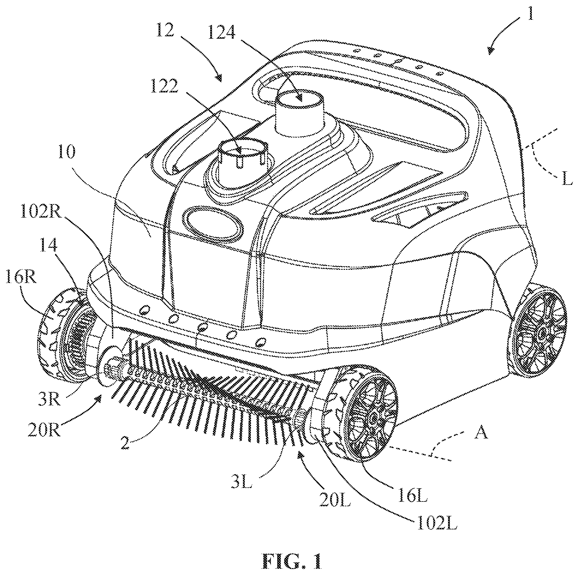
is a perspective view of a pool cleaner including an exemplary brush assembly of the present disclosure;
is a first perspective view of the brush assembly showing a first side of the brush assembly;
is a second perspective view of the brush assembly showing a second side of the brush assembly;
is a perspective view of an exemplary clamp of the present disclosure;
is a perspective view of an exemplary mounting rod of the present disclosure;
is a perspective view of an exemplary brush gear of the present disclosure;
is a perspective view of the clamp, the mounting rod, and the brush gear in a ready configuration;
is a schematic axial view of the ready configuration of ;
is a perspective view of the clamp, the mounting rod, the brush gear, and the brush assembly in a loaded configuration;
is a schematic axial view of the loaded configuration of ;
is a perspective view of the clamp, the mounting rod, the brush gear, and the brush assembly in a locked configuration; and
is a schematic axial view of the locked configuration of .
Corresponding reference characters indicate corresponding parts throughout the several views. The exemplifications set out herein illustrate exemplary embodiments of the invention and such exemplifications are not to be construed as limiting the scope of the invention in any manner.
DETAILED DESCRIPTION
provides a pool cleaner 1 configured to clean a floor and/or sidewalls of a pool. The pool cleaner 1 includes a housing 10 having a longitudinal axis L and front feet 102 R, L. The pool cleaner 10 also includes a hydraulic driving assembly 12 including a water inlet 122 , a water outlet 124 , and an impeller (not shown) disposed within the housing 10 and in fluid communication between the water inlet 122 and the water outlet 124 . The pool cleaner 1 also includes a filtration assembly (not shown) disposed within the housing 10 to collect debris. The pool cleaner 1 further includes a transmission assembly 14 operably coupled to the driving assembly 12 and including a plurality of gears, including brush gears (shown elsewhere). The pool cleaner 1 further includes one or more traction assemblies, illustratively two right wheels 16 R and two left wheels 16 L, operably coupled to the transmission assembly 14 .
The pool cleaner 1 also includes at least one rotating brush assembly 2 having opposing right and left ends 20 R, 20 L removably coupled to the housing 10 using right and left clamps 3 R, 3 L, respectively. Advantageously, the clamps 3 R, 3 L are readily accessible, are supported by the pool cleaner 1 (i.e., are not detachable), and are operable by hand without the use of additional tools. These clamps 3 R, 3 L are described in detail below. In , the brush assembly 2 extends laterally across a front end of the housing 10 between feet 102 R, 102 L, along an axis A that is perpendicular to the longitudinal axis 1 , of the housing 10 , but this position may vary. It is also within the scope of the present disclosure for the pool cleaner 1 to include more than one brush assembly 2 , such as a second brush assembly (not shown) that extends laterally across a rear end of the housing 10 .
In operation, water travels through the water inlet 122 , across the impeller, and out of the water outlet 124 , which rotates the impeller. The impeller's rotation is transferred to the wheels 16 R, 16 L via the transmission assembly 14 , which causes the pool cleaner 1 to drive across the pool. The impeller's rotation is also transferred to the brush assembly 2 via the transmission assembly 14 , which causes the brush assembly 2 to rotate about the axis A to clear debris from the pool.
The brush assembly 2 is shown in . The brush assembly 2 includes a shaft 22 that extends along the rotation axis A and a plurality of bristles 24 extending radially outward from the shaft 22 . At each end 20 R, 20 L, brush assembly 2 includes a connection arm 21 R, 21 L, which may be integrally formed with shaft 22 or otherwise attached to shaft 22 (e.g., welded, adhered, fastened). Each connection arm 21 R, 21 L has a flat connection surface 211 R, 211 L on one side ( ) and a rounded connection surface 212 R, 212 L on the opposing side ( ). A positioning pin 2111 R, 2111 L extends radially outward from each flat connection surface 211 R, 211 L ( ). A limiting rib 213 R, 213 L extends radially outward from each rounded connection surface 212 R, 212 L, with one or more positioning, bumps 2131 R, 2131 L centrally located on each limiting rib 213 R, 213 L.
The right clamp 3 R is shown in . The following description is written in terms of the right clamp 3 R, but it is understood that this description may also apply to the left clamp 3 L, which may be a mirror image of the right clamp 3 R. The right clamp 3 R includes an inner hollow body 31 R coupled to an outer fixing plate 32 R. The hollow body 31 R may be knurled or otherwise textured to facilitate gripping by a user. The hollow body 31 R is interrupted by a notch 311 R such that the hollow body 31 R is arc-shaped (e.g., C-shaped) with a radian greater than 90° and less than 180°. A circumferential limiting groove 312 R extends from the notch 311 R and through a central portion of the hollow body 31 R, with one or more positioning recesses 3121 R centrally located in the limiting groove 312 R. A limiting step 313 R extends radially inward from the hollow body 31 R adjacent to the fixing plate 32 R. A through-hole 321 R extends through the fixing plate 32 R and communicates with the hollow interior of the body 31 R.
A right mounting rod 4 R (which may also be referred to herein as a torsion rod) is shown in . The following description is written in terms of the right mounting rod 4 R, but it is understood that this description may also apply to the left mounting rod (not shown), which may be a mirror image of the right mounting rod 4 R. The right mounting rod 4 R includes an inner connection post 41 R, an intermediate body 42 R having a stop ring 422 R that extends radially outward from the intermediate body 42 R, and an outer driven end 43 R having a hexagonal profile, although this profile may vary. The connection post 41 R has a flat connection surface 411 R on one side and a rounded connection surface 412 R on the opposing side. The flat connection surface 411 R or the connection post 41 R includes a positioning slot 4111 R.
A right brush gear 142 R is shown in . The following description is written in terms of the right brush gear 142 R, but it is understood that this description may also apply to the left brush gear (not shown), which may be a mirror image of the right brush gear 142 R. The right brush gear 142 R includes outer gear teeth 144 R configured to mesh with other gears of the transmission assembly 14 ( ). The right brush gear 142 R also includes a driving end formed by an internal notch 146 R having a hexagonal shape, although this shape may vary.
The right brush gear 142 R, the right mounting rod 4 R, and the right clamp 3 R are shown together in . The right mounting rod 4 R is rotatably supported by the right foot 102 R of the housing 10 ( ), with the right brush gear 142 R located outward relative to the foot 102 R (i.e., further from the longitudinal axis L of ) and the right clamp 3 R located inward relative to the foot 102 R (i.e., closer to the longitudinal axis L of ).
Outward from (or concealed within) the foot 102 R, the right brush gear 142 R is coupled to the right mounting rod 4 R, such that rotation of the right brush gear 142 R is transferred to the right mounting rod 4 R. In , the hexagonal driving end 146 R of the right brush gear 142 R receives the hexagonal driven end 43 R of the right mounting rod 4 R in a keyed manner. As noted above, these hexagonal profiles may vary. It is also within the scope of the present disclosure for the right brush gear 142 R and the right mounting rod 4 R to be integrally formed together or otherwise attached together (e.g., welded, adhered, fastened).
Inward of the foot 102 R, the right clamp 3 R is supported on the right mounting rod 4 R. In , the hollow body 31 R of the right clamp 3 R receives the connection post 41 R of the right mounting rod 4 R, and the fixing plate 32 R of the right clamp 3 R is supported on the intermediate body 42 R ( ) of the right mounting rod 4 R. In this position, the stop ring 422 R of the right mounting rod 4 R abuts the limiting step 313 R of the right clamp 3 R ( ) to retain the right clamp 3 R on the right mounting rod 4 R. Thus, the right clamp 3 R is retained between the foot 102 R on the outside and the stop ring 422 R on the inside. The driven end 43 R of the right mounting rod 4 R extends outwardly through the through-hole 321 R ( ) in the fixing plate 32 R and through the right foot 102 R to mate with the right brush gear 142 R, as described above.
The insertion of a new brush assembly 2 will now be described with reference to .
The components are shown in a ready configuration in . In this ready configuration, the hollow body 31 R of the right clamp 3 R and/or the connection post 41 R of the right mounting rod 4 R have been rotated such that the flat connection surface 411 R and the positioning slot 4111 R of the right mounting rod 4 R are aligned with the notch 311 R in the right clamp 3 R. In other words, the positioning slot 4111 R is visible and accessible through the notch 311 R. Such rotation may be achieved by gripping and rotating the textured hollow body 31 R.
The components are shown in a loaded configuration in , with the brush assembly 2 coupled to the right mounting rod 4 R. In this loaded configuration, the connection arm 21 R of the brush assembly 2 has been inserted radially through the notch 311 R and into the hollow body 31 R of the right clamp 3 R in a radial direction 500 . The radial extent of the notch 311 R may be sufficiently large to receive the connection arm 21 R. The flat connection surface 211 R of the brush assembly 2 abuts the flat connection surface 411 R of the right mounting rod 4 R, with the positioning pin 2111 R of the brush assembly 2 extending radially into the positioning slot 4111 R of the right mounting rod 4 R, thereby inhibiting axial movement of the brush assembly 2 relative to the right mounting rod 4 R. It is within the scope of the present disclosure to reverse the placement of the positioning pin 2111 R and the positioning slot 4111 R, such that the positioning pin 2111 R is instead located on the right mounting rod 4 R and the positioning slot 4111 R is instead located on the brush assembly 2 .
The components are shown in a locked configuration in , with the brush assembly 2 further coupled to the right clamp 3 R. In this locked configuration, the hollow body 31 R of the right clamp 3 R has been rotated in a direction 502 (e.g., upward) to capture the limiting rib 213 R of the brush assembly 2 within the limiting groove 312 R of the right clamp 3 R, thereby inhibiting both radial and axial movement of the brush assembly 2 relative to the right clamp 3 R. Such rotation may be achieved by gripping and rotating the textured hollow body 31 R. This locked configuration may be retained by forcing the positioning bumps 2131 R of the limiting rib 213 R into corresponding positioning recesses 3121 R of the limiting groove 312 R, which act as detent mechanisms to inhibit further rotation of the right clamp 3 R.
As shown in , the locked configuration captures the connection arm 21 R of the brush assembly 2 and the connection post 41 R of the right mounting rod 4 R within the hollow body 31 R of the right clamp 3 R. With the flat connection surface 211 R of the connection arm 21 R abutting the flat connection surface 411 R of the connection post 41 R, the rounded connection surface 212 R of the connection arm 21 R and the rounded connection surface 412 R of the connection post 41 R ( ) cooperate to define a generally cylindrical outer profile that fits within the generally cylindrical hollow body 31 R. The outer diameter of the connection arm 21 R and the connection post 41 R. (measured between the rounded connection surfaces 212 R, 412 R) may be equal to or slightly larger than the inner diameter of the cylindrical hollow body 31 R to facilitate close contact between the components. In this way, the hollow body 31 R clamps the connection arm 21 R and the connection post 41 R together and firmly retains the positioning pin 2111 R in the positioning slot 4111 R. It is understood that the connection arm 21 R, the hollow body 31 R, and the connection post 41 R may vary in shape while ensuring this clamped connection.
With the brush assembly 2 in the locked configuration, the pool cleaner 1 of may be operated to clean the pool. As noted above, this operation involves rotating the impeller (not shown) and various gears of the transmission assembly 14 , including the right brush gear 142 R that interacts with the right end 20 R of the brush assembly 2 in . The rotation of the right brush gear 142 R is transferred to the right mounting rod 4 R via the keyed connection therebetween, as described above. Then, the rotation of the right mounting rod 4 R is transferred to the connection arm 21 R of the brush assembly 2 via the clamped connection therebetween, as described above. The left end 201 of the brush assembly 2 ( ) may be rotated in a similar manner.
The brush assembly 2 may become worn over time. The worn brush assembly 2 may be removed by reversing the above-described insertion process. First, the worn brush assembly 2 may be unlocked by moving the components from the locked configuration of to the loaded configuration of . This unlocking step may involve rotating the hollow body 31 R of the right clamp 3 R opposite the direction 502 (i.e., downward) to free the limiting rib 213 R of the connection arm 21 R from the limiting groove 312 R of the right clamp 3 R. Then, the brush assembly 2 may be removed by moving the components from the loaded configuration of to the ready configuration of . This removing step may involve pulling the connection arm 21 R through the exposed notch 311 R of the hollow body 31 R opposite the direction 500 , which also frees the positioning pin 2111 R of the connection arm 21 R from the positioning slot 4111 R of the connection post 41 R. With the components in the ready configuration, the insertion process may be repeated with a fresh, replacement brush assembly 2 .
While this invention has been described as having exemplary designs, the present invention can be further modified within the spirit and scope of this disclosure. This application is therefore intended to cover any variations, uses, or adaptations of the invention using its general principles. Further, this application is intended to cover such departures from the present disclosure as come within known or customary practice in the art to which this invention pertains and which fall within the limits of the appended claims.
Figures (12)
Citations
This patent cites (100)
- US3430277
- US3822754
- US3950809
- US4962559
- US5001800
- US5245723
- US5317776
- US5351355
- US5454129
- US5507058
- US5569371
- US5768734
- US5896610
- US6099658
- US6155657
- US6212725
- US6248232
- US6299699
- US6448494
- US6564417
- US6742613
- US6797157
- US6939460
- US6954960
- US6971136
- US7060182
- US7117554
- US7178188
- US7328473
- US7437790
- US7520015
- US7636975
- US7849547
- US8128815
- US8141191
- US8225446
- US8261759
- US8281441
- US8296891
- US8307485
- US8341789
- US8424142
- US8434182
- US8505143
- US8623201
- US8661594
- US8800088
- US8869337
- US9021645
- US9119463
- US9677294
- US10494829
- US20030101523
- US20040168838
- US20050108836
- US20050247613
- US20060048312
- US20060059637
- US20060064825
- US20060265820
- US20070107148
- US20080141471
- US20080169247
- US20080244842
- US20110000030
- US20120102665
- US20140137343
- US20140259464
- US20140273541
- US20150101135
- US20150121636
- US20150267431
- US20160145884
- US20160215516
- US20180127999
- US20180163422
- US20180172114
- US20180328059
- US20190058286
- US20190203490
- US20200150679
- US20200256076
- US20210131805
- US3031667
- US103835536
- US103867000
- US205065124
- US207277924
- US207526181
- US208152635
- US208380174
- US109723251
- US210106835
- US210239260
- US210239261
- US2735437
- US2015331
- US97156
- US2004/097145
- USWO-2019058286