Vehicle Configuration with Aerodynamic Shaping to Reduce Drag, and Vehicle and Method for the Same
Abstract
There is provided a vehicle configuration to reduce drag in a fluid stream. The vehicle configuration has a vehicle body. The vehicle configuration further has at least one auxiliary body coupled to, and positioned a distance from, the vehicle body, to form a channel between the at least one auxiliary body and the vehicle body. The vehicle configuration further has one or more exterior profiles of one or more of, the vehicle body and the at least one auxiliary body. The one or more exterior profiles are positioned in proximity to the channel, and are shaped with an aerodynamic shaping, so that the one or more exterior profiles each comprises one or more concave shape portions. When a fluid flow from the fluid stream flows through the channel, the drag resulting from fluid flow interactions between the vehicle body and the at least one auxiliary body is reduced.
Claims (20)
1. A vehicle configuration to reduce drag in a fluid stream, the vehicle configuration comprising: a vehicle body; at least one auxiliary body coupled to, and positioned a distance from, the vehicle body, to form a gap between a lower surface of the at least one auxiliary body and an upper surface of the vehicle body; and one or more carved out exterior profiles of one or more of, the upper surface of the vehicle body, and the lower surface of the at least one auxiliary body, the one or more carved out exterior profiles positioned in proximity to the gap, and externally shaped with an aerodynamic shaping to carve out the one or more carved out exterior profiles and to reduce a strength of a shock wave in the gap, so that the one or more carved out exterior profiles each comprises two or more concave shape portions alternating, in series, in opposite concavities, wherein when a fluid flow from the fluid stream flows through the gap, the drag resulting from fluid flow interactions between the vehicle body and the at least one auxiliary body is reduced, the fluid flow comprising a compressible fluid flow moving at one of, transonic speed, subsonic speed, or supersonic speed, and the drag comprising interference drag, and the aerodynamic shaping based on a Mach number of the fluid flow.
12. A vehicle comprising: a vehicle configuration to reduce drag in an air stream, the vehicle configuration comprising: a vehicle body; at least one auxiliary body coupled to, and positioned a distance from the vehicle body, to form a gap between a lower surface of the at least one auxiliary body and an upper surface of the vehicle body, wherein an air flow from the air stream comprises a compressible air flow moving at one of, transonic speed, subsonic speed, or supersonic speed, through the gap; and one or more carved out exterior profiles of one or more of, the upper surface of the vehicle body, and the lower surface of the at least one auxiliary body, the one or more carved out exterior profiles positioned in proximity to the gap, and externally shaped with an aerodynamic shaping to carve out the one or more carved out exterior profiles and to reduce a strength of a shock wave in the gap, so that the one or more carved out exterior profiles each comprises two or more concave shape portions alternating, in series, in opposite concavities, wherein when the air flow from the air stream flows through the gap, the drag resulting from air flow interactions between the vehicle body and the at least one auxiliary body is reduced, the air flow comprising a compressible air flow moving at one of, transonic speed, subsonic speed, or supersonic speed, and the drag comprising interference drag, and the aerodynamic shaping based on a Mach number of the air flow.
16. A method to reduce drag of a vehicle in a fluid stream, the method comprising: providing a vehicle configuration for the vehicle, the vehicle configuration comprising: a vehicle body; at least one auxiliary body coupled to, and positioned a distance from, the vehicle body, to form a gap between a lower surface of the at least one auxiliary body and an upper surface of the vehicle body; and one or more carved out exterior profiles of one or more of, the upper surface of the vehicle body, and the lower surface of the at least one auxiliary body, the one or more carved out exterior profiles positioned in proximity to the gap; externally shaping the one or more carved out exterior profiles with an aerodynamic shaping to carve out the one or more carved out exterior profiles and to reduce a strength of a shock wave in the gap, so that the one or more carved out exterior profiles each comprises two or more concave shape portions alternating, in series, in opposite concavities, and the one or more carved out exterior profiles comprise one or more of, a longitudinal contour with a longitudinal concavity, and a lateral contour with a lateral concavity; and reducing, with the vehicle configuration having the one or more carved out exterior profiles shaped with the aerodynamic shaping, the drag resulting from fluid flow interactions between the vehicle body and the at least one auxiliary body, when a fluid flow from the fluid stream flows through the gap, the fluid flow comprising a compressible fluid flow moving at one of, transonic speed, subsonic speed, or supersonic speed, and the drag comprising interference drag, and the aerodynamic shaping based on a Mach number of the fluid flow.
Show 17 dependent claims
2. The vehicle configuration of claim 1 , wherein the at least one auxiliary body is in structural communication with the vehicle body.
3. The vehicle configuration of claim 1 , wherein the at least one auxiliary body comprises a nacelle, and the nacelle is in structural communication, via a pylon, with the vehicle body, and further wherein, the pylon has an outboard exterior profile and an inboard exterior profile, and one or more of, the outboard exterior profile, and the inboard exterior profile, are shaped with the aerodynamic shaping.
4. The vehicle configuration of claim 1 , wherein the one or more carved out exterior profiles of the upper surface of the vehicle body are shaped aft of the at least one auxiliary body with the aerodynamic shaping, to reduce aft recirculation zones of separated fluid flow formed aft of the at least one auxiliary body.
5. The vehicle configuration of claim 1 , wherein the one or more carved out exterior profiles comprise one or more of, a longitudinal contour with a longitudinal concavity, and a lateral contour with a lateral concavity.
6. The vehicle configuration of claim 1 , wherein a threshold distance of the gap between the upper surface of the vehicle and the lower surface of the at least one auxiliary body is determined depending on a vehicle flight speed, the Mach number of the fluid flow, a Reynolds number, a length of the vehicle ahead of the auxiliary body, a vehicle boundary layer height at a start of the gap, and a vehicle angle of attack.
7. The vehicle configuration of claim 1 , wherein the interference drag, including comprises compressibility drag.
8. The vehicle configuration of claim 1 , wherein the at least one auxiliary body comprises a nacelle, an engine nacelle, a fuel tank, a pod, a sensor pod, a booster, or a missile.
9. The vehicle configuration of claim 8 , wherein the at least one auxiliary body comprises the nacelle, and the nacelle is suspended at one of, above the vehicle body, or below the vehicle body.
10. The vehicle configuration of claim 1 , wherein the comprise one or more concave-up portions and one or more concave-down portions.
11. The vehicle configuration of claim 10 , wherein longitudinal spacing of curvature inflection points indicating where a concavity is reversed from each of the one or more concave-up portions to each of the one or more concave-down portions longitudinally along the one or more carved out exterior profiles depends on contours and the Mach number of an upstream air flow.
13. The vehicle of claim 12 , wherein the vehicle comprises a blended wing body aircraft, a commercial aircraft, a military aircraft, a launch vehicle, a rocket-propelled vehicle, or a spacecraft.
14. The vehicle of claim 12 , wherein the at least one auxiliary body comprises a nacelle, an engine nacelle, a fuel tank, a pod, a sensor pod, a booster, or a missile.
15. The vehicle of claim 12 , wherein the at least one auxiliary body is in structural communication, via a pylon, with the vehicle body, and the pylon has an outboard exterior profile and an inboard exterior profile, wherein one or more of, the outboard exterior profile, and the inboard exterior profile, are shaped with the aerodynamic shaping.
17. The method of claim 16 , wherein providing the vehicle configuration further comprises, providing the vehicle configuration wherein the at least one auxiliary body is in structural communication, via a pylon, with the vehicle body, and the pylon has an outboard exterior profile and an inboard exterior profile, wherein one or more of, the outboard exterior profile, and the inboard exterior profile, are shaped with the aerodynamic shaping.
18. The method of claim 16 , wherein shaping the one or more carved out exterior profiles, further comprises, initializing the shaping of the carved out exterior profile of the upper surface of the vehicle body, by carving a contoured profile of the lower surface of the at least one auxiliary body into the upper surface of the vehicle body, to obtain an initial shape optimized vehicle body.
19. The method of claim 16 , wherein shaping the one or more carved out exterior profiles, further comprises, modeling the vehicle configuration, to obtain a three-dimensional model, and optimizing the three-dimensional model using an optimization approach, to obtain an optimized fluid flow through the gap.
20. The method of claim 16 , wherein shaping the one or more carved out exterior profiles, further comprises, shaping the carved out exterior profile of the one or more carved out exterior profiles of a vehicle body aft surface of the vehicle body, to reduce aft recirculation zones of separated fluid flow formed aft of the at least one auxiliary body.
Full Description
Show full text →
FIELD
The disclosure relates generally to design configurations for vehicles, and relates more particularly, to vehicle design configurations with aerodynamic shaping for air vehicles, such as blended wing body (BWB) aircraft and other air vehicles, to reduce drag, the occurrence of shocks or shock waves, and the occurrence of aft recirculation and structural fatigue.
BACKGROUND
In certain air vehicles, such as blended wing body (BWB) aircraft, launch vehicles, military or commercial aircraft, or other air vehicles, various auxiliary bodies, such as nacelles, for example, engine nacelles, or fuel tanks, pods, boosters, missiles, or other auxiliary bodies may be top-mounted, bottom-mounted, or side-mounted on a vehicle body, including a fuselage or wings. A channel or gap may be created between a lower surface of the top-mounted, bottom-mounted, or side-mounted auxiliary body and an upper surface, or outer surface, of the vehicle body facing the lower surface. Under certain operating conditions of the air vehicle, for example, flying at transonic, subsonic, or supersonic speeds or velocities, air flow interactions between the auxiliary body and the vehicle body may create shock waves or shocks within the channel that generate drag, for example, interference drag, and may further result in aft recirculation and aft recirculation zones, or separated air, formed in an exhaust air stream. Increased interference drag and increased aft recirculation may lead to decreased aerodynamic performance and a lower flight efficiency of the air vehicle.
One known design solution for military, commercial, and/or BWB aircraft to avoid interference drag involves removing the channel or gap between a top-mounted engine nacelle and a vehicle body, for example, embedding a lower portion of the engine nacelle into a top surface of the vehicle body, to create a boundary layer ingestion design, where the top surface of the vehicle body is an internal mold line for air flow entering an engine inlet. However, with the boundary layer ingestion design, low velocity boundary layer air may be ingested by the engine inlet, which may result in lower thrust. Moreover, with the boundary layer ingestion design, a mixture of low velocity boundary layer air and high velocity free stream air may be ingested by the engine inlet, which may result in a non-uniform flow pattern at the engine fan face that may affect engine performance and may result in increased fuel consumption and structural fatigue.
Accordingly, there is a need for a vehicle configuration and method that do not remove the channel or gap between the auxiliary body and the vehicle body, while still reducing drag in the channel or gap, during flight at transonic, subsonic, or supersonic speeds or velocities, that reduce the occurrence of shocks or shock waves and aft recirculation, or separated air, in an exhaust air stream, that increase aerodynamic performance and flight efficiency of the air vehicle, and that provide additional advantages over known vehicle configurations and methods.
SUMMARY
Example implementations of the present disclosure provide a vehicle configuration and a method for reducing drag and aft recirculation. As discussed in the below detailed description, versions of the vehicle configuration and method may provide significant advantages over known vehicle configurations and methods.
In a version of the disclosure, there is provided a vehicle configuration to reduce drag in a fluid stream. The vehicle configuration comprises a vehicle body. The vehicle configuration further comprises at least one auxiliary body coupled to, and positioned a distance from, the vehicle body, to form a channel between the at least one auxiliary body and the vehicle body.
The vehicle configuration further comprises one or more exterior profiles of one or more of, the vehicle body, and the at least one auxiliary body. The one or more exterior profiles are positioned in proximity to the channel, and are shaped with an aerodynamic shaping, so that the one or more exterior profiles each comprises one or more concave shape portions. When a fluid flow from the fluid stream flows through the channel, the drag resulting from fluid flow interactions between the vehicle body and the at least one auxiliary body is reduced.
In another version of the disclosure, there is provided a vehicle. The vehicle comprises a vehicle configuration to reduce drag in an air stream.
The vehicle configuration comprises a vehicle body. The vehicle configuration further comprises at least one auxiliary body coupled to, and positioned a distance from, the vehicle body, to form a channel between the at least one auxiliary body and the vehicle body. An air flow from the air stream comprises a compressible air flow moving at one of, transonic speed, subsonic speed, or supersonic speed through the channel.
The vehicle configuration further comprises one or more exterior profiles of one or more of, the vehicle body, and the at least one auxiliary body. The one or more exterior profiles are positioned in proximity to the channel, and are shaped with an aerodynamic shaping, so that the one or more exterior profiles each comprises one or more concave shape portions. When the air flow from the air stream flows through the channel, the drag resulting from air flow interactions between the vehicle body and the at least one auxiliary body is reduced.
In another version of the disclosure, there is provided a method to reduce drag of a vehicle in a fluid stream. The method comprises providing a vehicle configuration for the vehicle. The vehicle configuration comprises a vehicle body. The vehicle configuration further comprises at least one auxiliary body coupled to, and positioned a distance from, the vehicle body, to form a channel between the at least one auxiliary body and the vehicle body. The vehicle configuration further comprises one or more exterior profiles of one or more of, the vehicle body, and the at least one auxiliary body, the one or more exterior profiles positioned in proximity to the channel.
The method further comprises shaping the one or more exterior profiles with an aerodynamic shaping, so that the one or more exterior profiles each comprises one or more concave shape portions. The one or more exterior profiles comprise one or more of, a longitudinal contour with a longitudinal concavity, and a lateral contour with a lateral concavity. The method further comprises reducing, with the vehicle configuration having the one or more exterior profiles shaped with the aerodynamic shaping, the drag resulting from fluid flow interactions between the vehicle body and the at least one auxiliary body, when a fluid flow from the fluid stream flows through the channel.
The features, functions, and advantages that have been discussed can be achieved independently in various versions of the disclosure or may be combined in yet other versions, further details of which can be seen with reference to the following description and drawings.
BRIEF DESCRIPTION OF THE DRAWINGS
The disclosure can be better understood with reference to the following detailed description taken in conjunction with the accompanying drawings, which illustrate preferred and exemplary versions, but which are not necessarily drawn to scale. The drawings are examples and not meant as limitations on the description or claims.
A is an illustration of a front perspective view of an exemplary blended wing body (BWB) aircraft with a version of a vehicle configuration having aerodynamic shaping of the disclosure;
B is a schematic illustration of a side view of a longitudinal contour of A ;
C is a schematic illustration of a rear view of a first lateral contour of A ;
D is a schematic illustration of a rear view of a second lateral contour of A ;
E is an illustration of a back perspective partial view of an exemplary blended wing body (BWB) aircraft with a version of a vehicle configuration having aerodynamic shaping of the disclosure, and showing longitudinal contours and lateral contours on a vehicle body portion;
F is an illustration of a front perspective view of an exemplary aircraft with top-mounted nacelles having a version of a vehicle configuration with aerodynamic shaping of the disclosure;
G is an illustration of a front perspective view of an exemplary aircraft with bottom-mounted nacelles having a version of a vehicle configuration with aerodynamic shaping of the disclosure;
is an illustration of a functional block diagram showing exemplary versions of a vehicle having exemplary versions of a vehicle configuration of the disclosure;
A is a schematic illustration of a side view of an unshaped vehicle configuration with a top-mounted nacelle mounted a high distance above a vehicle body;
B is a schematic illustration of a side view of another unshaped vehicle configuration with a top-mounted nacelle mounted an intermediate distance above a vehicle body, that introduces a channel air flow and interference drag;
C is a schematic illustration of a side view of yet another unshaped vehicle configuration with a top-mounted nacelle mounted a short distance above a vehicle body, that introduces a highly-constricted channel air flow and interference drag;
A is a schematic illustration of a side view of a version of an aerodynamic shaped vehicle configuration of the disclosure, having aerodynamic shaping of an upper surface of a vehicle body;
B is a schematic illustration of a side view of another version of an aerodynamic shaped vehicle configuration of the disclosure, having aerodynamic shaping of both an upper surface of a vehicle body and a lower surface of an auxiliary body;
C is a schematic illustration of a side view of yet another version of an aerodynamic shaped vehicle configuration of the disclosure, having aerodynamic shaping of a lower surface of an auxiliary body;
D is a schematic illustration of a side view of yet another version of an aerodynamic shaped vehicle configuration of the disclosure having aerodynamic shaping of a contoured profile of a lower surface of an auxiliary body carved into an upper surface of a vehicle body, to obtain an initial shape optimized vehicle body;
A is a schematic illustration of a front perspective partial view of an air vehicle showing a pylon suspending and attaching a nacelle above a vehicle body;
B is a schematic illustration of a front perspective view of the pylon of A with no aerodynamic shaping;
C is a schematic illustration of a front perspective view of the pylon of A shaped with a version of aerodynamic shaping of the disclosure;
D is a schematic illustration of a top view of the pylon showing the aerodynamic shaping of C , compared to no aerodynamic shaping of B ;
A is a schematic illustration of a front partial view of an exemplary launch vehicle with an outer surface portion of a vehicle body having aerodynamic shaping of the disclosure;
B is a schematic illustration of a close-up partial front view of the launch vehicle of box 6 B of A , showing the outer surface portion of the vehicle body having the aerodynamic shaping;
C is a schematic illustration of a close-up partial front view of the launch vehicle of B , showing both the outer surface portion of the vehicle body and a side surface portion of an auxiliary body having aerodynamic shaping of the disclosure;
D is a schematic illustration of a close-up partial front view of the launch vehicle of B , showing only a side surface portion of an auxiliary body having aerodynamic shaping of the disclosure, and showing the outer surface portion of the vehicle body with no aerodynamic shaping;
A is an illustration of a back perspective view of an original non-optimized three-dimensional (3D) model, showing pressure coefficient (C P ) results of a flow simulation;
B is an illustration of a cross-sectional side view through a symmetry plane of the original non-optimized three-dimensional (3D) model of A , showing Mach number contour results of a flow simulation;
A is an illustration of a back perspective view of a shape optimized three-dimensional (3D) model, showing pressure coefficient (C P ) results of a flow simulation after shape optimization;
B is an illustration of a cross-sectional side view through a symmetry plane of the shape optimized three-dimensional (3D) model of A , showing Mach number contour results after shape optimization;
is an illustration of a pressure distribution graph showing pressure distribution slice plots along a vehicle body of the original non-optimized three-dimensional (3D) model of B ;
is an illustration of a pressure distribution graph showing pressure distribution slice plots along a vehicle body of the shape optimized three-dimensional (3D) model of B ;
A is an illustration of a cross-sectional side view through a symmetry plane of an original non-optimized three-dimensional (3D) model, showing Mach number contour results and streamlines of a flow simulation;
B is an illustration of a cross-sectional side view through a symmetry plane of an initial shape optimized three-dimensional (3D) model, showing Mach number contour results and streamlines of a flow simulation after an initial shape optimization;
C is an illustration of a displacement graph comparing z coordinates of a plot of a lower surface of a nacelle, a plot of an original non-optimized three-dimensional (3D) model of a vehicle body, and a plot of an initial shape optimized three-dimensional (3D) model of a vehicle body;
D is an illustration of a displacement graph showing a difference between z coordinates of the plot of the original non-optimized three-dimensional (3D) model of C , and z coordinates of the plot of the initial shape optimized three-dimensional (3D) model of C ;
is an illustration of a flow diagram of an exemplary version of a method of the disclosure;
is an illustration of a flow diagram of an exemplary aircraft manufacturing and service method; and
is an illustration of an exemplary block diagram of an aircraft.
The figures shown in this disclosure represent various aspects of the versions presented, and only differences will be discussed in detail.
DETAILED DESCRIPTION
Disclosed versions will now be described more fully hereinafter with reference to the accompanying drawings, in which some, but not all of the disclosed versions are shown. Indeed, several different versions may be provided and should not be construed as limited to the versions set forth herein. Rather, these versions are provided so that this disclosure will be thorough and fully convey the scope of the disclosure to those skilled in the art.
This specification includes references to “one version” or “a version”. The instances of the phrases “one version” or “a version” do not necessarily refer to the same version. Particular features, structures, or characteristics may be combined in any suitable manner consistent with this disclosure.
As used herein, “comprising” is an open-ended term, and as used in the claims, this term does not foreclose additional structures or steps.
As used herein, “configured to” means various parts or components may be described or claimed as “configured to” perform a task or tasks. In such contexts, “configured to” is used to connote structure by indicating that the parts or components include structure that performs those task or tasks during operation. As such, the parts or components can be said to be configured to perform the task even when the specified part or component is not currently operational (e.g., is not on).
As used herein, the terms “first”, “second”, etc., are used as labels for nouns that they precede, and do not imply any type of ordering (e.g., spatial, temporal, logical, etc.).
As used herein, an element or step recited in the singular and preceded by the word “a” or “an” should be understood as not necessarily excluding the plural of the elements or steps.
As used herein, the phrase “one or more of”, when used with a list of items, means only one of each item in the list may be needed, and different combinations of one or more of the listed items may be used. In other words, “one or more of” means any one, or combination of items, and number of items may be used from the list, but not all of the items in the list are required. The item may be a particular object, a thing, or a category.
Now referring to the Figures, A, 1 E- 1 G show various exemplary versions of vehicles 10 , such as air vehicles 10 a , each having a vehicle configuration 12 with aerodynamic shaping 14 , to reduce drag 16 (see ), such as interference drag 18 (see ), in a fluid stream 20 (see ), such as an air stream 22 (see ), to obtain a reduced drag 16 a (see ), such as a reduced interference drag 18 a (see ). During flight, the vehicles 10 are designed to fly through the fluid stream 20 , such as the air stream 22 , moving at transonic speed 24 (see ), or transonic velocity, or moving at subsonic speed 26 (see ), or subsonic velocity, or moving at supersonic speed 27 (see ), or supersonic velocity. Further, during flight simulations, a three-dimensional (3D) model 106 (see , 8 A ) of the vehicle configuration 12 of the vehicle 10 , is designed for analysis at transonic speed 24 or subsonic speed 26 . As used herein, “transonic speed” means a speed near the speed of sound in air, or about 741 miles per hour at sea level, and typical speeds for vehicles, such as aircraft, flying at transonic speed, are greater than 250 miles per hour and less than 760 miles per hour, and having a Mach number approximately equal to 1 (one). As used herein, “subsonic speed” means a speed very much less than the speed of sound in air, and typical speeds for vehicles, such as aircraft, flying at subsonic speed, are less than 250 miles per hour, and having a Mach number of much less than 1 (one). As used herein, “Mach number” or “M” means a dimensionless quantity in fluid dynamics representing the ratio of flow velocity past a surface to the local speed of sound. As used herein, “supersonic speed” means a speed of an object that exceeds the speed of sound (Mach 1), and for objects traveling in dry air of a temperature of 20° C. (68° F.) at sea level, this speed is approximately 343.2 m/s (meters per second) (1,126 ft/s (feet per second); 768 mph (miles per hour); 667.1 kn (knots); 1,236 km/h (kilometers per hour)).
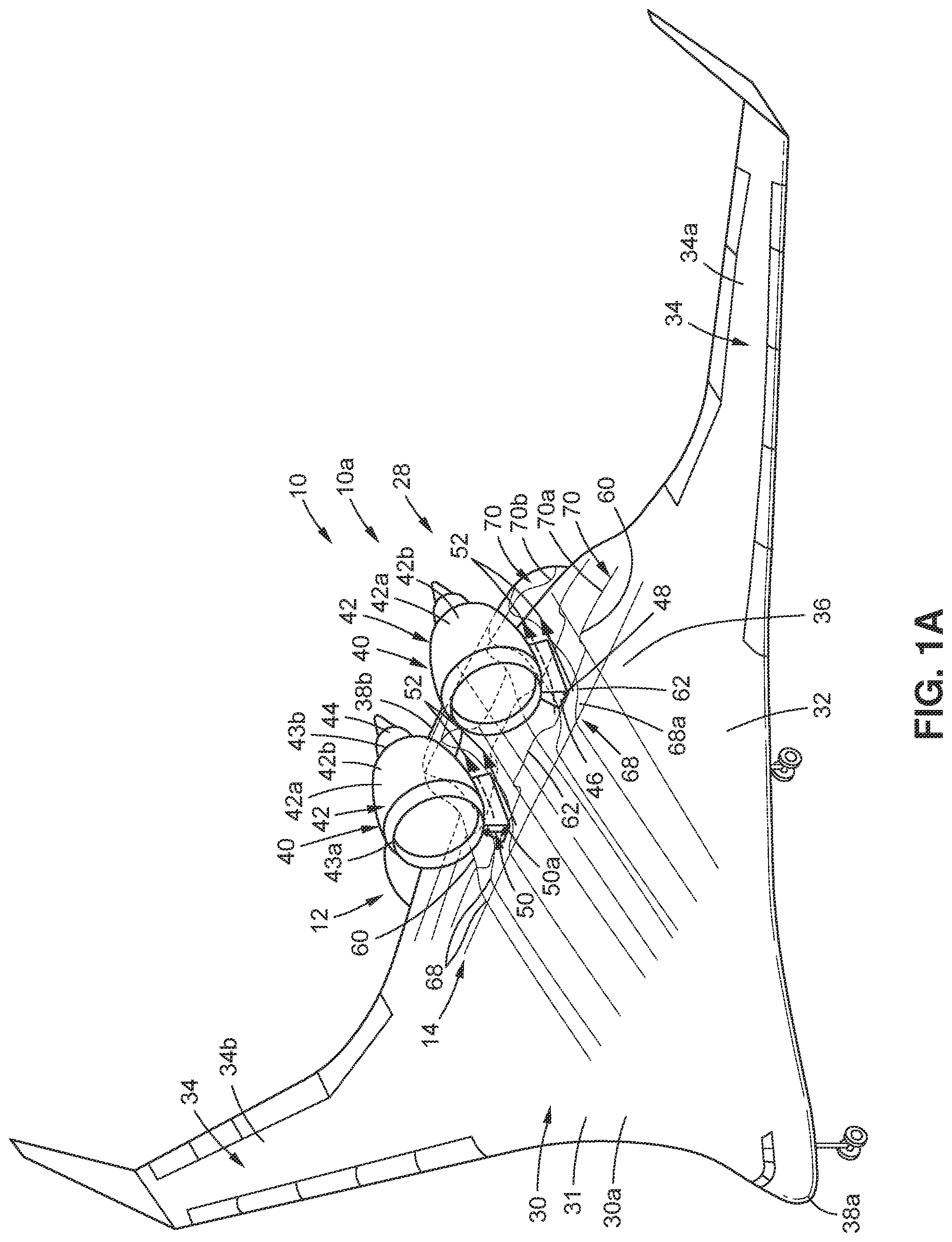
Now referring to A , A is an illustration of a front perspective view of an exemplary version of a vehicle 10 , such as an air vehicle 10 a , in the form of a blended wing body (BWB) aircraft 28 with a version of the vehicle configuration 12 of the disclosure having aerodynamic shaping 14 . As shown in A , the BWB aircraft 28 comprises a vehicle body 30 , or airframe 31 , including a fuselage 32 , and wings 34 smoothly blended with the fuselage 32 . The wings 34 include a first wing 34 a (see A ) and a second wing 34 b (see A ). The vehicle body 30 has an upper surface 36 (see A ). The vehicle 10 , such as the BWB aircraft 28 , has a forward end 38 a (see A ), an aft end 38 b (see A ), and a centerline 39 (see C- 1 D ).
As shown in A , the BWB aircraft 28 further comprises at least one auxiliary body 40 , such as two auxiliary bodies 40 , each attached and suspended above the upper surface 36 of the vehicle body 30 , near the aft end 38 b of the BWB aircraft 28 . As further shown in A , in one version, the auxiliary bodies 40 each comprise a nacelle 42 , such as an engine nacelle 42 a , for example, a top-mounted nacelle 42 b , that houses an engine 44 . As shown in A , the nacelle 42 has a leading edge 43 a and a trailing edge 43 b . Each auxiliary body 40 , such as the nacelle 42 , is in structural communication with the vehicle body 30 , via a structural attachment element 46 (see A ), such as a pylon 48 (see A ). As shown in A , each auxiliary body 40 , such as the nacelle 42 , is positioned a distance 50 , such as an optimal distance 50 a , from the upper surface 36 of the vehicle body 30 , to form a channel 52 , or gap, such as an air gap, between a lower surface 54 of the auxiliary body 40 and the upper surface 36 of the vehicle body 30 , on each side of each auxiliary body 40 , such as the nacelle 42 . As used herein, “optimal distance” means a distance or height between an upper surface or outer surface of a vehicle body and a lower surface of an auxiliary body, where the distance or height is less than a distance or height that creates a large nose-down pitching moment induced by thrust of the auxiliary body, such as a nacelle, and is greater than a distance or height that creates a highly constricted channel flow in a channel between the vehicle body and the auxiliary body, and is preferably a threshold distance, or height below which shocks, such as shock waves, will form in the channel flow and aft recirculation will occur behind the channel flow. The distance or height threshold depends on the vehicle flight speed, Mach number, and Reynolds number, the length of the vehicle ahead of the auxiliary body, the vehicle boundary layer height at the start of the constricted channel, and the vehicle angle of attack. The distance or height threshold is determined with computational fluid dynamics (CFD) modeling or testing and in a non-linear way is relative to the vehicle surface shaping, physical scale, flight speed, flight altitude, the entrance Mach number of the channel flow, and the boundary layer height at the entrance and throughout the channel, and the boundary layer height at the entrance and throughout the channel flow. In short, the optimal distance is a distance with an upper limit constrained by not adversely affecting the vehicle's performance due to large trim drag penalties resulting from excessive pitching moment due to the height of the auxiliary body, and with a lower limit constrained by excessive interference drag coming from the channel flow between the vehicle body and the auxiliary body. A nose-down pitching moment is a torque about a center of gravity that may cause a nose of a vehicle to move downward. The channels 52 , or gaps, are configured to receive fluid flow 56 (see ), such as air flow 58 (see ), through the channel 52 .
As shown in A , in this version, the vehicle body 30 is shaped with the aerodynamic shaping 14 to obtain an aerodynamic shaped vehicle body 30 a , or shape optimized vehicle body. The vehicle configuration 12 comprises the vehicle body 30 , and the auxiliary bodies 40 coupled to, and positioned the distance 50 , such as the optimal distance 50 a , from, the vehicle body 30 , to form the channel 52 , between the auxiliary bodies 40 and the vehicle body 30 . The vehicle configuration 12 further comprises one or more exterior profiles 60 (see A ) of one or more of, the vehicle body 30 and the auxiliary body 40 . As shown in A , the vehicle configuration 12 comprises multiple exterior profiles 60 on the vehicle body 30 . The exterior profiles 60 are positioned in proximity to the channel 52 , where proximity to the channel 52 means, along the length of the channel 52 , parallel to the channel 52 , perpendicular to the length of the channel 52 , lateral to the length of the channel 52 , extending in front of, or forward of, the channel 52 , extending in back of, or aft of, the channel 52 , and/or extending from each side of the channel 52 . Each exterior profile 60 on the vehicle body 30 may extend forward of the leading edge 43 a (see A ) of the auxiliary body 40 , such as the nacelle 42 , or may extend aft of the trailing edge 43 b (see A ) of the auxiliary body 40 , such as the nacelle 42 , or may extend inboard or outboard from the sides of the auxiliary body 40 , such as the nacelle 42 .
The exterior profiles 60 are shaped with the aerodynamic shaping 14 , such as externally shaped, so that each exterior profile 60 comprises one or more concave shape portions 62 and has a concavity 64 (see B- 1 D ). The concave shape portions 62 alternate, in series, in opposite concavities 64 a (see B- 1 D ), or opposite directions. The concave shape portions 62 comprise one or more concave-up portions 66 a (see B- 1 D ) and one or more concave-down portions 66 b (see B- 1 D ). The concave shape portions 62 may be the same size, and have the same height, or the concave shape portions 62 may be of different sizes and different heights.
As shown in A , the exterior profiles 60 shaped with the aerodynamic shaping 14 comprise longitudinal contours 68 formed longitudinally in a longitudinal direction and along the sides of the auxiliary bodies 40 of the vehicle 10 . Each longitudinal contour 68 has one or more concave shape portions 62 , and where the longitudinal contour 68 has two or more concave shape portions 62 , the two or more concave shape portions 62 and the concavity 64 are reversed from the concave-up portion 66 a (see B ) to the concave-down portion 66 b (see B ), longitudinally and in series. The concavity 64 of each longitudinal contour 68 comprises a longitudinal concavity 64 b (see B ) that changes at locations 65 a (see B ). The longitudinal contours 68 blend into the original surface of the vehicle body 30 , as the longitudinal contours 68 get successively farther away from the auxiliary bodies 40 , such as the nacelles 42 .
As shown in A , the exterior profiles 60 shaped with the aerodynamic shaping 14 further comprise lateral contours 70 formed laterally in a lateral direction. Each lateral contour 70 has one or more concave shape portions 62 , and where the lateral contour 70 has two or more concave shape portions 62 , the two or more concave shape portions 62 and the concavity 64 reverse from the concave-up portion 66 a (see C, 1 D ) to the concave-down portion 66 b (see C, 1 D ), laterally and in series. The concavity 64 (see C, 1 D ) of each lateral contour 70 comprises a lateral concavity 64 c (see C, 1 D ) that changes at locations 65 b (see C, 1 D ). As further shown in A , the lateral contours 70 intersect with, or cross, the longitudinal contours 68 on the upper surface 36 of the vehicle body 30 . The lateral contours 70 blend into the original surface of the vehicle body 30 , as the lateral contours 70 get farther away from the auxiliary body 40 , such as the nacelle 42 .
Now referring to B , B is a schematic illustration of a side view of a longitudinal contour 68 , such as a first longitudinal contour 68 a , of A . B shows the auxiliary body 40 , such as the nacelle 42 , positioned above the longitudinal contour 68 , such as the first longitudinal contour 68 a , formed on the upper surface 36 of the vehicle body 30 . As shown in B , the longitudinal contour 68 , such as the first longitudinal contour 68 a , has a first end 69 a facing towards the forward end 38 a (see A ) of the vehicle 10 (see A ), and has a second end 69 b facing towards the aft end 38 b (see A ) of the vehicle 10 . As further shown in B , the longitudinal contour 68 , such as the first longitudinal contour 68 a , has concave shape portions 62 where the concavity 64 , such as the longitudinal concavity 64 b , is reversed from a concave-down portion 66 b , to a concave-up portion 66 a , and to another concave-down portion 66 b , longitudinally and in series. The longitudinal concavity 64 b of the longitudinal contour 68 changes at locations 65 a (see B ). The specific series of concave-down portions 66 b and concave-up portion 66 a shown in B is merely an example of one type of series for the longitudinal contour 68 , and another vehicle body 30 and auxiliary body 40 combination may have a different series of concave-down portions 66 b and/or concave-up portions 66 a.
Now referring to C , C is a schematic illustration of a rear view of a lateral contour 70 , such as a first lateral contour 70 a , of A . C shows the auxiliary bodies 40 , such as the nacelles 42 , on each side of the centerline 39 of the vehicle 10 (see A ), and the nacelles 42 are positioned above the lateral contour 70 , such as the first lateral contour 70 a , formed on the upper surface 36 of the vehicle body 30 . As shown in C , the lateral contour 70 , such as the first lateral contour 70 a , has a first end 71 a facing towards the first wing 34 a (see A ), or left wing, of the vehicle 10 (see A ), from the rear view, and has a second end 71 b facing towards the second wing 34 b (see A ), or right wing, of the vehicle 10 , from the rear view. As further shown in C , the lateral contour 70 , such as the first lateral contour 70 a , has concave shape portions 62 where the concavity 64 , such as the lateral concavity 64 c , is reversed from a concave-down portion 66 b , to a concave-up portion 66 a , to another concave-down portion 66 b , to another concave-up portion 66 a , and to another concave-down portion 66 b , laterally and in series. The lateral concavity 64 c of the first lateral contour 70 a changes at locations 65 b (see C ). The specific series of concave-down portions 66 b and concave-up portions 66 a shown in C is merely an example of one type of series for the lateral contour 70 , and another vehicle body 30 and auxiliary body 40 combination may have a different series of concave-down portions 66 b and/or concave-up portions 66 a.
Now referring to D , D is a schematic illustration of a rear view of a lateral contour 70 , such as a second lateral contour 70 b , of A . D shows the auxiliary bodies 40 , such as the nacelles 42 , on each side of the centerline 39 of the vehicle 10 (see A ), and the nacelles 42 are positioned above the lateral contour 70 , such as the second lateral contour 70 b , formed on the vehicle body 30 . As shown in D , the lateral contour 70 , such as the second lateral contour 70 b , has the first end 71 a facing towards the first wing 34 a (see A ), or left wing, of the vehicle 10 (see A ), from the rear view, and has the second end 71 b facing towards the second wing 34 b (see A ), or right wing, of the vehicle 10 , from the rear view. As further shown in D , the lateral contour 70 , such as the second lateral contour 70 b , has concave shape portions 62 where the concavity 64 , such as the lateral concavity 64 c , is reversed from a concave-up portion 66 a , to a concave-down portion 66 b , to another concave-up portion 66 a , to another concave-down portion 66 b , and to another concave-up portion 66 a , laterally and in series. The lateral concavity 64 c of the second lateral contour 70 b changes at locations 65 b (see D ). The specific series of concave-up portions 66 a and concave-down portions 66 b shown in D is merely an example of one type of series for the lateral contour 70 , and another vehicle body 30 and auxiliary body 40 combination may have a different series of concave-up portions 66 a and/or concave-down portions 66 b.
Now referring to E , E is an illustration of a back perspective partial view of an exemplary vehicle 10 , such as an air vehicle 10 a , for example, in the form of the blended wing body (BWB) aircraft 28 , with a version of the vehicle configuration 12 , such as an aerodynamic shaped vehicle configuration 12 a , having aerodynamic shaping 14 of the disclosure. In this version, the vehicle body 30 is shaped with the aerodynamic shaping 14 , to obtain the aerodynamic shaped vehicle body 30 a (see E ), or shape optimized vehicle body. E shows the aerodynamic shaping 14 on a vehicle body portion 30 b of the vehicle body 30 , such as the fuselage 32 . E further shows the wing 34 , the forward end 38 a , the aft end 38 b , and the auxiliary body 40 of the BWB aircraft 28 .
As shown in E , the auxiliary body 40 is attached to, and suspended above, the upper surface 36 of the vehicle body 30 near the aft end 38 b of the BWB aircraft 28 . As further shown in E , the auxiliary body 40 comprises the nacelle 42 , such as the engine nacelle 42 a , for example, the top-mounted nacelle 42 b , that houses the engine 44 . E further shows the channel 52 formed between the lower surface 54 of the auxiliary body 40 and the upper surface 36 of the vehicle body 30 .
E shows the vehicle configuration 12 with exterior profiles 60 , shaped with the aerodynamic shaping 14 , comprising longitudinal contours 68 with the longitudinal concavity 64 b , and comprising lateral contours 70 with the lateral concavity 64 c , on the vehicle body portion 30 b of the vehicle body 30 . The exterior profiles 60 comprising the longitudinal contours 68 and the lateral contours 70 comprise concave shape portions 62 alternating, in series, in opposite concavities 64 a , or opposite directions. As shown in E , the concave shape portions 62 include the concave-up portions 66 a and the concave-down portions 66 b . With the longitudinal contours 68 , the concave shape portions 62 and the longitudinal concavity 64 b are reversed from the concave-up portion 66 a to the concave-down portion 66 b longitudinally. With the lateral contours 70 , the concave shape portions 62 and the lateral concavity 64 c are reversed from the concave-up portion 66 a to the concave-down portion 66 b laterally.
As shown in E , in this version, the vehicle body 30 is shaped with the aerodynamic shaping 14 on the upper surface 36 of the vehicle body portion 30 b , indicated with a box 78 showing the longitudinal contours 68 and the lateral contours 70 in the area where the aerodynamic shaping 14 occurs. The aerodynamic shaping 14 provides longitudinal contours 68 and lateral contours 70 that are aerodynamic shaped contours 80 (see E ), each having the exterior profile 60 and a three-dimensional (3D) shape 82 (see E ). Successive aerodynamic shaped contours 80 and exterior profiles 60 comprising the longitudinal contours 68 and the lateral contours 70 gradually wash out, or get less pronounced, and blend into the original upper surface 36 of the vehicle body 30 , extending from the channel 52 outward in an outboard direction 84 a and extending from the channel 52 inward in an inboard direction 84 b . The aerodynamic shaping 14 washes out, or gets less pronounced, and blends into the original upper surface 36 of the vehicle body 30 , as the aerodynamic shaping 14 moves in the outboard direction 84 a and the inboard direction 84 b , with the aerodynamic shaping 14 being at a maximum height at the channel 52 and near the centerline of the auxiliary body 40 , such as the nacelle 42 .
Now referring to F , F is an illustration of a front perspective view of an exemplary vehicle 10 , such as an air vehicle 10 a , in the form of an aircraft 72 , such as a commercial aircraft 72 a , with top-mounted nacelles 42 b , and with another version of a vehicle configuration 12 of the disclosure having aerodynamic shaping 14 . As shown in F , the commercial aircraft 72 a comprises a vehicle body 30 , or airframe 31 , including the fuselage 32 , wings 34 attached to the fuselage 32 , and a tail 74 , or empennage. The vehicle 10 , such as the commercial aircraft 72 a , has the forward end 38 a (see F ) and the aft end 38 b (see F ).
As shown in F , the commercial aircraft 72 a further comprises two auxiliary bodies 40 , each attached and suspended above a respective wing 34 of the vehicle body 30 of the commercial aircraft 72 a . As further shown in F , in one version, the auxiliary bodies 40 each comprise the nacelle 42 , such as the engine nacelle 42 a , for example, the top-mounted nacelle 42 b , that houses the engine 44 . Each auxiliary body 40 , such as the nacelle 42 , is in structural communication with the upper surface 36 of the vehicle body 30 , for example, an upper surface 76 a of the wing 34 , via the structural attachment element 46 (see F ), such as the pylon 48 (see F ). Each auxiliary body 40 , such as the nacelle 42 , is positioned a distance 50 (see ), such as an optimal distance 50 a (see ), from the upper surface 36 of the vehicle body 30 , such as the upper surface 76 a of the wing 34 , to form channels 52 , or gaps, between the lower surface 54 of the auxiliary body 40 and the upper surface 36 of the vehicle body 30 , such as the upper surface 76 a of the wing 34 , on each side of the auxiliary body 40 , such as the nacelle 42 .
As shown in F , the vehicle configuration 12 comprises the exterior profiles 60 comprising the longitudinal contours 68 and the lateral contours 70 shaped with the aerodynamic shaping 14 , so that the exterior profiles 60 comprises concave shape portions 62 each having concavity 64 (see ). The concave shape portions 62 alternate, in series, in opposite concavities 64 a (see B ), or opposite directions. The concave shape portions 62 include one or more concave-up portions 66 a (see B ), and one or more concave-down portions 66 b (see B ). As shown in F , the longitudinal contours 68 are formed longitudinally in a longitudinal direction, and each longitudinal contour 68 has concave shape portions 62 , where the longitudinal concavity 64 b (see B ) is reversed from the concave-up portion 66 a to the concave-down portion 66 b , longitudinally and in series. The concavity 64 of each longitudinal contour 68 comprises the longitudinal concavity 64 b that changes in locations 65 a (see B ).
As further shown in F , the exterior profiles 60 shaped with the aerodynamic shaping 14 further comprise lateral contours 70 formed laterally in a lateral direction, and each lateral contour 70 has concave shape portions 62 , where the lateral concavity 64 c (see C ) is reversed from the concave-up portion 66 a (see C ) to the concave-down portion 66 b (see C ), laterally and in series. The concavity 64 of each lateral contour 70 comprises the lateral concavity 64 c that changes in locations 65 b (see C ). As further shown in F , the lateral contours 70 intersect with, or cross, the longitudinal contours 68 .
Now referring to G , G is an illustration of a front perspective view of an exemplary vehicle 10 , such as an air vehicle 10 a , in the form of the aircraft 72 , such as a commercial aircraft 72 b , with bottom-mounted nacelles 42 c , and with yet another version of a vehicle configuration 12 of the disclosure having aerodynamic shaping 14 . As shown in G , the commercial aircraft 72 b comprises the vehicle body 30 , or airframe 31 , including the fuselage 32 , wings 34 attached to the fuselage 32 , and the tail 74 , or empennage. The vehicle 10 , such as the commercial aircraft 72 b , has the forward end 38 a (see G ) and the aft end 38 b (see G ).
As shown in G , the commercial aircraft 72 b further comprises two auxiliary bodies 40 , each attached and suspended partially below the respective wing 34 of the vehicle body 30 of the commercial aircraft 72 b . As further shown in G , in one version, each auxiliary body 40 comprises the nacelle 42 , such as the engine nacelle 42 a , for example, the bottom-mounted nacelle 42 c , that houses the engine 44 . Each auxiliary body 40 , such as the nacelle 42 , is attached to a lower surface 76 b (see G ) of the wing 34 of the vehicle body 30 . Each auxiliary body 40 , such as the nacelle 42 , is positioned a distance 50 (see ) from the wing 34 of the vehicle body 30 , to form the channels 52 , between an upper surface 55 of the auxiliary body 40 and the lower surface 76 b of the wing 34 of the vehicle body 30 . As shown in G , the vehicle configuration 12 comprises the exterior profiles 60 comprising the longitudinal contours 68 and the lateral contours 70 shaped with the aerodynamic shaping 14 , so that the exterior profiles 60 comprise concave shape portions 62 alternating, in series, in opposite concavities 64 a (see ), or opposite directions. In this version, the wings 34 of the vehicle body 30 are shaped with the aerodynamic shaping 14 to obtain the aerodynamic shaped vehicle body 30 a (see G ), or shape optimized vehicle body.
Now referring to , is an illustration of a functional block diagram showing exemplary versions of a vehicle 10 having exemplary versions of a vehicle configuration 12 of the disclosure. The blocks in represent elements, and lines connecting the various blocks do not imply any particular dependency of the elements. Furthermore, the connecting lines shown in the various Figures contained herein are intended to represent example functional relationships and/or physical couplings between the various elements, but it is noted that other alternative or additional functional relationships or physical connections may be present in versions disclosed herein. One or more of these blocks may be combined, divided, or combined and divided into different blocks when implemented in an illustrative example. Further, the illustrations of the vehicle 10 and the vehicle configuration 12 in are not meant to imply physical or architectural limitations to the manner in which illustrative examples may be implemented. Other components in addition to, or in place of, the ones illustrated may be used. Some components may be unnecessary.
In one version of the disclosure, there is provided a vehicle configuration 12 (see ), with aerodynamic shaping 14 , to reduce drag 16 (see ), such as interference drag 18 (see ), in a fluid stream 20 (see ), such as an air stream 22 (see ). In another version of the disclosure, there is provided a vehicle 10 (see ) having the vehicle configuration 12 .
As shown in , the vehicle 10 preferably comprises an air vehicle 10 a . As further shown in , the vehicle 10 may comprise a blended wing body (BWB) aircraft 28 , an aircraft 72 , such as a commercial aircraft 72 a , 72 b (see also F, 1 G ), or a military aircraft 72 c , a launch vehicle 86 , such as a rocket-propelled vehicle 88 , a spacecraft 90 , or another suitable vehicle. The aerodynamic shaping 14 is particularly suitable for a propulsion airframe integration (PAI) 91 (see ) of a top-mounted nacelle 42 b (see ) with a pylon 48 (see ) on a BWB aircraft 28 .
As further shown in , the vehicle configuration 12 , such as an aerodynamic shaped vehicle configuration (CONFIG.) 12 a , or shape optimized vehicle configuration, comprises the vehicle body 30 , such as an aerodynamic (AERO) shaped vehicle body 30 a . As further shown in , the vehicle body 30 , in one version, such as for the BWB aircraft 28 and aircraft 72 , comprises an airframe 31 , including a fuselage 32 , one or more wings 34 , a tail 74 (see F ), or other suitable structures. The vehicle body 30 , in another version, such as for the launch vehicle 86 comprises a main body 92 (see , 6 A ), or another suitable body structure.
As further shown in , the vehicle configuration 12 , such as the aerodynamic shaped vehicle configuration 12 a , comprises at least one auxiliary body 40 , or one or more auxiliary bodies 40 , each positioned, or offset, a distance 50 , such as an optimal distance 50 a , from the vehicle body 30 , to form a channel 52 , or gap, between the auxiliary body 40 and the vehicle body 30 . In one version, such as for the BWB aircraft 28 (see A ) and aircraft 72 , the lower surface 54 of the auxiliary body 40 is positioned opposite to, and faces, the upper surface 36 of the vehicle body 30 . In another version, such as for the launch vehicle 86 (see A ), the rocket-propelled vehicle 88 (see A ), or the spacecraft 90 , the lower surface 54 (see ), such as a side surface 94 (see , 6 A ) of the auxiliary body 40 is positioned opposite to, and faces, an outer surface 37 (see , 6 A ), or exterior surface, of the vehicle body 30 . When the at least one auxiliary body 40 is shaped with the aerodynamic shaping 14 and shape optimization 109 (see ), at least one aerodynamic (AERO) shaped auxiliary body 40 a (see ), or shape optimized auxiliary body, is obtained.
As further shown in , the auxiliary body 40 may comprise a nacelle 42 , an engine nacelle 42 a , a top-mounted nacelle 42 b , a fuel tank 96 , a pod 98 , such as a sensor pod 98 a , a booster 100 , a missile 102 , or another suitable body coupled to, and in proximity to, the vehicle body 30 . As shown in C , the auxiliary body 40 may also comprise a bottom-mounted nacelle 42 c . The auxiliary body 40 is in structural communication, for example, via a structural (STRUCT.) attachment element 46 (see ), such as a pylon 48 (see ), with the vehicle body 30 . The pylon 48 may also be shaped with the aerodynamic shaping 14 (see ), as discussed in further detail below with respect to C- 5 D . As shown in C , the pylon 48 has an outboard exterior profile 146 and an inboard exterior profile 148 , where one or more of, the outboard exterior profile 146 and the inboard exterior profile 148 , may be shaped with the aerodynamic shaping 14 .
Where the auxiliary body 40 comprises the nacelle 42 , the nacelle 42 , in one version, as shown in A, 1 F , is suspended above the vehicle body 30 . In another version, as shown in G , the nacelle 42 is suspended below the vehicle body 30 , such as below the wing 34 .
As further shown in , the vehicle configuration 12 , such as the aerodynamic shaped vehicle configuration 12 a , comprises the exterior profile 60 of one or more of, the vehicle body 30 and the auxiliary body 40 , shaped, such as externally shaped, with the aerodynamic shaping 14 , so that the exterior profile 60 comprises one or more concave shape portions 62 (see ). As discussed above, the aerodynamic shaping 14 provides aerodynamic shaped contours 80 (see ), each having the exterior profile 60 and the three-dimensional (3D) shape 82 (see ). As shown in , the aerodynamic shaping 14 includes longitudinal (LONG.) contours 68 and lateral (LAT.) contours 70 .
As discussed above, where the exterior profile 60 comprises two or more concave shape portions 62 , the two or more concave shape portions 62 alternate, in series, in opposite concavities 64 a (see ), or directions. As shown in , the concave shape portions 62 include one or more concave-up portions 66 a , and/or one or more concave-down portions 66 b . The concave shape portions 62 and the concavity 64 are reversed from the concave-up portion 66 a to the concave-down portion 66 b longitudinally, and reversal of the concavity 64 also occurs laterally between the exterior profiles 60 . Each exterior profile 60 also has one or more curvature inflection points 104 (see , 4 A ).
As further shown in , the vehicle configuration 12 and the aerodynamic shaping 14 may be modeled with a computer modeling software, program, or system, such as a CAD (computer-aided design) software program, for example, a parametric CAD software program, or computational fluid dynamics (CFD) mesh morphing using parametric or non-parametric mesh morphing tools, to obtain a three-dimensional (3D) model 106 (see ). Other suitable modeling software programs or systems may also be used. Further, the 3D model 106 and the aerodynamic shaping 14 may be optimized with an optimization approach 108 (see ) or process, or method, to perform shape optimization 109 (see ), including, for example, an initial shape optimization 109 a (see ). The 3D model 106 with the aerodynamic shaping 14 may then be optimized and analyzed and tested through flow simulations using a computational fluid dynamics (CFD) design optimization software program, or another suitable flow simulation software or program, to optimize the aerodynamic shaping 14 of the vehicle body 30 and the auxiliary body 40 forming the channel 52 , leading to optimal fluid flow 56 , such as air flow 58 , in the channel 52 , that results in the reduction of drag 16 , such as interference drag 18 , and/or reduced likelihood of structural fatigue, and/or to optimize the aerodynamic shaping 14 of the structural attachment element 46 , such as the pylon 48 , discussed below with respect to C- 5 D . The amount of aerodynamic shaping 14 made to one or more exterior profiles 60 of a vehicle 10 may be particular to the auxiliary body 40 , such as the nacelle 42 , used with the vehicle 10 , and the amount of the aerodynamic shaping 14 may be different for different vehicles.
In one version, only the exterior profile 60 of the upper surface 36 , or the outer surface 37 , of the vehicle body 30 is shaped, such as externally shaped, with the aerodynamic shaping 14 , to obtain the aerodynamic shaped vehicle body 30 a (see ), or shape optimized vehicle body. In another version, only the exterior profile 60 of the lower surface 54 of the auxiliary body 40 is shaped with the aerodynamic shaping 14 , to obtain the aerodynamic shaped auxiliary body 40 a (see ), or shape optimized auxiliary body. In another version, both the exterior profile 60 of the upper surface 36 , or the outer surface 37 , of the vehicle body 30 , and the exterior profile 60 of the lower surface 54 of the auxiliary body 40 are shaped, such as externally shaped, with the aerodynamic shaping 14 . Further, if the structural attachment element 46 , such as the pylon 48 , is present, the structural attachment element 46 , such as the pylon 48 , may be shaped, such as externally shaped, with the aerodynamic shaping 14 , alone, or in combination with one of, the aerodynamic shaped vehicle body 30 a , the aerodynamic shaped auxiliary body 40 a , or both the aerodynamic shaped vehicle body 30 a and the aerodynamic shaped auxiliary body 40 a . The aerodynamic shaping 14 of the pylon 48 is discussed in further detail below with respect to C- 5 D . Further, the exterior profile 60 of the vehicle body 30 may be shaped at a location aft of the auxiliary body 40 with the aerodynamic shaping 14 , such as in the form of aft aerodynamic shaping 14 a (see ).
The vehicle configuration 12 with the aerodynamic shaping 14 is designed to reduce drag 16 (see ), such as interference drag 18 (see ), in a fluid stream 20 (see ), such as an air stream 22 (see ), to obtain a reduced drag 16 a (see ), such as a reduced interference drag 18 a (see ). The interference drag 18 may include compressibility drag 112 (see ). Further, the vehicle configuration 12 with the aerodynamic shaping 14 is designed to reduce compressibility drag 112 , to obtain a reduced compressibility drag 112 a (see ).
As used herein, “interference drag” means drag that is generated when a fluid flow or air flow across a component of a vehicle, for example, an aircraft, is forced to mix with the fluid flow or air flow across an adjacent or proximal component, for example, a nacelle and a fuselage, or a nacelle and a wing. As fluid flow, or air flow, flows around the different vehicle or aircraft components, and mixes, localized shock waves, or shocks, and regions of recirculating air flow are formed, creating a drag sum greater than a drag that the vehicle or aircraft components would have by themselves. Interference drag may include compressibility drag, skin-friction drag, pressure drag, and drag from air recirculation.
With the aerodynamic shaping 14 of the vehicle 10 , when the fluid flow (FF) 56 (see ) of fluid 114 (see ), such as the air flow (AF) 58 (see ) of air 116 (see ), from the fluid stream 20 , such as the air stream 22 , flows through the channel 52 , the drag 16 , such as the interference drag 18 , resulting from fluid flow interactions 118 (see ), or mixing, such as air flow interactions 120 (see ), or mixing, between the vehicle body 30 and the auxiliary body 40 is reduced.
The fluid flow 56 , such as an air flow 58 , from the fluid stream 20 , such as the air stream 22 , comprises a compressible fluid flow 56 a (see ), such as a compressible air flow 58 a (see ), moving at one of, transonic speed 24 (see ), subsonic speed 26 (see ), or supersonic speed 27 (see ), through the channel 52 . As shown in , the channel 52 provides a flow channel 52 a , for example, a fluid flow channel 52 b , or an air flow channel 52 c , between the auxiliary body 40 and the vehicle body 30 , configured to allow channel flow 53 , such as fluid flow 56 , for example, air flow 58 , to flow through the channel 52 . As further shown in , the channel flow 53 may be optimized with the optimization approach 108 to obtain an optimized channel flow 53 a . The optimization approach 108 , or process, provides for shape optimization 109 (see ) along the channel 52 , of the exterior profile 60 of one or more of, the vehicle body 30 , the auxiliary body 40 , and the pylon 48 , if present. As further shown in , prior to the air flow 58 flowing into the channel 52 , the air flow 58 is in the form of upstream air flow (AF) 58 b , and after the air flow 58 flows through the channel 52 and exits the channel 52 , the air flow 58 is in the form of exhaust air flow (AF) 58 c . The vehicle body 30 has an air flow (AF) path 58 d (see ) in the channel 52 , and the auxiliary body 40 has an air flow path 58 d in the channel 52 , when air flow 58 flows through the channel 52 .
To avoid a shock wave 122 (see ) or to reduce a strength 124 (see ) of the shock wave 122 that may be created within the channel 52 between the vehicle body 30 and the auxiliary body 40 , during flight of the vehicle 10 at transonic speed 24 , or velocity, or subsonic speed 26 , or velocity, or supersonic speed 27 , or velocity, the exterior profile 60 of one or more of, the vehicle body 30 and the auxiliary body 40 , and optionally, the pylon 48 , if present, are shaped with the aerodynamic shaping 14 . Thus, the aerodynamic shaping 14 of the exterior profile 60 of one or more of, the vehicle body 30 and the auxiliary body 40 , and optionally, the pylon 48 , if present, results in a reduced shock wave strength 124 a (see ).
Further, the exterior profile 60 of the vehicle body 30 , such as a vehicle body aft surface 30 e (see B ), of the exterior profile 60 of the upper surface 36 of the vehicle body 30 , may be shaped aft of the auxiliary body 40 with the aerodynamic shaping 14 , such as the aft aerodynamic shaping 14 a , to reduce aft recirculation 126 (see ) and aft recirculation zones 126 a (see ) of recirculation fluid flow (FF) 56 b (see ), or separated fluid flow (FF) 56 c (see ), for example, recirculation air flow (AF) 58 e (see ), or separated air flow (AF) 58 f (see ), formed aft of the auxiliary body 40 . The aerodynamic shaping 14 , such as the aft aerodynamic shaping 14 a , of the exterior profile 60 of the vehicle body 30 aft of the auxiliary body 40 results in reduced aft recirculation (RECIRC.) 126 b (see ). As used herein, “recirculation” means fluid flow or air flow that moves and curls back on itself, relative to the direction of the fluid flow or air flow far upstream, because it is moving through the channel between the auxiliary body and the vehicle body at transonic speeds, or subsonic speeds, or supersonic speeds.
Now referring to A- 3 C , A- 3 C show various unshaped vehicle configurations 128 , or non-optimized vehicle configurations, of an unshaped vehicle 10 b , or a non-optimized vehicle, with no aerodynamic shaping 14 (see ). Associated issues may result from such unshaped vehicle configurations 128 . A- 3 C show the auxiliary body 40 , such as an unshaped auxiliary body 40 b , or non-optimized auxiliary body, in the form of a top-mounted nacelle 42 b , with no aerodynamic shaping 14 (see C ), mounted, via a pylon 48 , above an upper surface 36 , of the vehicle body 30 , such as an unshaped vehicle body 30 c , or non-optimized vehicle body, with no aerodynamic shaping 14 (see A ). A- 3 C further show upstream air flow 58 b flowing in a forward-to-aft direction 130 toward the top-mounted nacelle 42 b , and further show a center of gravity 132 .
A shows a schematic illustration of a side view of the unshaped vehicle configuration 128 , such as a first unshaped vehicle configuration 128 a , of the unshaped vehicle 10 b , with no aerodynamic shaping 14 (see ), and having the auxiliary body 40 , such as the unshaped auxiliary body 40 b , or non-optimized auxiliary body, in the form of the top-mounted nacelle 42 b , mounted a distance 50 , such as a high distance 50 b , above the upper surface 36 , of the vehicle body 30 , such as the unshaped vehicle body 30 c , or non-optimized vehicle body. A shows a center of gravity 132 , a thrust moment arm 134 , the upstream air flow 58 b , and a thrust line 135 extending longitudinally through the top-mounted nacelle 42 b . To decouple an added drag effect of the top-mounted nacelle 42 b on the vehicle body 30 , the top-mounted nacelle 42 b is displaced, or positioned, a high distance 50 b above the vehicle body 30 . However, higher displacement may create a large nose-down pitching moment induced by thrust of the top-mounted nacelle 42 b , which may make it difficult to trim the unshaped vehicle 10 b across a flight envelope (i.e., operational limits that a vehicle, such as an aircraft, is safe to fly in), and more particularly, during takeoff of the unshaped vehicle 10 b.
B shows a schematic illustration of a side view of another unshaped vehicle configuration 128 , such as a second unshaped vehicle configuration 128 b , of the unshaped vehicle 10 b , having no aerodynamic shaping 14 (see A ), and having the auxiliary body 40 , such as the unshaped auxiliary body 40 b , or non-optimized auxiliary body, in the form of the top-mounted nacelle 42 b , mounted a distance 50 , such as an intermediate distance 50 c , above the upper surface 36 , of the vehicle body 30 , such as the unshaped vehicle body 30 c , or non-optimized vehicle body. The second unshaped vehicle configuration 128 b introduces a channel flow 53 and drag (D) 16 , such as interference drag 18 (see ). B shows introduction of the channel flow 53 in the channel 52 formed between the auxiliary body 40 and vehicle body 30 . As shown in B , to avoid a nose-down pitching moment, the auxiliary body 40 , such as the unshaped auxiliary body 40 b , or non-optimized auxiliary body, in the form of the top-mounted nacelle 42 b , is lowered closer to the vehicle body 30 , such as the unshaped vehicle body 30 c , or non-optimized vehicle body. As the top-mounted nacelle 42 b approaches the vehicle body 30 , the respective air flow paths 58 d (see ) for both the top-mounted nacelle 42 b and the vehicle body 30 begin to couple and channel flow 53 occurs, along with the introduction of drag (D) 16 , such as interference drag 18 . B further shows the upstream air flow 58 b and the center of gravity 132 .
C shows a schematic illustration of a side view of yet another unshaped vehicle configuration 128 , such as a third unshaped vehicle configuration 128 c , of the unshaped vehicle 10 b , having no aerodynamic shaping 14 (see ), and having the auxiliary body 40 , such as the unshaped auxiliary body 40 b , or non-optimized auxiliary body, in the form of the top-mounted nacelle 42 b , mounted a distance 50 , such as a short distance 50 d , above the upper surface 36 , of the vehicle body 30 , such as the unshaped vehicle body 30 c , or non-optimized vehicle body. The third unshaped vehicle configuration 128 c introduces a constricted channel flow 53 b in the channel 52 and drag (D) 16 , such as interference drag 18 (see ). When the unshaped auxiliary body 40 b , or non-optimized auxiliary body, in the form of the top-mounted nacelle 42 b , is positioned too close to the vehicle body 30 , such as the unshaped vehicle body 30 c , or non-optimized vehicle body, although the nose-down pitching moment is reduced, drag 16 , such as interference drag 18 , may grow very quickly due to the constricted channel flow 53 b , and a resulting performance degradation may lead to unfulfilled mission requirements, such as range. C further shows the upstream air flow 58 b and the center of gravity 132 .
Now referring to A- 4 D , A- 4 D show a vehicle 10 having various vehicle configurations 12 of the disclosure with aerodynamic shaping 14 . A- 4 D show the auxiliary body 40 , such as the nacelle 42 , in the form of the top-mounted nacelle 42 b , mounted, via the pylon 48 , at a distance 50 , such as an optimal distance 50 a , above the upper surface 36 of the vehicle body 30 , for example, the fuselage 32 . A- 4 D further show upstream air flow 58 b flowing in a forward-to-aft direction 130 toward the top-mounted nacelle 42 b , and show a center of gravity 132 of the vehicle 10 . A- 4 D further show the channel flow 53 through the channel 52 between the lower surface 54 of the auxiliary body 40 and the upper surface 36 of the vehicle body 30 .
A- 4 D further show three locations 136 having a channel height 138 that is sufficient or effective to obtain a reduced shock wave strength 124 a (see ) and a reduced aft recirculation 126 b (see ). A- 4 D show a location 136 , such as a first location 136 a , with a channel height 138 , such as a first channel height 138 a , between a leading edge lower surface portion 54 a , or highlight, of the auxiliary body 40 , such as the top-mounted nacelle 42 b , and an upper surface first portion 36 a of the vehicle body 30 . A- 4 D show a location 136 , such as a second location 136 b , with a channel height 138 , such as a second channel height 138 b , between a maximum diameter point lower surface 54 b of the auxiliary body 40 , such as the top-mounted nacelle 42 b , and an upper surface second portion 36 b of the vehicle body 30 . A- 4 D show a location 136 , such as a third location 136 c , with a channel height 138 , such as a third channel height 138 c , between a trailing edge lower surface 54 c of the auxiliary body 40 , such as the top-mounted nacelle 42 b , and an upper surface third portion 36 c of the vehicle body 30 .
Now referring to A , A is a schematic illustration of a side view of a version of a vehicle configuration 12 , such as an aerodynamic shaped vehicle configuration 12 a , of the disclosure, having the auxiliary body 40 , such as the nacelle 42 , for example, the top-mounted nacelle 42 b , mounted, via the pylon 48 , a distance 50 , such as an optimal distance 50 a , above the vehicle body 30 , for example, the fuselage 32 , and having aerodynamic shaping 14 of the upper surface 36 of the vehicle body 30 , to obtain an aerodynamic shaped vehicle body 30 a , or shape optimized vehicle body.
A shows the exterior profile 60 of the upper surface 36 of the vehicle body 30 shaped, such as externally shaped, with the aerodynamic shaping 14 to have concave shape portions 62 alternating, in series, in opposite concavities 64 a (see B ), or opposite directions, and an aerodynamic shaped contour 80 . The concave shape portions 62 include one or more concave-up portions 66 a and one or more concave-down portions 66 b . A further shows curvature inflection points 104 , denoted by arrows, along the exterior profile 60 . The curvature inflection points 104 indicate where the concavity 64 is reversed from the concave-up portion 66 a to the concave-down portion 66 b , longitudinally along the exterior profile 60 . Longitudinal spacing of the curvature inflection points 104 depends on contours 137 (see A ) of the lower surface 54 of the auxiliary body 40 , such as the top-mounted nacelle 42 b , and Mach number of the upstream air flow 58 b . Further, z displacement 220 (see D ) between the lower surface 54 of the auxiliary body 40 , such as the top-mounted nacelle 42 b , and the upper surface 36 of the vehicle body 30 varies longitudinally and with Mach number of the upstream air flow 58 b , with at least the three locations 136 having the channel heights 138 that provide a height distribution through the channel 52 that is sufficient, or effective, to obtain reduced shock wave strength 124 a (see ) and reduced aft recirculation 126 b (see ).
A further shows the three locations 136 having the channel height 138 that is sufficient, or effective, to obtain reduced shock wave strength 124 a (see ) and reduced aft recirculation 126 b (see ) with the aerodynamic shaping 14 . In one version, a maximum aerodynamic shaping height to be carved out, or removed, from the upper surface 36 of the vehicle body 30 may be determined by calculating and using the greater of, either a difference between the first channel height 138 a and the second channel height 138 b , and maintaining the difference between the second channel height 138 b and the third channel height 138 c to be similar. This is applicable to the versions of the aerodynamic shaped vehicle body 30 a , in A and 4 B , as well as an initial shape optimized vehicle body 30 d of D .
A further shows the upstream air flow 58 b , the center of gravity 132 of the vehicle 10 , and the channel flow 53 through the channel 52 . The aerodynamic shaping 14 and shape optimization 109 (see ) of the upper surface 36 of the vehicle body 30 optimize the channel flow 53 and result in reduced drag 16 a (see ), such as reduced interference drag 18 a (see ), and reduced aft recirculation 126 b (see ), and reduced likelihood of structural fatigue.
Now referring to B , B is a schematic illustration of a side view of another version of a vehicle configuration 12 , such as an aerodynamic shaped vehicle configuration 12 b , for the vehicle 10 , where the vehicle configuration 12 has the auxiliary body 40 , such as the nacelle 42 , for example, the top-mounted nacelle 42 b , mounted, via the pylon 48 , the distance 50 , such as the optimal distance 50 a , above the vehicle body 30 , for example, the fuselage 32 , and having aerodynamic shaping 14 of both the upper surface 36 of the vehicle body 30 and the lower surface 54 of the auxiliary body 40 , such as the nacelle 42 , for example, the top-mounted nacelle 42 b , to obtain both an aerodynamic shaped vehicle body 30 a , or shape optimized vehicle body, and an aerodynamic shaped auxiliary body 40 a , or shape optimized auxiliary body.
B shows the exterior profile 60 of the upper surface 36 of the vehicle body 30 shaped with the aerodynamic shaping 14 to have concave shape portions 62 alternating, in series, in opposite concavities 64 a (see B ), or opposite directions, and the aerodynamic shaped contour 80 . B further shows the exterior profile 60 of the lower surface 54 of the auxiliary body 40 shaped with the aerodynamic shaping 14 to have concave shape portions 62 alternating, in series, in opposite concavities 64 a , or opposite directions, and the aerodynamic shaped contour 80 . The concave shape portions 62 of the exterior profiles 60 include concave-up portions 66 a and concave-down portions 66 b . B further shows curvature inflection points 104 , denoted by arrows, along the exterior profile 60 of the upper surface 36 of the vehicle body 30 . The curvature inflection points 104 indicate where the concavity 64 is reversed from the concave-up portion 66 a to the concave-down portion 66 b , longitudinally along the exterior profile 60 of the upper surface 36 of the vehicle body 30 .
With the aerodynamic shaped vehicle configuration 12 b of B , a compromise in the amount of aerodynamic shaping 14 may be made between the lower surface 54 of the auxiliary body 40 and the upper surface 36 of the vehicle body 30 , to avoid constriction of the channel 52 . The aerodynamic shaping 14 of the lower surface 54 of the auxiliary body 40 , such as the nacelle 42 , may be similar to the aerodynamic shaping 14 of the upper surface 36 of the vehicle body 30 . However, less aerodynamic shaping 14 of the auxiliary body 40 , such as the nacelle 42 , may be made due to compact packing of internal sub-systems near the lower surface 54 .
B further shows the first location 136 a , the second location 136 b , and the third location 136 c , having the first channel height 138 a , the second channel height 138 b , and the third channel height 138 c , respectively, that provide a height distribution through the channel 52 that is sufficient or effective to obtain reduced shock wave strength 124 a (see ) and reduced aft recirculation 126 b (see ) with the aerodynamic shaping 14 . B further shows the upstream air flow 58 b , the center of gravity 132 of the vehicle 10 , and the channel flow 53 through the channel 52 . The aerodynamic shaping 14 and shape optimization 109 (see ) of both the upper surface 36 of the vehicle body 30 and the lower surface 54 of the auxiliary body 40 optimize the channel flow 53 and result in reduced drag 16 a (see ), such as reduced interference drag 18 a (see ), and reduced aft recirculation 126 b (see ), and reduced likelihood of structural fatigue.
Now referring to C , C is a schematic illustration of a side view of yet another version of a vehicle configuration 12 , such as an aerodynamic shaped vehicle configuration 12 c , for the vehicle 10 , having the auxiliary body 40 , such as the nacelle 42 , for example, the top-mounted nacelle 42 b , mounted, via the pylon 48 , the distance 50 , such as the optimal distance 50 a , above the vehicle body 30 , for example, the fuselage 32 , and having aerodynamic shaping 14 of only the lower surface 54 of the auxiliary body 40 , such as the nacelle 42 , for example, the top-mounted nacelle 42 b , to obtain the aerodynamic shaped auxiliary body 40 a , or shape optimized auxiliary body. C shows the exterior profile 60 of the lower surface 54 of the auxiliary body 40 shaped with the aerodynamic shaping 14 to have concave shape portions 62 alternating, in series, in opposite concavities 64 a (see B ), or opposite directions, and the aerodynamic shaped contour 80 . The concave shape portions 62 of the exterior profiles 60 include one or more concave-up portions 66 a and one or more concave-down portions 66 b . The aerodynamic shaping 14 of the lower surface 54 of the auxiliary body 40 , such as the nacelle 42 , may be minimized, or not as great as, the aerodynamic shaping 14 of the upper surface 36 of the vehicle body 30 , due to compact packing of internal sub-systems near the lower surface 54 .
C further shows the first location 136 a , the second location 136 b , and the third location 136 c , having the first channel height 138 a , the second channel height 138 b , and the third channel height 138 c , respectively, that provide a height distribution through the channel 52 that is sufficient, or effective, to obtain reduced shock wave strength 124 a (see ) and reduced aft recirculation 126 b (see ) with the aerodynamic shaping 14 . B further shows the upstream air flow 58 b , the center of gravity 132 of the vehicle 10 , and the channel flow 53 through the channel 52 . The aerodynamic shaping 14 and shape optimization 109 (see ) of the lower surface 54 of the auxiliary body 40 optimize the channel flow 53 and result in reduced drag 16 a (see ), such as reduced interference drag 18 a (see ), and reduced likelihood of structural fatigue.
Now referring to D , D is a schematic illustration of a side view of yet another version of a vehicle configuration 12 , such as an aerodynamic shaped vehicle configuration 12 d , of the disclosure, having the auxiliary body 40 , such as the nacelle 42 , for example, the top-mounted nacelle 42 b , mounted, via the pylon 48 , a distance 50 , such as an optimal distance 50 a , above the vehicle body 30 , for example, the fuselage 32 . In this version, the upper surface 36 of the vehicle body 30 undergoes an initial shape optimization 109 a (see ), to obtain the initial shape optimized vehicle body 30 d.
In this version of initializing the vehicle configuration 12 , such as the aerodynamic shaped vehicle configuration 12 d , a contoured profile 140 (see D ) of the lower surface 54 of the auxiliary body 40 , such as the nacelle 42 , for example, the top-mounted nacelle 42 b , is carved out, or cut out, or removed, from the upper surface 36 of the vehicle body 30 , such as the fuselage 32 , so that the exterior profile 60 of the upper surface 36 of the vehicle body 30 with the aerodynamic shaping 14 is the same, or similar, to the contoured profile 140 of the lower surface 54 of the auxiliary body 40 that does not have aerodynamic shaping 14 . In other words, the contoured profile 140 of the lower surface 54 of the nacelle 42 is carved or cut into the upper surface 36 of the vehicle body 30 , so that the exterior profile 60 of the upper surface 36 of the vehicle body 30 matches the contoured profile 140 of the original auxiliary body 40 , or nacelle 42 .
D shows the exterior profile 60 of the upper surface 36 of the vehicle body 30 , such as the initial shape optimized vehicle body 30 d , shaped with the aerodynamic shaping 14 to have concave shape portions 62 alternating, in series, in opposite concavities 64 a (see B ), or opposite directions, and the aerodynamic shaped contour 80 . The concave shape portions 62 include one or more concave-up portions 66 a and one or more concave-down portions 66 b.
D further shows the first location 136 a , the second location 136 b , and the third location 136 c , having the first channel height 138 a , the second channel height 138 b , and the third channel height 138 c , respectively, that provide a height distribution through the channel 52 that is sufficient, or effective, to obtain reduced shock wave strength 124 a (see ) and reduced aft recirculation 126 b (see ) with the aerodynamic shaping 14 . D further shows the upstream air flow 58 b , the center of gravity 132 of the vehicle 10 , and the channel flow 53 through the channel 52 . The aerodynamic shaping 14 and the initial shape optimization 109 a (see ), of the upper surface 36 of the vehicle body 30 optimize the channel flow 53 and result in reduced drag 16 a (see ), such as reduced interference drag 18 a (see ), and reduced aft recirculation 126 b (see ), and reduced likelihood of structural fatigue.
Now referring to A , A is a schematic illustration of a front perspective partial view of a vehicle 10 , such as an air vehicle 10 a , showing a structural attachment element 46 , such as in the form of a pylon 48 , suspending an auxiliary body 40 , such as a nacelle 42 , for example, a top-mounted nacelle 42 b , above a vehicle body 30 , such as a fuselage 32 , and attaching the auxiliary body 40 , such as the nacelle 42 , for example, the top-mounted nacelle 42 b , to an upper surface section 36 d of the upper surface 36 of the vehicle body 30 . The pylon 48 contains internal structures (not shown) connecting and attaching the auxiliary body 40 , such as the nacelle 42 , and/or attaching the engine 44 , or other structure, housed within the nacelle 42 , to the upper surface section 36 d of the upper surface 36 of the vehicle body 30 , and/or to structures within the vehicle body 30 , or fuselage 32 . The internal structures in the pylon 48 may include beams, ribs, frames, or other suitable internal structures.
A further shows the channels 52 on each side of the auxiliary body 40 . The channels 52 are formed between the lower surface 54 of the auxiliary body 40 , such as the nacelle 42 , for example, the top-mounted nacelle 42 b , and the upper surface 36 of the vehicle body 30 , such as the fuselage 32 . The pylon may also be referred to as an aero fairing. Since the pylon 48 is like a stubby wing, it has a similar aerodynamic effect on the channel flow 53 (see ) through the channels 52 , as the auxiliary body 40 , such as the nacelle 42 , has, and as the vehicle body 30 , such as the fuselage 32 , has as well.
Now referring to B , B is a schematic illustration of a front perspective view of the structural attachment element 46 , such as in the form of the pylon 48 , of A , where the pylon 48 has no aerodynamic shaping 14 (see ), and is in the form of an unshaped pylon 48 b , or non-optimized pylon. B shows the structural attachment element 46 , such as the pylon 48 , attached to the upper surface section 36 d of the upper surface 36 (see A ) of the vehicle body 30 (see A ). As shown in B , the structural attachment element 46 , such as the pylon 48 , comprises a top end 142 a , a bottom end 142 b , an outboard side 144 a (see also A ), an inboard side 144 b , a leading edge 145 a , and a trailing edge 145 b . The leading edge 145 a and the trailing edge 145 b are airfoil shaped. As further shown in B , the outboard side 144 a has an outboard exterior profile 146 , including an outboard exterior profile top end 146 a and an outboard exterior profile bottom end 146 b . As further shown in B , the inboard side 144 b has an inboard exterior profile 148 , including an inboard exterior profile top end 148 a and an inboard exterior profile bottom end 148 b.
Now referring to C , C is a schematic illustration of a front perspective view of the structural attachment element 46 , such as in the form of the pylon 48 , of A , where the pylon 48 is shaped with a version of the aerodynamic shaping 14 of the disclosure. C shows the structural attachment element 46 , such as the pylon 48 , attached to the upper surface section 36 d of the upper surface 36 (see A ) of the vehicle body 30 (see A ). C further shows the top end 142 a , the bottom end 142 b , the outboard side 144 a , the inboard side 144 b , the leading edge 145 a , and the trailing edge 145 b . C further shows the outboard side 144 a shaped with the aerodynamic shaping 14 , including the outboard exterior profile 146 with the outboard exterior profile top end 146 a and the outboard exterior profile bottom end 146 b shaped with the aerodynamic shaping 14 . C further shows the inboard side 144 b with no aerodynamic shaping 14 (see ), including the inboard exterior profile 148 with the inboard exterior profile top end 148 a and the inboard exterior profile bottom end 148 b having no aerodynamic shaping 14 (see ).
As shown in C , in this version, the structural attachment element 46 , such as the pylon 48 , is shaped with the aerodynamic shaping 14 , to obtain an aerodynamic shaped pylon 48 a , or shape optimized pylon. The aerodynamic shaping 14 of the pylon 48 may include the aerodynamic shaping 14 of, only the outboard side 144 a , including the outboard exterior profile 146 , only the inboard side 144 b , including the inboard exterior profile 148 , or both the outboard side 144 a , including the outboard exterior profile 146 , and the inboard side 144 b , including the inboard exterior profile 148 . Further, the aerodynamic shaping 14 of the pylon 48 does not have to be the same or uniform from the outboard exterior profile top end 146 a , down the outboard side 144 a , to the outboard exterior profile bottom end 146 b , and the aerodynamic shaping 14 may be longitudinal and lateral. Further, the aerodynamic shaping 14 of the pylon 48 does not have to be the same or uniform from the inboard exterior profile top end 148 a , down the inboard side 144 b , to the inboard exterior profile bottom end 148 b , and the aerodynamic shaping 14 may be longitudinal and lateral. The aerodynamic shaping 14 of the pylon 48 may or may not be symmetric, or a mirror image, about a centerline 150 (see D ) of the pylon 48 . As shown in C- 5 D , the aerodynamic shaping 14 of the pylon 48 is not symmetric, and only the outboard side 144 a , including the outboard exterior profile 146 , is shaped with the aerodynamic shaping 14 , and not the inboard side 144 b , including the inboard exterior profile 148 . In another version, the inboard side 144 b , including the inboard exterior profile 148 , may be shaped with the aerodynamic shaping 14 , and the outboard side 144 a , including the outboard exterior profile 146 , may not be shaped. In yet another version, both the outboard side 144 a , including the outboard exterior profile 146 , and the inboard side 144 b , including the inboard exterior profile 148 , may be shaped with the aerodynamic shaping 14 , as a mirror image to each other, or differently shaped from each other. For example, the outboard side 144 a may be solely shaped, or differently shaped than the inboard side 144 b , or the inboard side 144 b may be solely shaped, or differently shaped than the outboard side 144 a , due to the three-dimensional nature of the field of fluid flow 56 (see ), such as air flow 58 (see ), along the outboard side 144 a and the inboard side 144 b of the pylon 48 , and through the channels 52 (see A ). Further, the structural attachment element 46 , such as the pylon 48 , may be shaped with the aerodynamic shaping 14 alone, or in combination with, one or more of, the vehicle body 30 , and the auxiliary body 40 , as discussed above.
As further shown in C , the outboard exterior profile 146 , including the outboard exterior profile top end 146 a and the outboard exterior profile bottom end 146 b comprises concave shape portions 62 alternating, in series, in opposite concavities 64 a , or opposite directions, with one or more concave-up portions 66 a and one or more concave-down portions 66 b . As shown in C , the outboard exterior profile 146 of the pylon 48 shaped with the aerodynamic shaping 14 comprises a lateral contour 152 , such as a pylon lateral contour 152 a , with the concave shape portions 62 formed laterally with respect to the pylon 48 . Similarly, the inboard exterior profile 148 of the pylon 48 shaped with the aerodynamic shaping 14 would comprise the lateral contour 152 , such as the pylon lateral contour 152 a , with concave shape portions 62 formed laterally with respect to the pylon 48 . As shown in C , the concavity 64 of the lateral contour 152 , such as the pylon lateral contour 152 a , changes at locations 65 c.
Now referring to D , D is a schematic illustration of a top view of the structural attachment element 46 , such as in the form of the pylon 48 , of C , showing the aerodynamic shaping 14 of the aerodynamic shaped pylon 48 a , of C , as compared to no aerodynamic shaping 14 (see ) of the unshaped pylon 48 b , or non-optimized pylon, of B . For the aerodynamic shaped pylon 48 a , D shows the outboard side 144 a , the inboard side 144 b , the leading edge 145 a , and the trailing edge 145 b . D further shows the outboard side 144 a of the aerodynamic shaped pylon 48 a shaped with the aerodynamic shaping 14 , including the outboard exterior profile top end 146 a of the outboard exterior profile 146 . D shows an exterior profile 60 a of the pylon 48 shaped with the aerodynamic shaping 14 , so that the exterior profile 60 comprises one or more concave shape portions 62 .
D further shows the inboard side 144 b of the aerodynamic shaped pylon 48 a with no aerodynamic shaping 14 , including the inboard exterior profile top end 148 a of the inboard exterior profile 148 . As shown in D , the aerodynamic shaping 14 of the pylon 48 is not symmetric about the centerline 150 of the pylon 48 . D further shows upstream air flow 58 b that flows towards the leading edge 145 a of the pylon 48 and is configured to flow over the outboard side 144 a and the inboard side 144 b of the pylon 48 .
The vehicle configuration 12 with the aerodynamic shaping 14 may have one or more of the following structures shaped with the aerodynamic shaping 14 : only the upper surface 36 , or outer surface 37 , of the vehicle body 30 ; only the lower surface 54 , or first side surface 94 a (see A ), of the auxiliary body 40 ; only the outboard side 144 a of the structural attachment element 46 , such as the pylon 48 ; only the inboard side 144 b of the structural attachment element 46 , such as the pylon 48 ; both the outboard side 144 a and the inboard side 144 b of the structural attachment element 46 , such as the pylon 48 ; a combination of the upper surface 36 , or outer surface 37 , of the vehicle body 30 , and the lower surface 54 of the auxiliary body 40 ; a combination of the upper surface 36 , or outer surface 37 , of the vehicle body 30 , and the outboard side 144 a of the structural attachment element 46 , such as the pylon 48 ; a combination of the upper surface 36 , or outer surface 37 , of the vehicle body 30 , and the inboard side 144 b of the structural attachment element 46 , such as the pylon 48 ; a combination of the upper surface 36 , or outer surface 37 , of the vehicle body 30 , and both the outboard side 144 a and the inboard side 144 b of the structural attachment element 46 , such as the pylon 48 ; a combination of the lower surface 54 of the auxiliary body 40 , and the outboard side 144 a of the structural attachment element 46 , such as the pylon 48 ; a combination of the lower surface 54 of the auxiliary body 40 , and the inboard side 144 b of the structural attachment element 46 , such as the pylon 48 ; a combination of the lower surface 54 of the auxiliary body 40 , and both the outboard side 144 a and the inboard side 144 b of the structural attachment element 46 , such as the pylon 48 ; a combination of the upper surface 36 , or outer surface 37 , of the vehicle body 30 , the lower surface 54 of the auxiliary body 40 , and the outboard side 144 a of the structural attachment element 46 , such as the pylon 48 ; a combination of the upper surface 36 , or outer surface 37 , of the vehicle body 30 , the lower surface 54 of the auxiliary body 40 , and the inboard side 144 b of the structural attachment element 46 , such as the pylon 48 ; and, a combination of the upper surface 36 , or outer surface 37 , of the vehicle body 30 , the lower surface 54 of the auxiliary body 40 , and both the outboard side 144 a of the structural attachment element 46 , such as the pylon 48 , and the inboard side 144 b of the structural attachment element 46 , such as the pylon 48 .
Now referring to A- 6 D , A- 6 D show a vehicle 10 , such as an air vehicle 10 a , in the form of an exemplary launch vehicle 86 , for example, a rocket-propelled vehicle 88 , having a vehicle configuration 12 . As shown in A- 6 D , the vehicle configuration 12 of the launch vehicle 86 , such as the rocket-propelled vehicle 88 , comprises a vehicle body 30 , such as a main body 92 , with an outer surface 37 , and auxiliary bodies 40 , in the form of boosters 100 , such as side-mounted boosters 100 a , for example, rocket boosters 100 b , mounted to the outer surface 37 of the vehicle body 30 , such as the main body 92 .
Now referring to A , A is a schematic illustration of a front partial view of the exemplary launch vehicle 86 , in the form of the rocket-propelled vehicle 88 , with an outer surface portion 37 a of the vehicle body 30 , such as the main body 92 , having aerodynamic shaping 14 of the disclosure, to obtain an aerodynamic shaped vehicle body 30 a , or shape optimized vehicle body. As shown in A , the vehicle body 30 , such as the main body 92 , comprises a first side 154 a , a second side 154 b , and a centerline 155 . As further shown in A , the launch vehicle 86 , in the form of the rocket-propelled vehicle 88 , has a forward end 156 a , an aft end 156 b , and a nose cone 158 at the aft end 156 b that is coupled to the main body 92 .
As further shown in A , the launch vehicle 86 , in the form of the rocket-propelled vehicle 88 , comprises auxiliary bodies 40 , in the form of boosters 100 , such as side-mounted boosters 100 a , for example, rocket boosters 100 b , mounted, via structural attachment elements 46 , to the outer surface 37 of the vehicle body 30 , such as the main body 92 . The boosters 100 , such as the side-mounted boosters 100 a , comprise a first booster 100 c (see A ) and a second booster 100 d (see A ), each attached to the vehicle body 30 , such as the main body 92 , via the structural attachment elements 46 . Thus, the auxiliary bodies 40 , such as the boosters 100 , are in structural communication, via the structural attachment elements 46 with the vehicle body 30 , such as the main body 92 .
As shown in A , the first booster 100 c and the second booster 100 d each comprises side surfaces 94 , including a first side surface 94 a , such as the lower surface 54 , or an inner side surface, facing the outer surface 37 of the vehicle body 30 , and a second side surface 94 b , or outer side surface. As shown in A , the first booster 100 c and the second booster 100 d each further comprises a forward end 160 a , an aft end 160 b , a nose portion 162 at the aft end 160 b , and a body portion 164 coupled to the nose portion 162 .
The boosters 100 , such as the rocket boosters 100 b , are designed to augment the launch vehicle's 86 takeoff thrust and payload capacity and are designed to assist in launching the launch vehicle 86 into low Earth orbit, Earth orbit, or beyond Earth orbit. As shown in A , the auxiliary bodies 40 , such as the boosters 100 , in the form of side-mounted boosters 100 a , are each positioned, or offset, a distance 50 (see ), from the vehicle body 30 , such as the main body 92 , to form a channel 52 (see also B- 6 D ) between the first side surface 94 a , or inner side surface, (or lower surface 54 ), of each auxiliary body 40 , such as the booster 100 , and the outer surface 37 of the vehicle body 30 , such as the main body 92 . The first side surface 94 a , or inner side surface (or lower surface 54 ), of each auxiliary body 40 , such as the booster 100 , is positioned opposite to, and faces, the outer surface 37 , or exterior surface, of the vehicle body 30 , such as the main body 92 .
Now referring to B , B is a schematic illustration of a close-up partial front view of the launch vehicle 86 , in the form of a rocket-propelled vehicle 88 , of box 6 B of A , showing the outer surface portion 37 a of the outer surface 37 of the vehicle body 30 , such as the main body 92 , having the aerodynamic shaping 14 . The aerodynamic shaping 14 of the outer surface portion 37 a of the outer surface 37 of the vehicle body 30 , such as the main body 92 , optimizes and improves the channel flow 53 (see ) between the vehicle body 30 , such as the main body 92 , which is in close proximity to the auxiliary bodies 40 , such as the boosters 100 , for example, the rocket boosters 100 b , to result in reduced drag 16 a (see ), such as reduced interference drag 18 a (see ).
As shown in B , the vehicle configuration 12 , such as the aerodynamic shaped vehicle configuration 12 e , comprises the exterior profile 60 of the outer surface portion 37 a of the outer surface 37 of the vehicle body 30 , such as the main body 92 , shaped with the aerodynamic shaping 14 , to have concave shape portions 62 alternating, in series, in opposite concavities 64 a , or opposite directions, with the concave shape portions 62 comprising one or more concave-up portions 66 a , and one or more concave-down portions 66 b . As shown in B , the exterior profile 60 shaped with the aerodynamic shaping 14 comprises a longitudinal contour 68 formed longitudinally in a longitudinal direction. As shown in B , the concavity 64 of each longitudinal contour 68 comprises a longitudinal concavity 64 b that changes in one or more locations 65 a . The aerodynamic shaping 14 provides an aerodynamic shaped contour 80 (see B ) having the exterior profile 60 and a three-dimensional (3D) shape 82 (see ).
Although B only shows the first side 154 a of the main body 92 with the aerodynamic shaping 14 , the second side 154 b (see A ) of the main body 92 is also preferably shaped with the aerodynamic shaping 14 to mirror the aerodynamic shaping 14 and the aerodynamic shaped contour 80 of the first side 154 a . Both the first side 154 a and the second side 154 b of the main body 92 , on each side of the centerline 155 (see A ) of the main body 92 , are similarly shaped and mirror each other with the aerodynamic shaping 14 .
Now referring to C , C is a schematic illustration of a close-up partial front view of the launch vehicle 86 , in the form of a rocket-propelled vehicle 88 , of B , showing aerodynamic shaping 14 for both the outer surface portion 37 a of the outer surface 37 of the vehicle body 30 and a first side surface portion 94 c of the first side surface 94 a of the auxiliary body 40 , in the form of the booster 100 , such as the side-mounted booster 100 a , for example, the first booster 100 c . C shows an aerodynamic shaped vehicle body 30 a and an aerodynamic shaped auxiliary body 40 a . Although C only shows the first side 154 a of the main body 92 with the aerodynamic shaping 14 , the second side 154 b (see A ) of the main body 92 is preferably also shaped with the aerodynamic shaping 14 to mirror the aerodynamic shaping 14 and the aerodynamic shaped contour 80 of the first side 154 a . Further, although C only shows the first side surface 94 a of the first booster 100 c with the aerodynamic shaping 14 , the first side surface 94 a (see A ) of the second booster 100 d (see A ) is also preferably shaped with the aerodynamic shaping 14 to mirror the aerodynamic shaping 14 and the aerodynamic shaped contour 80 of the first side surface 94 a of the first booster 100 c . The aerodynamic shaping 14 of the outer surface portion 37 a of the outer surface 37 of the vehicle body 30 , such as the main body 92 , and the aerodynamic shaping 14 of the first side surface 94 a , of the auxiliary bodies 40 , such as the boosters 100 , optimize and improve the channel flow 53 (see ) between the vehicle body 30 , such as the main body 92 , and the auxiliary bodies 40 , such as the boosters 100 , for example, the rocket boosters 100 b , to result in reduced drag 16 a (see ), such as reduced interference drag 18 a (see ).
As shown in C , the vehicle configuration 12 , such as an aerodynamic shaped vehicle configuration 12 f , comprises the exterior profile 60 of the outer surface portion 37 a of the outer surface 37 of the vehicle body 30 , such as the main body 92 , shaped with the aerodynamic shaping 14 , to form the longitudinal contour 68 with the concave shape portions 62 alternating, in series, in opposite concavities 64 a , or opposite directions, and the concave shape portions 62 comprising concave-up portions 66 a , and concave-down portions 66 b . C further shows the exterior profile 60 of the first side surface 94 a of the auxiliary body 40 , such as the booster 100 , for example, the first booster 100 c , shaped with the aerodynamic shaping 14 , to form the longitudinal contour 68 with one concave shape portion 62 comprising a concave-down portion 66 b . The exterior profile 60 of the vehicle body 30 , such as the main body 92 , faces opposite the exterior profile 60 of the auxiliary body 40 , such as the first booster 100 c , and is a substantially similar length but the exterior profile 60 of the vehicle body 30 , such as the main body 92 , is a different shape with a greater number of concave shape portions 62 than the exterior profile 60 of the auxiliary body 40 , such as the first booster 100 c.
Now referring to D , D is a schematic illustration of a close-up partial front view of the launch vehicle 86 , in the form of a rocket-propelled vehicle 88 , of B , showing only the first side surface portion 94 c of the first side surface 94 a of the auxiliary body 40 , in the form of the booster 100 , such as the side-mounted booster 100 a , for example, the first booster 100 c , having the aerodynamic shaping 14 of the disclosure, and showing the outer surface 37 of the vehicle body 30 , such as the main body 92 , with no aerodynamic shaping 14 (see ). D shows an aerodynamic shaped auxiliary body 40 a.
Although D only shows the first side surface portion 94 c of the first side surface 94 a of the first booster 100 c having the aerodynamic shaping 14 , the first side surface 94 a (see A ) of the second booster 100 d (see A ) is also preferably shaped with the aerodynamic shaping 14 to mirror the aerodynamic shaping 14 and the aerodynamic shaped contour 80 of the first side surface 94 a of the first booster 100 c . The aerodynamic shaping 14 of the first side surface 94 a , of the auxiliary bodies 40 , such as the boosters 100 , optimizes and improves the channel flow 53 (see ) between the vehicle body 30 , such as the main body 92 , and the auxiliary bodies 40 , such as the boosters 100 , for example, the rocket boosters 100 b , to result in reduced drag 16 a (see ), such as reduced interference drag 18 a (see ), and/or reduced likelihood of structural fatigue. As shown in D , the vehicle configuration 12 , such as an aerodynamic shaped vehicle configuration 12 g , comprises the exterior profile 60 of the first side surface portion 94 c of the first side surface 94 a of the auxiliary body 40 , such as the booster 100 , for example, the first booster 100 c , shaped with the aerodynamic shaping 14 , to form the longitudinal contour 68 with one concave shape portion 62 comprising a concave-down portion 66 b.
Now referring to A- 7 B and 8 A- 8 B , A- 7 B and 8 A- 8 B show pressure coefficient (C P ) results 166 (see A, 8 A ) and Mach number contour results 168 (see B, 8 B ) of flow simulations, using a CFD (computational fluid dynamics) program, and performed on three-dimensional (3D) models 106 , such as modeled in a CAD (computer-aided design) software program, including an original non-optimized three-dimensional (3D) model 106 a (see A- 7 B ) and a shape optimized three-dimensional (3D) model 106 b (see A- 8 B ), optimized with shape optimization 109 (see ) using an optimization approach 108 (see ). As shown in A- 7 B and 8 A- 8 B , the 3D model 106 is an auxiliary body 40 , such as a nacelle 42 , for example, an engine nacelle 42 a , mounted on a vehicle body 30 , such as a fuselage 32 . For the shape optimized 3D model 106 b , the upper surface 36 of the vehicle body 30 , such as the fuselage 32 , was optimized with the shape optimization 109 and aerodynamic shaping 14 of the disclosure. As used herein, “pressure coefficient (C P )” means a dimensionless number which describes the relative pressures throughout a flow field in fluid dynamics with respect to ambient, static, or dynamic pressure.
Now referring to A , A is an illustration of a back perspective view of the 3D model 106 , such as the original non-optimized 3D model 106 a , showing pressure coefficient (C P ) results 166 , such as pressure coefficient (C P ) results 166 a , of a flow simulation performed on the original non-optimized 3D model 106 a . The original non-optimized 3D model 106 a was formed with a CAD (computer-aided design) software program, and the flow simulation was performed using a CFD (computational fluid dynamics) program. The flow simulation was carried out at transonic speed 24 (see ), or velocity, at a transonic cruise Mach number of 0.85.
A shows pressure coefficient (C P ) results 166 , such as pressure coefficient (C P ) results 166 a , of pressure coefficient (C P ) regions 170 , or contours, on the original non-optimized 3D model 106 a . As shown in A , the geometry of the original non-optimized 3D model 106 a includes the auxiliary body 40 , such as the nacelle 42 , for example, the engine nacelle 42 a , housing an engine 44 , and mounted on the vehicle body 30 , such as the fuselage 32 , and suspended above the vehicle body 30 . A further shows the channel 52 between the lower surface 54 of the auxiliary body 40 , such as the nacelle 42 , and the upper surface 36 of the vehicle body 30 , such as the fuselage 32 .
A shows the pressure coefficient (C P ) regions 170 of pressure coefficient (C P ) 172 , such as the surface pressure coefficient (C P ), on the original non-optimized 3D model 106 a , where the pressure coefficient (C P ) regions 170 correspond to a legend 174 of the pressure coefficient (C P ) regions 170 at various pressure coefficient (C P ) ranges 176 . As shown in A , a first pressure coefficient (C P ) region 170 a corresponds to a first pressure coefficient (C P ) range 176 a between 0.50 C P and 0.25 C P ; a second pressure coefficient (C P ) region 170 b corresponds to a second pressure coefficient (C P ) range 176 b between 0.25 C P and 0.00 C P ; a third pressure coefficient (C P ) region 170 c corresponds to a third pressure coefficient (C P ) range 176 c between 0.00 C P and −0.25 C P ; and a fourth pressure coefficient (C P ) region 170 d corresponds to a fourth pressure coefficient (C P ) range 176 d between −0.25 C P and −0.50 C P . As shown in A , an upper surface portion 36 e of the upper surface 36 of the vehicle body 30 , such as the fuselage 32 , and the leading edge 43 a of the nacelle 42 and a cowling portion 177 of the nacelle 42 , and a portion 178 of the vehicle body 30 , such as the fuselage 32 , all showed a fourth pressure coefficient (C P ) region 170 d corresponding to the fourth pressure coefficient (C P ) range 176 d between −0.25 C P and −0.50 C P , which indicated a large amount of drag 16 (see ), such as interference drag 18 (see ) in those regions, or contours.
Now referring to B , B is an illustration of a cross-sectional side view through a symmetry plane 180 a , such as a nacelle symmetry plane 181 a , of the three-dimensional (3D) model 106 , such as the original non-optimized three-dimensional (3D) model 106 a , of A , showing Mach number contour results 168 , such as Mach number contour results 168 a , of the flow simulation performed on the original non-optimized 3D model 106 a , and carried out at transonic speed 24 (see ), or velocity.
B shows Mach number contour results 168 , such as Mach number contour results 168 a , of Mach number contour regions 182 , on the original non-optimized 3D model 106 a . As shown in B , the geometry of the original non-optimized 3D model 106 a includes the auxiliary body 40 , such as the nacelle 42 , for example, the engine nacelle 42 a , having the leading edge 43 a and the trailing edge 43 b , an inlet 184 , and housing the engine 44 , and mounted on the vehicle body 30 , such as the fuselage 32 , and suspended above the vehicle body 30 . B further shows the channel 52 between the lower surface 54 of the auxiliary body 40 , such as the nacelle 42 , and the upper surface 36 of the vehicle body 30 , such as the fuselage 32 .
B shows the Mach number contour regions 182 of the speed, or velocity, of the fluid flow 56 (see ), or air flow 58 (see ), over the original non-optimized 3D model 106 a , where the Mach number contour regions 182 correspond to a legend 186 of the Mach number contour regions 182 at various Mach number ranges 188 . As shown in B , a first Mach number contour region 182 a corresponds to a first Mach number range 188 a between 0.1 and 0.4; a second Mach number contour region 182 b corresponds to a second Mach number range 188 b between 0.4 and 0.7; a third Mach number contour region 182 c corresponds to a third Mach number range 188 c between 0.7 and 1.0; and a fourth Mach number contour region 182 d corresponds to a fourth Mach number range 188 d between 1.0 and 1.3.
B shows fourth Mach number contour regions 182 d corresponding to the fourth Mach number range 188 d between 1.0 and 1.3, at a forward area 190 above the inlet 184 of the auxiliary body 40 , such as the nacelle 42 , at an aft area 192 above the auxiliary body 40 , such as the nacelle 42 , and in a forward channel area 194 in the channel 52 between the auxiliary body 40 , such as the nacelle 42 , and the vehicle body 30 , such as the fuselage 32 , which indicated the presence of shock waves 122 (see ), such as strong shock waves 122 a (see ), occurring at those areas. The formation of the shock waves 122 , such as the strong shock waves 122 a , caused an increase in drag 16 (see ), such as interference drag 18 (see ), and in particular, an increased compressibility drag 112 (see ). The drag 16 incurred in the transonic region due to formation of the shock wave 122 , and separation of the air flow 58 is referred to as “compressibility drag.” When speed exceeds the speed of sound critical Mach number of 1.0 by about 10 percent, compressibility drag increases sharply.
Now referring to A , A is an illustration of a back perspective view of the 3D model 106 , such as the shape optimized three-dimensional (3D) model 106 b , showing pressure coefficient (C P ) results 166 , such as pressure coefficient (C P ) results 166 b , of a flow simulation after shape optimization 109 (see ) and aerodynamic shaping 14 (see ). The shape optimized 3D model 106 b was formed with a mesh morphing software program, and was shape optimized, so that the upper surface 36 of the vehicle body 30 , such as the fuselage 32 , across the upper surface portion 36 e on each side of the channel 52 formed between the lower surface 54 of the auxiliary body 40 , such as the nacelle 42 , and the upper surface portion 36 e of the upper surface 36 of the vehicle body 30 , such as the fuselage 32 , was shaped with aerodynamic shaping 14 , to obtain the aerodynamic shaped vehicle body 30 a . The aerodynamic shaping 14 including shaping the exterior profiles 60 comprising longitudinal contours 68 and lateral contours 70 with the shape optimization 109 (see ).
Once the shape optimized 3D model 106 b was achieved through CFD (computational fluid dynamics) flow simulations combined with the mesh morphing software program (i.e., CFD based optimization), the performance of the shape optimized 3D model 106 b was noted. The flow simulations were carried out at transonic speed 24 (see ), or velocity, at a transonic cruise Mach number of 0.85.
A shows pressure coefficient (C P ) results 166 , such as pressure coefficient (C P ) results 166 b , of pressure coefficient (C P ) regions 170 , or contours, on the shape optimized 3D model 106 b . As shown in A , the geometry of the shape optimized 3D model 106 b includes the auxiliary body 40 , such as the nacelle 42 , for example, the engine nacelle 42 a , housing the engine 44 , and mounted on the vehicle body 30 , such as the fuselage 32 , and suspended above the vehicle body 30 .
A shows the pressure coefficient (C P ) regions 170 of pressure coefficient (C P ) 172 , such as surface pressure coefficient (C P ), on the shape optimized 3D model 106 b , where the pressure coefficient (C P ) regions 170 correspond to the legend 174 of the pressure coefficient (C P ) regions 170 at various pressure coefficient (C P ) ranges 176 . As shown in A , the first pressure coefficient (C P ) region 170 a corresponds to the first pressure coefficient (C P ) range 176 a between 0.50 C P and 0.25 C P ; the second pressure coefficient (C P ) region 170 b corresponds to the second pressure coefficient (C P ) range 176 b between 0.25 C P and 0.00 C P ; the third pressure coefficient (C P ) region 170 c corresponds to the third pressure coefficient (C P ) range 176 c between 0.00 C P and −0.25 C P ; and the fourth pressure coefficient (C P ) region 170 d corresponds to the fourth pressure coefficient (C P ) range 176 d between −0.25 C P and −0.50 C P .
As shown in A , the upper surface portion 36 e of the upper surface 36 of the vehicle body 30 , such as the fuselage 32 , no longer had the fourth pressure coefficient (C P ) region 170 d corresponding to the fourth pressure coefficient (C P ) range 176 d between −0.25 C P and −0.50 C P , as compared to the original non-optimized 3D model 106 a (see A ), and now had mainly the second pressure coefficient (C P ) region 170 b corresponding to the second pressure coefficient (C P ) range 176 b between 0.25 C P and 0.00 C P , with only a small portion of the third pressure coefficient (C P ) region 170 c corresponding to the third pressure coefficient (C P ) range 176 c between 0.00 C P and −0.25 C P . In addition, as shown in A , the cowling portion 177 of the nacelle 42 no longer had the fourth pressure coefficient (C P ) region 170 d corresponding to the fourth pressure coefficient (C P ) range 176 d between −0.25 C P and −0.50 C P , as compared to the original non-optimized 3D model 106 a (see A ), and now had mainly the second pressure coefficient (C P ) region 170 b corresponding to the second pressure coefficient (C P ) range 176 b between 0.25 C P and 0.00 C P , and only a small portion of the leading edge 43 a of the nacelle 42 still had the fourth pressure coefficient (C P ) region 170 d corresponding to the fourth pressure coefficient (C P ) range 176 d between −0.25 C P and −0.50 C P . In addition, as shown in A , the portion 178 of the vehicle body 30 , such as the fuselage 32 , no longer had the fourth pressure coefficient (C P ) region 170 d corresponding to the fourth pressure coefficient (C P ) range 176 d between −0.25 C P and −0.50 C P , as compared to the original non-optimized 3D model 106 a (see A ), and now had mainly the third pressure coefficient (C P ) region 170 c corresponding to the third pressure coefficient (C P ) range 176 c between 0.00 C P and −0.25 C P .
The decrease in the fourth pressure coefficient (C P ) regions 170 d corresponding to the fourth pressure coefficient (C P ) range 176 d in the shape optimized 3D model 106 b indicated a reduced drag 16 a , such as a reduced interference drag 18 a , in those regions, or contours, as compared to the same regions in the original non-optimized 3D model 106 a (see A ). In particular, the pressure coefficients (C P ) 172 , such as the surface pressure coefficients (C P ), from the upper surface portion 36 e and the upper surface 36 , where the shape optimization 109 (see ) and aerodynamic shaping 14 occurred with the shape optimized 3D model 106 b , showed a reduced streamwise pressure gradient after optimization and showed the reduced drag 16 a (see ), such as the reduced interference drag 18 a (see ), and also showed improved pitching moment (i.e, torque produced by an aerodynamic force on the vehicle if that aerodynamic force is considered to be applied, not at a center of pressure, but at an aerodynamic center of the vehicle).
Now referring to B , B is an illustration of a cross-sectional side view through a symmetry plane 180 b , such as a nacelle symmetry plane 181 b , of a three-dimensional (3D) model 106 , such as a the shape optimized three-dimensional (3D) model 106 b , of A , showing Mach number contour results 168 , such as Mach number contour results 168 b , of the flow simulation after shape optimization 109 (see ) and the aerodynamic shaping 14 (see ) of the upper surface portion 36 e and the upper surface 36 of the vehicle body 30 , such as the fuselage 32 , and carried out at transonic speed 24 (see ), or velocity.
B shows Mach number contour results 168 , such as Mach number contour results 168 a , of Mach number contour regions 182 , on the shape optimized 3D model 106 b . As shown in B , the geometry of the shape optimized 3D model 106 b includes the auxiliary body 40 , such as the nacelle 42 , for example, the engine nacelle 42 a , having the leading edge 43 a and the trailing edge 43 b , the inlet 184 , and housing the engine 44 , and mounted on the vehicle body 30 , such as the aerodynamic shaped vehicle body 30 a , in the form of fuselage 32 . B further shows the channel 52 between the lower surface 54 of the auxiliary body 40 , such as the nacelle 42 , and the upper surface 36 of the vehicle body 30 , such as the fuselage 32 .
B shows the Mach number contour regions 182 of the speed, or velocity, of fluid flow 56 (see ), or air flow 58 (see ), over the shape optimized 3D model 106 b , where the Mach number contour regions 182 correspond to the legend 186 of the Mach number contour regions 182 at various Mach number ranges 188 . As shown in B , the first Mach number contour region 182 a corresponds to the first Mach number range 188 a between 0.1 and 0.4; the second Mach number contour region 182 b corresponds to the second Mach number range 188 b between 0.4 and 0.7; the third Mach number contour region 182 c corresponds to the third Mach number range 188 c between 0.7 and 1.0; and the fourth Mach number contour region 182 d corresponds to the fourth Mach number range 188 d between 1.0 and 1.3.
As shown in B , the forward channel area 194 in the channel 52 no longer had the fourth Mach number contour region 182 d corresponding to the fourth Mach number range 188 d between 1.0 and 1.3, as compared to the original non-optimized 3D model 106 a (see A ), and now had the third Mach number contour region 182 c corresponding to the third Mach number range 188 c between 0.7 and 1.0. In addition, as shown in B , the forward area 190 above the inlet 184 of the auxiliary body 40 , such as the nacelle 42 , now had mainly the second Mach number contour region 182 b corresponding to the second Mach number range 188 b between 0.4 and 0.7, and had some of the third Mach number contour region 182 c corresponding to the third Mach number range 188 c between 0.7 and 1.0, and had a reduced fourth Mach number contour region 182 d corresponding to the fourth Mach number range 188 d between 1.0 and 1.3. The reduced amount of fourth Mach number contour regions 182 d corresponding to the fourth Mach number range 188 d between 1.0 and 1.3 in the shape optimized 3D model 106 b indicated reduced shock wave strength 124 a (see ), and reduced drag 16 a (see ), such as reduced interference drag 18 a (see ), and in particular, reduced compressibility drag 112 a (see ). In particular, the stronger and larger initial shock waves 122 exhibited in the channel 52 in the original non-optimized 3D model 106 a , of B , were diminished into one or two smaller shock waves 122 in the shape optimized 3D model 106 b (see B ).
B further shows a vehicle body aft surface 30 e of the exterior profile 60 that was shaped with the aerodynamic shaping 14 (see ) and raised in height and curved upwardly, as compared to the exterior profile 60 of the vehicle body 30 in B , to reduce the area or region aft of the auxiliary body 40 , such as the nacelle 42 . Shaping of the vehicle body aft surface 30 e located aft of the auxiliary body 40 , such as the nacelle 42 , decreased the aft recirculation 126 (see A ) and aft recirculation zones 126 a (see A ) of separated air flow 58 f (see A ) formed in the area or region aft of the auxiliary body 40 , such as the nacelle 42 , and resulted in a reduced aft recirculation 126 b (see ), or reduced the potential for formation of the aft recirculation 126 and aft recirculation zones 126 a . The desired height or distance that the vehicle body aft surface 30 e of the exterior profile 60 of the vehicle body 30 is raised upward may depend on the velocity and shape of the exhaust air flow 58 c (see , 11 B ), or exhaust plume, or exhaust stream, that flows from the channel 52 and that flows aft of the auxiliary body 40 , such as the nacelle 42 , and may also depend on other factors, such as the distance from the raised height and the vehicle trailing edge and the height distribution of the surface that connects them.
Now referring to , is an illustration of a pressure distribution graph 196 a showing a first pressure distribution slice plot 198 a and a second pressure distribution slice plot 198 b , along the vehicle body 30 on the symmetry plane 180 a (see B ), such as the nacelle symmetry plane 181 a (see B ), of the original non-optimized three-dimensional (3D) model 106 a (see also B ). shows the pressure coefficient (C P ) 172 along the y-axis, and shows a cross-section of the vehicle body 30 , such as the fuselage 32 , of the original non-optimized 3D model 106 a , along the x-axis. As shown in , the vehicle body 30 , such as the fuselage 32 , has a leading edge 200 a and a trailing edge 200 b . The first pressure distribution slice plot 198 a represents pressure distribution slices taken along the upper surface 36 (see also B ) of the vehicle body 30 , such as the fuselage 32 , of the original non-optimized 3D model 106 a . The second pressure distribution slice plot 198 b represents pressure distribution slices taken along the lower surface 54 (see B ) of the auxiliary body 40 (see B ), such as the nacelle 42 (see B ), of the original non-optimized 3D model 106 a.
further shows a first region 202 a and a second region 202 b on the pressure distribution graph 196 a , indicating the presence of shock waves 122 (see , 7 B ). The first region 202 a indicated a shock wave 122 occurred upstream of the channel 52 (see B ) between the vehicle body 30 and the auxiliary body 40 of the original non-optimized 3D model 106 a . The second region 202 b indicated a shock wave 122 , such as a strong shock wave 122 a (see also B ), occurred in the channel 52 between the vehicle body 30 and the auxiliary body 40 of the original non-optimized 3D model 106 a . The shock waves 122 resulted in drag 16 (see ), such as interference drag 18 (see ), and in particular, resulted in an increase in compressibility drag 112 (see ). As indicated by the second region 202 b , in particular, the pressure coefficient (C P ) 172 of the second pressure distribution slice plot 198 b became much more negative to −0.4 pressure coefficient (C P ) 172 , and created the shock wave 122 , such as the strong shock wave 122 a , which was a very large shock wave.
Now referring to , is an illustration of a pressure distribution graph 196 b showing a first pressure distribution slice plot 204 a and a second pressure distribution slice plot 204 b , along the vehicle body 30 on the symmetry plane 180 b (see B ), such as the nacelle symmetry plane 181 b (see B ), of the shape optimized three-dimensional (3D) model 106 b (see also B ). shows the pressure coefficient (C P ) 172 along the y-axis, and shows a cross-section of the vehicle body 30 , such as the fuselage 32 , of the shape optimized 3D model 106 b , along the x-axis. As shown in , the vehicle body 30 , such as the fuselage 32 , has the leading edge 200 a , the trailing edge 200 b , and the aerodynamic shaping 14 of the exterior profile 60 with the concave shape portions 62 . The first pressure distribution slice plot 204 a represents pressure distribution slices taken along the upper surface 36 (see also B ) of the vehicle body 30 , such as the fuselage 32 , of the shape optimized 3D model 106 b . The second pressure distribution slice plot 204 b represents pressure distribution slices taken along the lower surface 54 (see B ) of the auxiliary body 40 (see B ), such as the nacelle 42 (see B ), of the shape optimized 3D model 106 b.
further shows a first region 206 a and a second region 206 b on the pressure distribution graph 196 b , indicating a reduced shock wave strength 124 a , and the shock waves 122 (see ) were made weaker with the shape optimization 109 (see ) of the upper surface 36 of the vehicle body 30 , along the channel 52 (see B ) between the vehicle body 30 and the auxiliary body 40 , such as the nacelle 42 . As indicated by the first region 206 a , shown in , the reduced shock wave strength 124 a indicated that the shock wave 122 (see ) that occurred upstream of the channel 52 (see B ) was made weaker by improving the channel flow 53 (see ) with the shape optimized 3D model 106 b . As indicated by the second region 206 b , shown in , the reduced shock wave strength 124 a indicated that the shock wave 122 (see ), such as the strong shock wave 122 a (see ), that occurred in the channel 52 (see B ) between the vehicle body 30 and the auxiliary body 40 , was diminished into two smaller shock waves 122 with the shape optimized 3D model 106 b . This example had two smaller shock waves 122 , but in other cases, the shape optimization 109 may lead to zero shock waves, one weaker shock wave, or more than two even weaker shock waves. The shape optimization 109 of the shape optimized 3D model 106 b provided reduced shock wave strength 124 a (see ), and reduced drag 16 a (see ), such as reduced interference drag 18 a (see ), and in particular, reduced compressibility drag 112 a (see ).
Now referring to A , A is an illustration of a cross-sectional side view through a symmetry plane 180 c , such as a nacelle symmetry plane 181 c , of a three-dimensional (3D) model 106 , such as an original non-optimized three-dimensional (3D) model 106 c , showing Mach number contour results 168 , such as Mach number contour results 168 c , and streamlines 169 of a flow simulation performed on the original non-optimized 3D model 106 c , and carried out at transonic speed 24 (see ), or velocity.
A shows Mach number contour results 168 , such as Mach number contour results 168 c , of Mach number contour regions 208 , on the original non-optimized 3D model 106 c . As shown in A , the geometry of the original non-optimized 3D model 106 c includes the auxiliary body 40 , such as the nacelle 42 , for example, the engine nacelle 42 a , having the leading edge 43 a and the trailing edge 43 b , the inlet 184 , and housing the engine 44 , and suspended above the vehicle body 30 , such as the fuselage 32 . A further shows the channel 52 between the lower surface 54 of the auxiliary body 40 , such as the nacelle 42 , and the upper surface 36 of the vehicle body 30 , such as the fuselage 32 .
A shows the Mach number contour regions 208 of the speed or velocity of fluid flow 56 , or air flow 58 , over the original non-optimized 3D model 106 c , where the Mach number contour regions 208 correspond to a legend 210 of the Mach number contour regions 208 at various Mach number ranges 212 . As shown in A , a first Mach number contour region 208 a corresponds to a first Mach number range 212 a between 1.20 and 1.05; a second Mach number contour region 208 b corresponds to a second Mach number range 212 b between 1.05 and 0.90 a third Mach number contour region 208 c corresponds to a third Mach number range 212 c between 0.90 and 0.75; a fourth Mach number contour region 208 d corresponds to a fourth Mach number range 212 d between 0.75 and 0.60; a fifth Mach number contour region 208 e corresponds to a fifth Mach number range 212 e between 0.60 and 0.45; a sixth Mach number contour region 208 f corresponds to a sixth Mach number range 212 f between 0.45 and 0.30; a seventh Mach number contour region 208 g corresponds to a seventh Mach number range 212 g between 0.30 and 0.15; and an eighth Mach number contour region 208 h corresponds to an eighth Mach number range 212 h between 0.15 and 0.00.
A shows eight Mach number contour regions 208 h corresponding to the eighth Mach number range 212 h between 0.15 and 0.00, at an aft area 214 with aft recirculation 126 and aft recirculation zones 126 a . A shows recirculation fluid flow 56 b , such as recirculation air flow 58 e , that results in separated fluid flow 56 c , such as separated air flow 58 f . A shows the aft recirculation 126 and aft recirculation zones 126 a at the aft area 214 , where the fluid flow 56 , or air flow 58 , depicted by lines with arrows, curled back on itself in an aft-to-forward direction relative to the forward-to-aft direction 130 (see A ) of the fluid flow 56 , or air flow 58 far upstream, for example, the upstream air flow 58 b (see A ). A further shows first Mach number contour regions 208 a corresponding to the first Mach number range 212 a between 1.20 and 1.05, at channel areas 216 that showed potential for stronger channel shock, or shock waves 122 .
Now referring to B , B is an illustration of a cross-sectional side view through a symmetry plane 180 d , such as a nacelle symmetry plane 181 d , of a three-dimensional (3D) model 106 , such as an initial shape optimized three-dimensional (3D) model 106 d , showing Mach number contour results 168 , such as Mach number contour results 168 d , and streamlines 169 of a flow simulation after an initial shape optimization 109 a (see ), performed on the initial shape optimized 3D model 106 d , and carried out at transonic speed 24 (see ), or velocity.
B shows Mach number contour results 168 , such as Mach number contour results 168 d , of Mach number contour regions 208 , on the initial shape optimized 3D model 106 d . As shown in B , the geometry of the initial shape optimized 3D model 106 d includes the auxiliary body 40 , such as the nacelle 42 , for example, the engine nacelle 42 a , having the leading edge 43 a and the trailing edge 43 b , the inlet 184 , and housing the engine 44 , and suspended above the vehicle body 30 , such as the fuselage 32 . B further shows the channel 52 between the lower surface 54 of the auxiliary body 40 , such as the nacelle 42 , and the upper surface 36 of the vehicle body 30 , such as the fuselage 32 . The upper surface 36 of the vehicle body 30 , such as the fuselage 32 , is initially shaped by carving or cutting the contoured profile 140 of the lower surface 54 of the auxiliary body 40 , such as the nacelle 42 , into the upper surface 36 of the vehicle body 30 , such as the fuselage 32 with sufficient z displacement 220 (see D ) to minimize strength 124 (see ) of the shock wave 122 (see ) and the aft recirculation 126 . Thus, the contoured profile 140 of the nacelle 42 is cut or carved into the upper surface 36 of the vehicle body 30 , so that the exterior profile 60 of the upper surface 36 of the vehicle body 30 matches the contoured profile 140 of the original auxiliary body 40 , or nacelle 42 , to obtain an initial shape optimized vehicle body 30 d (see B ). This carving or cutting of the contoured profile 140 of the auxiliary body 40 , such as the nacelle 42 , into the upper surface 36 of the vehicle body 30 , such as the fuselage 32 , may be used to initialize the aerodynamic shaping 14 (see ) and shape optimization 109 (see ). With the initial shape optimization 109 a (see , 11 A ), the upper surface 36 of the vehicle body 30 is carved out to mimic the contoured profile 140 of the auxiliary body 40 , such as the nacelle 42 . For the initial shape optimized 3D model 106 d , about 8 (eight) inches, that is, an 8-inch maximum depth, was cut out of the upper surface 36 of the vehicle body 30 , such as the fuselage 32 , in the channel 52 between the vehicle body 30 and the auxiliary body 40 , such as the nacelle 42 . Although an 8-inch maximum depth cut was made in this example, other cuts of less than 8 inches, or greater than 8 inches, may be made, depending on the channel flow 53 (see ). The 8-inch maximum depth is merely exemplary and not a general height for all scenarios.
B shows the Mach number contour regions 208 of the speed or velocity of fluid flow 56 , or air flow 58 , over the initial shape optimized 3D model 106 d , where the Mach number contour regions 208 correspond to the legend 210 of the Mach number contour regions 208 at the various Mach number ranges 212 . As shown in B , the first Mach number contour region 208 a corresponds to the first Mach number range 212 a between 1.20 and 1.05; the second Mach number contour region 208 b corresponds to the second Mach number range 212 b between 1.05 and 0.90; the third Mach number contour region 208 c corresponds to the third Mach number range 212 c between 0.90 and 0.75; the fourth Mach number contour region 208 d corresponds to the fourth Mach number range 212 d between 0.75 and 0.60; the fifth Mach number contour region 208 e corresponds to the fifth Mach number range 212 e between 0.60 and 0.45; the sixth Mach number contour region 208 f corresponds to the sixth Mach number range 212 f between 0.45 and 0.30; the seventh Mach number contour region 208 g corresponds to the seventh Mach number range 212 g between 0.30 and 0.15; and the eighth Mach number contour region 208 h corresponds to the eighth Mach number range 212 h between 0.15 and 0.00.
B shows that the initial shape optimized 3D model 106 d reduced the eighth Mach number contour regions 208 h corresponding to the eighth Mach number range 212 h between 0.15 and 0.00, at the aft area 214 and reduced the aft recirculation 126 (see A ) and the aft recirculation zones 126 a (see A ), to obtain a reduced aft recirculation 126 b . With the initial shape optimized 3D model 106 d , the recirculation fluid flow 56 b (see A ), such as the recirculation air flow 58 e (see A ), and the separated fluid flow 56 c (see A ), such as the separated air flow 58 f (see A ), was also reduced. In addition, the initial shape optimized 3D model 106 d created a better initial flow field with weaker channel shock and provided the reduced aft recirculation 126 b , which could then be used to commence a more detailed shape optimization 109 (see ) and aerodynamic shaping 14 (see ). The initial shape optimized 3D model 106 d showed reduced aft recirculation 126 b , as compared to the original non-optimized 3D model 106 c , due to the shaping at an upper surface aft end portion 36 f (see B ).
C is an illustration of a displacement graph 222 a comparing z coordinates 224 , or z values, of a plot 226 of a lower surface 54 of the nacelle 42 of A- 11 B , a plot 228 of the original non-optimized 3D model 106 c of A , of the vehicle body 30 with no aerodynamic shaping 14 , or the unshaped vehicle body, and a plot 230 of the initial shape optimized 3D model 106 d of B , of the vehicle body 30 that is initially shape optimized by carving or cutting the contoured profile 140 of the nacelle 42 into the upper surface 36 of the vehicle body 30 , such as the fuselage 32 . The displacement graph 222 a shows z coordinates 224 , or z values, along the y-axis, and shows geometric coordinates 232 along the x-axis. The geometric coordinates 232 were relative to the scale of the vehicle model analyzed. For different sized vehicles, the geometric coordinates 232 would be different depending on the size. As shown in C , where the plot 228 crosses the plot 230 at a first crossover point 234 a is the starting point for shaping the upper surface 36 of the vehicle body 30 , such as the fuselage 32 . As further shown in C , where the plot 228 crosses the plot 230 at a second crossover point 234 b is the ending point for shaping the upper surface 36 of the vehicle body 30 , such as the fuselage 32 .
Now referring to D , D is an illustration of a displacement graph 222 b showing a difference between the z coordinates 224 (see C ), or z values, of a plot 236 representing the plot 228 (see C ) of the original non-optimized 3D model 106 c of A , of the vehicle body 30 with no aerodynamic shaping 14 , or the unshaped vehicle body, and the z coordinates 224 , or z values, of the plot 230 (see C ) of the initial shape optimized 3D model 106 d of B , of the vehicle body 30 that is initially shaped. The displacement graph 222 b shows z displacement 220 along the y-axis, and shows geometric coordinates 232 along the x-axis, where the geometric coordinates 232 were relative to the scale of the vehicle model analyzed. For different sized vehicles, the geometric coordinates 232 would be different depending on the size. As shown in D , at points 238 where the plot 236 crosses the zero (0) z coordinate 224 at first point 238 a and at second point 238 b , correspond to the first crossover point 234 a and second crossover point 234 b , respectively, in displacement graph 222 a.
Now referring to , is an illustration of a flow diagram of an exemplary version of a method 250 of the disclosure. In another version of the disclosure, there is provided the method 250 to reduce drag 16 (see ), such as interference drag 18 (see ), of a vehicle 10 (see ), such as an air vehicle 10 a (see ), in a fluid stream 20 (see ), such as an air stream 22 (see ). As further shown in , the vehicle 10 may comprise the blended wing body (BWB) aircraft 28 , the aircraft 72 , such as the commercial aircraft 72 a , 72 b (see also F, 1 G ), or the military aircraft 72 c , the launch vehicle 86 (see A ), such as the rocket-propelled vehicle 88 (see A ), the spacecraft 90 , or another suitable vehicle. The aerodynamic shaping 14 is particularly suitable for the propulsion airframe integration (PAI) 91 (see ) of the top-mounted nacelle 42 b (see , 4 A- 4 D ) with the pylon 48 (see , 4 A- 4 D ) on the BWB aircraft 28 . The interference drag 18 may include compressibility drag 112 (see ). Further, the vehicle configuration 12 with the aerodynamic shaping 14 is designed to reduce compressibility drag 112 , to obtain a reduced compressibility drag 112 a (see ).
The blocks in represent operations and/or portions thereof, or elements, and lines connecting the various blocks do not imply any particular order or dependency of the operations or portions thereof, or elements. and the disclosure of the steps of the method 250 set forth herein should not be interpreted as necessarily determining a sequence in which the steps are to be performed. Rather, although one illustrative order is indicated, it is to be understood that the sequence of the steps may be modified when appropriate. Accordingly, certain operations may be performed in a different order or simultaneously.
As shown in , the method 250 comprises providing 252 a vehicle configuration 12 (see , 4 A- 4 D ), such as an aerodynamic shaped vehicle configuration 12 a (see ), or shape optimized vehicle configuration, for the vehicle 10 , such as the air vehicle 10 a . The vehicle configuration 12 comprises the vehicle body 30 (see ). As discussed in detail above, the vehicle body 30 , in one version, such as for the BWB aircraft 28 and aircraft 72 , comprises the airframe 31 (see ), including the fuselage 32 (see ), one or more wings 34 (see ), a tail 74 (see B ), or other suitable structures, and in another version, such as for the launch vehicle 86 (see , 6 A ) comprises the main body 92 (see , 6 A ), or another suitable body structure.
The vehicle configuration 12 further comprises at least one auxiliary body 40 (see ), or one or more auxiliary bodies 40 , each coupled to, and positioned, or offset, a distance 50 (see A- 4 D ), such as an optimal distance 50 a (see , 4 A- 4 D ) from, the vehicle body 30 , to form the channel 52 (see , 4 A- 4 D ), or gap, between the at least one auxiliary body 40 and the vehicle body 30 . As discussed in detail above, in one version, such as for the BWB aircraft 28 and aircraft 72 , the lower surface 54 (see A- 4 D ) of the auxiliary body 40 is positioned opposite to, and faces, the upper surface 36 (see A- 4 D ) of the vehicle body 30 . In another version, such as for the launch vehicle 86 , the rocket-propelled vehicle 88 , or the spacecraft 90 , the lower surface 54 (see , 6 A ), such as the side surface 94 (see , 6 A ), for example, the first side surface 94 a , of the auxiliary body 40 is positioned opposite to, and faces, the outer surface 37 (see , 6 A ), or exterior surface, of the vehicle body 30 . As , the auxiliary body 40 may comprise the nacelle 42 , the engine nacelle 42 a , the top-mounted nacelle 42 b , the fuel tank 96 , the pod 98 , such as the sensor pod 98 a , the booster 100 , the missile 102 , or another suitable body in close proximity to the vehicle body 30 . As shown in C , the auxiliary body 40 may also comprise the bottom-mounted nacelle 42 c . The auxiliary body 40 is in structural communication, for example, via the structural attachment element 46 (see A, 2 ), such as the pylon 48 (see A, 2 ), with the vehicle body 30 .
The vehicle configuration 12 further comprises one or more exterior profiles 60 (see , 4 A- 4 D ) of one or more of, the vehicle body 30 , and the at least one auxiliary body 40 , where each of the one or more exterior profiles 60 is positioned in proximity to the channel 52 .
Providing 252 the vehicle configuration 12 may further comprise, providing the vehicle configuration 12 wherein the at least one auxiliary body 40 is in structural communication, via a pylon 48 , with the vehicle body 30 , and the pylon 48 (see C ) has an outboard exterior profile 146 (see C ) and an inboard exterior profile 148 (see C ), wherein one or more of, the outboard exterior profile 146 and the inboard exterior profile 148 , are shaped with the aerodynamic shaping 14 (see C ). Details of the aerodynamic shaping 14 of the pylon 48 are discussed above with respect to C- 5 D .
As shown in , the method 250 further comprises shaping 254 , such as external shaping, of the one or more exterior profiles 60 with the aerodynamic shaping 14 (see , 4 A- 4 D ), so that the one or more exterior profiles 60 each comprises one or more concave shape portions 62 (see B- 1 D, 4 A- 4 D ), and the one or more exterior profiles 60 comprise one or more of, a longitudinal contour 68 (see A- 1 B, 2 , 4 A- 4 D ) with a longitudinal concavity 64 b (see B ), and a lateral contour 70 (see A, 1 C, 1 D, 2 ) with a lateral concavity 64 c (see C ). The aerodynamic shaping 14 provides aerodynamic shaped contours 80 (see E, 2 ) each having the exterior profile 60 and the three-dimensional (3D) shape 82 (see E, 2 ).
As discussed above, where the exterior profile 60 comprises two or more concave shape portions 62 , the two or more concave shape portions 62 alternate, in series, in opposite concavities 64 a (see ), or directions. The concave shape portions 62 include one or more concave-up portions 66 a (see A, 2 ), and/or one or more concave-down portions 66 b (see A, 2 ). The concave shape portions 62 and the concavity 64 are reversed from the concave-up portion 66 a to the concave-down portion 66 b longitudinally, and reversal of the concavity 64 also occurs laterally between the exterior profiles 60 . Each exterior profile 60 , such as the exterior profile 60 of the upper surface 36 of the vehicle body 30 , has one or more curvature inflection points 104 (see A ).
In one version, such as shown in A , only the exterior profile 60 of the upper surface 36 or the outer surface 37 of the vehicle body 30 is shaped, such as externally shaped, with the aerodynamic shaping 14 to obtain the aerodynamic shaped vehicle body 30 a , or shape optimized vehicle body. In another version, such as shown in C , only the exterior profile 60 of the lower surface 54 of the auxiliary body 40 , such as the nacelle 42 , is shaped, such as externally shaped, with the aerodynamic shaping 14 to obtain the aerodynamic shaped auxiliary body 40 a , or shape optimized auxiliary body. In another version, as shown in B , both the exterior profile 60 of the upper surface 36 of the vehicle body 30 , and the exterior profile 60 of the lower surface 54 of the auxiliary body 40 are shaped, such as externally shaped, with the aerodynamic shaping 14 . Further, if the structural attachment element 46 , such as the pylon 48 , is present, the structural attachment element 46 , such as the pylon 48 , may be shaped, such as externally shaped, with the aerodynamic shaping 14 , alone, or in combination with one of, the aerodynamic shaped vehicle body 30 a , the aerodynamic shaped auxiliary body 40 a , or both the aerodynamic shaped vehicle body 30 a and the aerodynamic shaped auxiliary body 40 a.
The shaping 254 of the one or more exterior profiles 60 , may further comprise, initializing the shaping 254 of the exterior profile 60 (see A, 4 D ) of an upper surface 36 (see A, 4 D ) of the vehicle body 30 , by carving a contoured profile 140 (see D ) of the lower surface 54 (see D ) of the auxiliary body 40 into the upper surface 36 (see D ) of the vehicle body 30 , to obtain an initial shape optimized vehicle body 30 d (see D ). The upper surface 36 of the vehicle body 30 undergoes an initial shape optimization 109 a (see ), to obtain the initial shape optimized vehicle body 30 d . In this version of initializing the vehicle configuration 12 , such as the aerodynamic shaped vehicle configuration 12 d (see D ), the contoured profile 140 (see D ), or cut-out, of the lower surface 54 (see D ) of the auxiliary body 40 (see D ), such as the nacelle 42 , for example, the top-mounted nacelle 42 b (see D ), is carved out, or cut out, or removed, from the upper surface 36 of the vehicle body 30 , such as the fuselage 32 , so that the exterior profile 60 (see D ) of the upper surface 36 of the vehicle body 30 with the aerodynamic shaping 14 is matched to the contoured profile 140 of the lower surface 54 of the auxiliary body 40 that does not have aerodynamic shaping 14 . As shown in D , the initial shape optimized vehicle body 30 d is shaped with the aerodynamic shaping 14 to have concave shape portions 62 , such as one or more concave-up portions 66 a and one or more concave-down portions 66 b , alternating, in series, in opposite concavities 64 a (see B ), or opposite directions, and to have the aerodynamic shaped contour 80 . A more detailed and further shape optimization 109 may be made after obtaining the initial shape optimized vehicle body 30 d.
The shaping 254 of the one or more exterior profiles 60 , may further comprise, modeling the vehicle configuration 12 , such as using a computer-aided design (CAD) software program, or a mesh morphing software program, to obtain a three-dimensional (3D) model 106 (see ), and optimizing the three-dimensional (3D) model 106 using an optimization approach 108 (see ), to obtain an optimized channel flow 53 a (see ) through the channel 52 (see ).
The vehicle configuration 12 and the aerodynamic shaping 14 may be modeled with a computer modeling software, program, or system, such as the CAD software program, for example, a parametric CAD software program, or a mesh morphing software program, to obtain the 3D model 106 (see ). Other suitable modeling software programs or systems may also be used. Further, the 3D model 106 and the aerodynamic shaping 14 may be optimized with the optimization approach 108 (see ), or process or method, to perform the shape optimization 109 (see ), including, for example, the initial shape optimization 109 a (see ). The 3D model 106 with the aerodynamic shaping 14 may then be optimized and analyzed through flow simulations using a computational fluid dynamics (CFD) design optimization software program, or another suitable flow simulation software or program, to optimize the fluid flow 56 , such as the air flow 58 , in the channel 52 , and/or to optimize the aerodynamic shaping 14 of the vehicle body 30 and the auxiliary body 40 forming the channel 52 for reduction of drag 16 , such as interference drag 18 , and/or to optimize the aerodynamic shaping 14 of the structural attachment element 46 , such as the pylon 48 , discussed below with respect to C- 5 D .
The shaping 254 of the one or more exterior profiles 60 , may further comprise, shaping 254 the exterior profile 60 of a vehicle body aft surface 30 e (see B ) of the vehicle body 30 , to reduce aft recirculation zones 126 a (see , 11 A ) of separated fluid flow 56 c (see , 11 A ) formed aft of the auxiliary body 40 . As shown in B , the vehicle body aft surface 30 e of the exterior profile 60 of the vehicle body 30 is shaped aft of the auxiliary body 40 with the aerodynamic shaping 14 , such as the aft aerodynamic shaping 14 a , to reduce aft recirculation 126 (see ) and aft recirculation zones 126 a (see ) of recirculation fluid flow (FF) 56 b (see ), or separated fluid flow (FF) 56 c (see ), for example, recirculation air flow (AF) 58 e (see ), or separated air flow (AF) 58 f (see ), formed aft of the auxiliary body 40 . The aerodynamic shaping 14 , such as the aft aerodynamic shaping 14 a , of the vehicle body aft surface 30 e of the exterior profile 60 of the vehicle body 30 aft of the auxiliary body 40 results in reduced aft recirculation 126 b (see ).
As shown in , the method 250 further comprises reducing 256, with the vehicle configuration 12 having the one or more exterior profiles 60 shaped with the aerodynamic shaping 14 , the drag 16 , such as the interference drag 18 , resulting from fluid flow interactions 118 (see ) between the vehicle body 30 and the at least one auxiliary body 40 , when a fluid flow 56 (see ) from the fluid stream 20 , such as the air stream 22 , flows through the channel 52 .
Further, to avoid one or more shock waves 122 (see ) or to reduce the strength 124 (see ) of the one or more shock waves 122 that may be created within the channel 52 between the vehicle body 30 and the auxiliary body 40 , during flight, or flight simulations, of the vehicle 10 at transonic speed 24 , or velocity, or subsonic speed 26 , or velocity, or supersonic speed 27 , or velocity, the exterior profile 60 of one or more of, the vehicle body 30 and the auxiliary body 40 , and optionally, the pylon 48 , if present, are shaped with the aerodynamic shaping 14 . Thus, the aerodynamic shaping 14 of the exterior profile 60 of one or more of, the vehicle body 30 and the auxiliary body 40 , and optionally, the pylon 48 , if present, results in a reduced shock wave strength 124 a (see ).
Now referring to , is an illustration of a flow diagram of an exemplary aircraft manufacturing and service method 300 , and is an illustration of an exemplary block diagram of an aircraft 316 . Referring to , versions of the disclosure may be described in the context of the aircraft manufacturing and service method 300 as shown in , and the aircraft 316 as shown in .
During pre-production, exemplary aircraft manufacturing and service method 300 may include specification and design 302 of the aircraft 316 and material procurement 304 . During manufacturing, component and subassembly manufacturing 306 and system integration 308 of the aircraft 316 takes place. Thereafter, the aircraft 316 may go through certification and delivery 310 in order to be placed in service 312 . While in service 312 by a customer, the aircraft 316 may be scheduled for routine maintenance and service 314 (which may also include modification, reconfiguration, refurbishment, and other suitable services).
Each of the processes of the aircraft manufacturing and service method 300 may be performed or carried out by a system integrator, a third party, and/or an operator (e.g., a customer). For the purposes of this description, a system integrator may include, without limitation, any number of aircraft manufacturers and major-system subcontractors. A third party may include, without limitation, any number of vendors, subcontractors, and suppliers. An operator may include an airline, leasing company, military entity, service organization, and other suitable operators.
As shown in , the aircraft 316 produced by the exemplary aircraft manufacturing and service method 300 may include an airframe 318 with a plurality of systems 320 and an interior 322 . Examples of the plurality of systems 320 may include one or more of a propulsion system 324 , an electrical system 326 , a hydraulic system 328 , and an environmental system 330 . Any number of other systems may be included. Although an aerospace example is shown, the principles of the disclosure may be applied to other industries, such as the automotive industry.
Methods and systems embodied herein may be employed during any one or more of the stages of the aircraft manufacturing and service method 300 . For example, components or subassemblies corresponding to component and subassembly manufacturing 306 may be fabricated or manufactured in a manner similar to components or subassemblies produced while the aircraft 316 is in service 312 . Also, one or more apparatus embodiments, method embodiments, or a combination thereof, may be utilized during component and subassembly manufacturing 306 and system integration 308 , for example, by substantially expediting assembly of or reducing the cost of the aircraft 316 . Similarly, one or more of apparatus embodiments, method embodiments, or a combination thereof, may be utilized while the aircraft 316 is in service 312 , for example and without limitation, to maintenance and service 314 .
Disclosed versions of the vehicle 10 (see A, 1 E- 1 G, 2 . 4 A- 4 D) having the vehicle configuration 12 (see A, 1 E- 1 G, 2 , 4 A- 4 D ), and the method 250 (see ) provide for aerodynamic shaping 14 (see ) and shape optimization 109 (see ) of exterior profiles 60 (see ) of one or more of, the vehicle body 30 (see A, 2 , 4 A- 4 D ), and the auxiliary body 40 (see A, 2 , 4 A- 4 D ), and optionally, the pylon 48 (see C- 5 D ), if present, where the exterior profiles 60 are in proximity to the channel 52 (see A, 2 , 4 A- 4 D ) formed between the upper surface 36 (see A ) or outer surface 37 (see A ), of the vehicle body 30 , and the lower surface 54 (see A ), such as the side surface 94 (see A ), of the auxiliary body 40 , to reduce drag 16 (see ), such as interference drag 18 (see ), in a fluid stream 20 (see , 4 A ), such as an air stream 22 (see , 4 A ), to obtain a reduced drag 16 a (see ), such as a reduced interference drag 18 a (see ) and/or reduced likelihood of structural fatigue. Further, the aerodynamic shaping 14 (see ) and shape optimization 109 (see ) of exterior profiles 60 (see ) of one or more of, the vehicle body 30 (see A, 2 , 4 A- 4 D ), and the auxiliary body 40 (see A, 2 , 4 A- 4 D ), and optionally, the pylon 48 (see C- 5 D ), if present, are designed to reduce compressibility drag 112 (see ) in the channel 52 , to obtain a reduced compressibility drag 112 a (see ). The exterior profiles 60 are shaped with the aerodynamic shaping 14 , so that each exterior profile 60 comprises one or more concave shape portions 62 (see A- 1 E ) comprising one or more concave-up portions 66 a (see B- 1 D ) and one or more concave-down portions 66 b (see B- 1 D ), alternating, in opposite concavities 64 a (see B- 1 D ), or opposite directions. The one or more exterior profiles 60 comprise one or more of, a longitudinal contour 68 (see A, 1 B, 1 E ) with a longitudinal concavity 64 b (see B ), and a lateral contour 70 (see A, 1 C- 1 E ) with a lateral concavity 64 c (see C ). The concave shape portions 62 may be the same size, and have the same height, or the concave shape portions 62 may be of different sizes and different heights. The exterior profiles 60 each have multiple curvature inflection points 104 (see A ) longitudinally and laterally.
The aerodynamic shaping 14 and shape optimization 109 include both shaping of the exterior profiles 60 to have variations in concavity 64 , in proximity to the channel 52 , and also having the auxiliary body 40 positioned a distance 50 , such as an optimal distance 50 a (see ) from the vehicle body 30 to provide a sufficient and effective distance 50 , or gap, between the auxiliary body 40 and the vehicle body 30 . The aerodynamic shaping 14 reduces the strength 124 (see ) of a shock wave 122 (see ) in the channel 52 between the vehicle body 30 and the auxiliary body 40 . In particular, the z displacement 220 (see D ) between the lower surface 54 of the auxiliary body 40 , such as the nacelle 42 , and the upper surface 36 of the vehicle body 30 , varies longitudinally and with upstream Mach number, with at least three locations 136 (see A ) having sufficient channel height 138 to reduce channel shock strength, to provide a reduced shock wave strength 124 a (see ), and to reduce aft recirculation 126 .
The resulting flow paths through the channel 52 , for example, channel flow 53 (see ), do not suffer from compressibility effects that lead to interference drag 18 , such as high interference drag. The aerodynamic shaping 14 provides a channel 52 that is tailored, so that at vehicle transonic speeds 24 , or velocities, or at subsonic speeds 26 , or velocities, or at supersonic speeds 27 , or velocities, the strength 124 (see ) of one or more shock waves 122 (see ) between the auxiliary body 40 , such as the nacelle 42 , and the vehicle body 30 , such as the fuselage 32 , is minimized, to reduce shock induced drag and recirculation zones, such as aft recirculation zones 126 a (see A ).
In addition, disclosed versions of the vehicle 10 (see A, 1 E- 1 G, 2 . 4 A- 4 D) having the vehicle configuration 12 (see A, 1 E- 1 G, 2 , 4 A- 4 D ) and the method 250 (see ) provide for aerodynamic shaping 14 of the vehicle body aft surface 30 e (see B ) located aft of the auxiliary body 40 , such as the nacelle 42 , to decrease or avoid the aft recirculation 126 (see A ) and aft recirculation zones 126 a (see A ) of separated air flow 58 f (see A ) that may form in the area or region aft of the auxiliary body 40 , such as the nacelle 42 , to obtain a reduced aft recirculation 126 b (see ), or to reduce the potential for formation of the aft recirculation 126 and aft recirculation zones 126 a.
Moreover, disclosed versions of the vehicle 10 (see A, 1 E- 1 G, 2 . 4 A- 4 D) having the vehicle configuration 12 (see A, 1 E- 1 G, 2 , 4 A- 4 D ) and the method 250 (see ) provide for an initial shape optimization 109 a (see ) of the upper surface 36 of the vehicle body 30 , to obtain the initial shape optimized vehicle body 30 d (see D ). In this version of initializing the vehicle configuration 12 , such as the aerodynamic shaped vehicle configuration 12 d (see D ), the contoured profile 140 (see D ) of the lower surface 54 (see D ) of the auxiliary body 40 (see D ), such as the nacelle 42 (see D ), for example, the top-mounted nacelle 42 b (see D ), is carved out, or removed, from the upper surface 36 of the vehicle body 30 , such as the fuselage 32 , so that the exterior profile 60 (see D ) of the upper surface 36 of the vehicle body 30 with the aerodynamic shaping 14 is matched to the contoured profile 140 of the lower surface 54 of the auxiliary body 40 that does not have aerodynamic shaping 14 . As shown in D , the initial shape optimized vehicle body 30 d is shaped with the aerodynamic shaping 14 to have concave shape portions 62 , such as one or more concave-up portions 66 a and one or more concave-down portions 66 b , alternating, in series, in opposite concavities 64 a (see B ), or opposite directions, and to have the aerodynamic shaped contour 80 . Initializing the aerodynamic shaping 14 of the combination or integration of the auxiliary body 40 , such as the nacelle 42 , and the vehicle body 30 , allows this combination or integration to be modeled with a computer-aided design (CAD) software program, or another suitable design software program. A more detailed and further shape optimization 109 may be made after obtaining the initial shape optimized vehicle body 30 d.
Further, disclosed versions of the vehicle 10 (see A, 1 E- 1 G, 2 . 4 A- 4 D) having the vehicle configuration 12 (see A, 1 E- 1 G, 2 , 4 A- 4 D ) and the method 250 (see ) provide for an improved pitching moment and improved channel flow 53 between the auxiliary body 40 , such as the nacelle 42 , and the upper surface 36 , or outer surface 37 , of the vehicle body 30 . In particular, disclosed versions of the vehicle 10 (see A, 1 E- 1 G, 2 . 4 A- 4 D) having the vehicle configuration 12 (see A, 1 E- 1 G, 2 , 4 A- 4 D ) and the method 250 (see ) solve the problem of interference drag 18 , such as strong interference drag, that may manifest itself via compressibility effects during cruise, resulting from, for example, a non-ideal propulsion airframe integration (PAI) of a top-mounted engine nacelle on a blended wing body (BWB) aircraft. The vehicle configuration 12 provides a height distribution of the channel 52 between the lower surface 54 of the auxiliary body 40 , such as the nacelle 42 , and the upper surface 36 , or outer surface 37 , of the vehicle body 30 , to allow for optimized channel flow 53 a through the channel 52 , to avoid or minimize channel shock in the channel 52 and avoid or minimize any resulting interference drag 18 , for example compressibility drag 112 , thus maximizing the aerodynamic performance and flight efficiency during cruise of the vehicle 10 , for example, the BWB aircraft 28 .
Many modifications and other versions of the disclosure will come to mind to one skilled in the art to which this disclosure pertains having the benefit of the teachings presented in the foregoing descriptions and the associated drawings. The versions described herein are meant to be illustrative and are not intended to be limiting or exhaustive. Although specific terms are employed herein, they are used in a generic and descriptive sense only and not for purposes of limitation. Functionally equivalent methods and apparatuses within the scope of the disclosure, in addition to those enumerated herein, are possible from the foregoing descriptions. Such modifications and variations are intended to fall within the scope of the appended claims. The present disclosure is to be limited only by the terms of the appended claims, along with the full scope of equivalents to which such claims are entitled.
Figures (20)
Citations
This patent cites (8)
- US4953812
- US4976396
- US6543718
- US9611034
- US10933970
- US20130336781
- US20200331591
- US20220033067