Abstract
A heavy-duty tire comprises a tread reinforcing belt comprising first to fourth belt plies each composed of belt cords inclined with respect to the tire equatorial plane. The first radial distance L 1 between the belt cords of the third belt ply and the belt cords of the fourth belt ply is not more than the second radial distance L 2 between the belt cords of the second belt ply and the belt cords of the third belt ply. The cord count E 4 of the fourth belt ply is smaller than the cord count E 3 of the third belt ply.
Claims (14)
1. A heavy-duty tire comprising: a tread portion; a pair of axially spaced bead portions each with a bead core therein; a pair of sidewall portions extending between the tread edges and the bead portions; a carcass extending between the bead cores in the bead portions through the tread portion and the sidewall portions; and a tread reinforcing belt disposed radially outside the carcass in the tread portion, wherein the belt comprises a first belt ply, a second belt ply, a third belt ply and a fourth belt ply which are arranged in this order from the carcass side toward the outside in the tire radial direction, each of the first to fourth belt plies is composed of belt cords inclined with respect to the tire equatorial plane, the belt cords of the fourth belt ply are inclined at an angle which is not less than 40 degrees but not more than 50 degrees with respect to the tire equatorial plane, a first distance L 1 in the tire radial direction between the belt cords of the third belt ply and the belt cords of the fourth belt ply is not more than 95% of a second distance L 2 in the tire radial direction between the belt cords of the second belt ply and the belt cords of the third belt ply, with respect to a cord count of a belt ply which is the number of the belt cords per unit width of the belt ply, a cord count E 4 of the fourth belt ply is not less than 70% but not more than 80% of a cord count E 3 of the third belt ply, the belt cords of the first belt ply are inclined at an angle in a range from 30 to 60 degrees with respect to the tire equatorial plane, the belt cords of the second belt ply are inclined at an angle in a range from 15 to 25 degrees with respect to the tire equatorial plane, and the belt cords of the third belt ply are inclined at an angle in a range from 15 to 25 degrees with respect to the tire equatorial plane.
12. A heavy-duty tire comprising: a tread portion; a pair of axially spaced bead portions each with a bead core therein; a pair of sidewall portions extending between the tread edges and the bead portions; a carcass extending between the bead cores in the bead portions through the tread portion and the sidewall portions; and a tread reinforcing belt disposed radially outside the carcass in the tread portion,
Show 12 dependent claims
2. The heavy-duty tire according to claim 1 , wherein the first distance L 1 is not less than 85% of the second distance L 2 .
3. The heavy-duty tire according to claim 2 , wherein the belt cords of the fourth belt ply have a cord diameter D 4 , the belt cords of the third belt ply have a cord diameter D 3 , and the cord diameter D 4 is in a range from 65% to 100% of the cord diameter D 3 .
4. The heavy-duty tire according to claim 2 , wherein a cord count E 2 of the second belt ply and a cord count E 1 of the first belt ply are equal to the cord count E 3 of the third belt ply.
5. The heavy-duty tire according to claim 4 , wherein a third distance L 3 in the tire radial direction between the belt cords of the second belt ply and the belt cords of the first belt ply is equal to the second distance L 2 .
6. The heavy-duty tire according to claim 2 , wherein a third distance L 3 in the tire radial direction between the belt cords of the second belt ply and the belt cords of the first belt ply is equal to the second distance L 2 .
7. The heavy-duty tire according to claim 1 , wherein the belt cords of the fourth belt ply have a cord diameter D 4 , the belt cords of the third belt ply have a cord diameter D 3 , and the cord diameter D 4 is in a range from 65% to 100% of the cord diameter D 3 .
8. The heavy-duty tire according to claim 1 , wherein the tread portion is provided with a main groove extending in the tire circumferential direction, and a shortest distance in the tire radial direction between the belt cords of the fourth belt ply and the bottom of the main groove is in a range from 3 to 7 mm.
9. The heavy-duty tire according to claim 8 , wherein a cord count E 2 of the second belt ply and a cord count E 1 of the first belt ply are equal to the cord count E 3 of the third belt ply.
10. The heavy-duty tire according to claim 1 , wherein the width in the tire axial direction, of the fourth belt ply is in a range from 25% to 75% of a tread width.
11. The heavy-duty tire according to claim 1 , wherein a third distance L 3 in the tire radial direction between the belt cords of the second belt ply and the belt cords of the first belt ply is equal to the second distance L 2 .
13. The heavy-duty tire according to claim 12 , wherein the belt cords of the first belt ply are inclined at an angle in a range from 30 to 60 degrees with respect to the tire equatorial plane, the belt cords of the second belt ply are inclined at an angle in a range from 15 to 25 degrees with respect to the tire equatorial plane, and the belt cords of the third belt ply are inclined at an angle in a range from 15 to 25 degrees with respect to the tire equatorial plane.
14. The heavy-duty tire according to claim 12 , wherein a third distance L 3 in the tire radial direction between the belt cords of the second belt ply and the belt cords of the first belt ply is equal to the second distance L 2 .
Full Description
Show full text →
BACKGROUND OF THE INVENTION
Field of the Invention
The present disclosure relates to a heavy-duty tire.
Background Art
The following Patent Document 1 discloses a heavy-duty pneumatic tire which is provided, on the radially outside of a crown portion of the carcass, with an inclined belt which is composed of a first belt layer and a second belt layer, and
•
• a reinforcing element of the first belt layer and a reinforcing element of the second belt layer incline with respect to a tire circumferential direction so as to cross each other between the layers. • Patent Document 1: Japanese Patent Application Publication No. 2020-063051
SUMMARY OF THE INVENTION
Problems to be Solved by the Invention
In recent years, on the other hand, due to growing interest in global environmental problems, heavy-duty tires are also required to have reduced rolling resistance, and further strongly required to have improved durability performance. In the above tire, however, there is room for improvement in durability performance.
The present disclosure was made in view of the above circumstances, and an object of the present disclosure is to provide a heavy-duty tire capable of improving the rolling resistance performance as well as the durability performance.
Means for Solving the Problems
According to the present disclosure, a heavy-duty tire comprises: a tread portion;
•
• a pair of axially spaced bead portions each with a bead core therein; a pair of sidewall portions extending between the tread edges and the bead portions; a carcass extending between the bead cores in the bead portions through the tread portion and the sidewall portions; and a tread reinforcing belt disposed radially outside the carcass in the tread portion, wherein • the belt comprises a first belt ply, a second belt ply, a third belt ply and a fourth belt ply which are arranged in this order from the carcass side toward the outside in the tire radial direction, and • each of the first to fourth belt plies is composed of belt cords inclined with respect to the tire equatorial plane, • wherein
• a first distance L 1 in the tire radial direction between the belt cords of the third belt ply and the belt cords of the fourth belt ply is not more than a second distance L 2 in the tire radial direction between the belt cords of the second belt ply and the belt cords of the third belt ply, and • with respect to a cord count of a belt ply which is the number of the belt cords per unit width of the belt ply, a cord count E 4 of the fourth belt ply is smaller than a cord count E 3 of the third belt ply.
Effects of the Invention
In the heavy-duty tire according to the present disclosure, therefore, owing to the above configuration or arrangement, it is possible to improve the rolling resistance performance and the durability performance.
BRIEF DESCRIPTION OF THE DRAWINGS
is a tire meridian cross-sectional view of a heavy-duty tire as an embodiment of present disclosure.
is an enlarged partial view of the tread portion of .
is a development view of the belt.
DETAILED DESCRIPTION OF THE INVENTION
Hereinafter, embodiments of the present disclosure will be described with reference to the accompanying drawings.
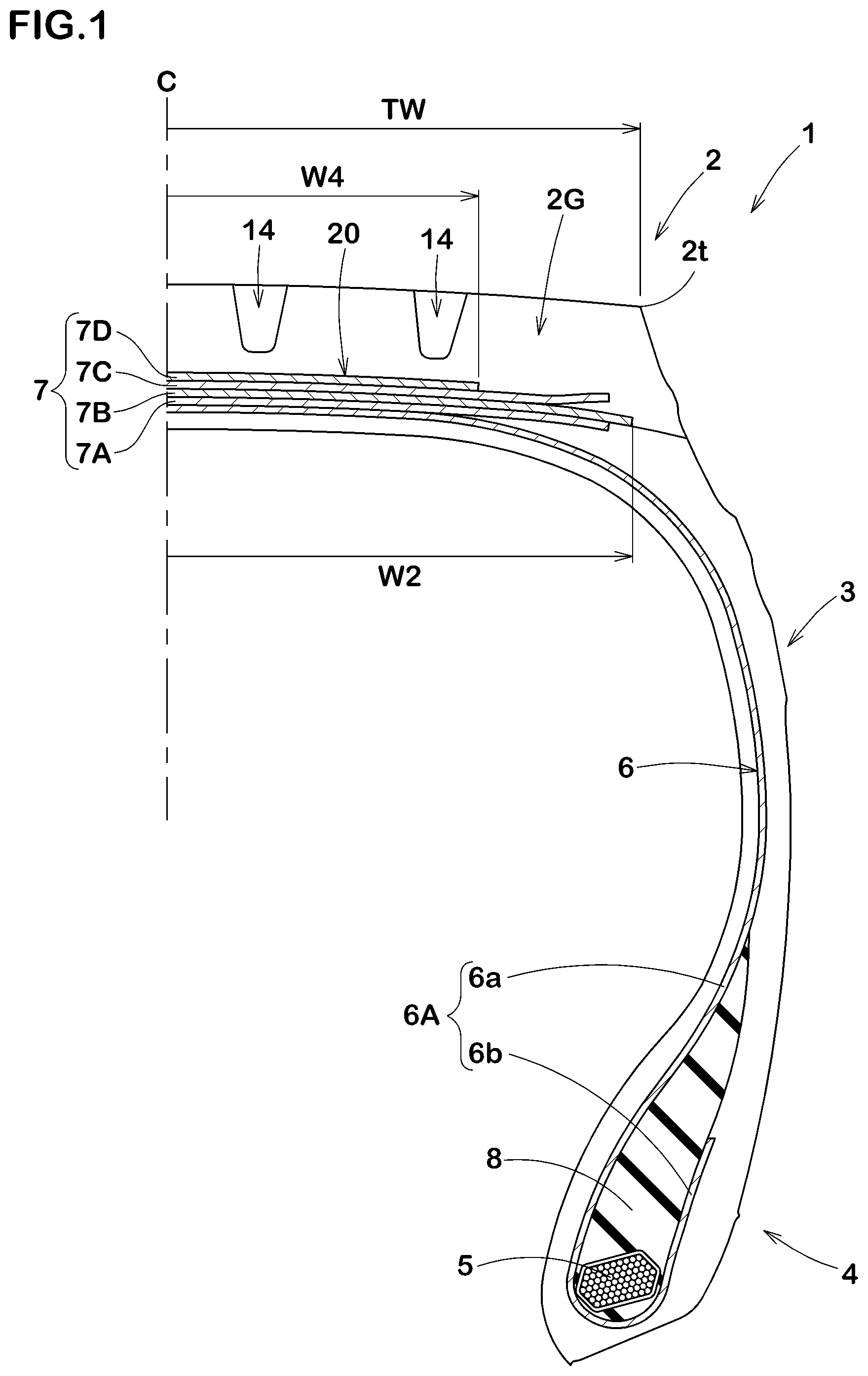
shows a meridian cross section including the tire rotation axis (not shown), of a right half of a heavy-duty tire 1 (hereinafter, may be simply referred to as the tire 1 ). The tire 1 in the present embodiment is designed for use with, for example, a truck or a bus.
The tire 1 in the present embodiment comprises: a tread portion 2 ; a pair of axially spaced bead portions 4 each with a bead core 5 therein; a pair of sidewall portions 3 extending between tread edges 2 t and the bead portions 4 ; a carcass 6 extending between the bead cores 5 in the bead portions 4 through the tread portion 2 and the sidewall portions 3 ; and a tread reinforcing belt 7 disposed radially outside the carcass 6 in the tread portion 2 .
Here, the tread edges 2 t are the axial outermost edges of the ground contacting patch of the tire which occurs under a normally inflated loaded state when the camber angle of the tire is zero.
The undermentioned tread width TW is the width measured under a normally inflated unloaded state, as the axial distance between the tread edges 2 t determined as above.
The normally inflated unloaded state is such that the tire is mounted on a standard wheel rim and inflate to a standard pressure but loaded with no tire load.
The normally inflated loaded state is such that the tire is mounted on the standard wheel rim and inflated to the standard pressure and loaded with a standard tire load.
The standard wheel rim is a wheel rim officially approved or recommended for the tire by standards organizations, i.e. JATMA (Japan and Asia), T&RA (North America), ETRTO (Europe), TRAA (Australia), STRO (Scandinavia), ALAPA (Latin America), ITTAC (India) and the like which are effective in the area where the tire is manufactured, sold or used.
The standard pressure and the standard tire load are the maximum air pressure and the maximum tire load for the tire specified by the same organization in the Air-pressure/Maximum-load Table or similar list.
For example, the standard wheel rim is the “standard rim” specified in JATMA, the “Measuring Rim” in ETRTO, the “Design Rim” in TRA or the like.
The standard pressure is the “maximum air pressure” in JATMA, the “Inflation Pressure” in ETRTO, the maximum pressure given in the “Tire Load Limits at Various Cold Inflation Pressures” table in TRA or the like.
The standard tire load is the “maximum load capacity” in JATMA, the “Load Capacity” in ETRTO, the maximum value given in the above-mentioned table in TRA or the like.
In this application including specification and claims, various dimensions, positions and the like of the tire refer to those under the normally inflated unloaded state of the tire unless otherwise noted.
[Tread Portion]
The tread portion 2 is provided with a tread rubber 2 G disposed on the radially outer side of the belt 7 . The tread rubber 2 G is provided with main grooves 14 extending in the tire circumferential direction. The main grooves 14 are recessed inward in the tire radial direction from the radially outer surface of the tread portion 2 .
[Carcass]
The carcass 6 is composed of at least one, in the present embodiment, only one carcass ply 6 A. The carcass ply 6 A extends between the bead portions 4 through the tread portion 2 and the sidewall portions 3 and is turned up around the bead core 5 in each bead portion 4 so as to form a pair of turned up portions 6 b and a main portion 6 a therebetween.
Each of the bead portions 4 is provided, between the turned up portion 6 b and the main portion 6 a , with a rubber bead apex 8 extending radially outwardly from the bead core 5 .
The carcass ply 6 A is composed of carcass cords (not shown), for example, arranged radially at an angle of 75 to 90 degrees with respect to the tire equatorial plane C. As the carcass cords, for example, steel cords can be suitably used.
[Belt]
As shown in , for example, the belt 7 is composed of a plurality of belt plies each composed of parallel belt cords 11 covered with a topping rubber 12 .
In the present embodiment, each belt cord 11 is made of a plurality of steel filaments (not shown) twisted together. The belt cords 11 is not limited to such a structure formed from the twisted steel filaments, and may be a single steel filament, for example.
In the present embodiment, as shown in , the belt 7 is composed of a first belt ply 7 A, a second belt ply 7 B, a third belt ply 7 C and a fourth belt ply 7 D arranged in this order from the inside to the outside in the tire radial direction.
In the present embodiment, as shown in , among the first belt ply 7 A to the fourth belt ply 7 D, the second belt ply 7 B has a largest axial width W 2 , and the fourth belt ply 7 D has a smallest axial width W 4 .
is a development view of the belt, wherein the belt cords 11 are shown in a simplified manner, and some of them are omitted.
As shown in , each of the first to fourth belt plies 7 A to 7 D is composed of parallel belt cords 11 inclined at an angle (θ 1 , θ 2 , θ 3 , θ 4 ) with respect to the tire equatorial plane C. In the present embodiment, the belt cords 11 of the first belt ply 7 A and the belt cords 11 of the second belt ply 7 B are inclined with respect to the tire equatorial plane C to one side in the tire axial direction, and
•
• the belt cords 11 of the third belt ply 7 C and the belt cords 11 of the fourth belt ply 7 D are inclined with respect to the tire equatorial plane C to the other side in the tire axial direction.
The angle θ 1 of the belt cords 11 of the first belt ply 7 A with respect to the tire equatorial plane C is set to a value between the angle θ 2 of the belt cords 11 of the second belt ply 7 B with respect to the tire equatorial plane C, and the above-mentioned angle of the carcass cords (not shown) of the carcass ply 6 A. Such first belt ply 7 A can increase the rigidity of the belt, while alleviating the shear strain caused between the carcass ply 6 A and the second belt ply 7 B, and can further reinforce the tread portion 2 .
In order to effectively enhance such function, it is preferable that the angle θ 1 is set in a range from 30 to 60 degrees.
The belt cords 11 of the second belt ply 7 B cross the belt cords 11 of the third belt ply 7 C. Such second belt ply 7 B and third belt ply 7 C can increase the binding force in the tire circumferential direction, therefore, the second belt ply 7 B and the third belt ply 7 C can firmly reinforce the tread portion 2 with its hoop effect, and can improve the durability performance.
It is preferable that the angle θ 2 of the belt cords 11 of the second belt ply 7 B with respect to the tire equatorial plane C is set in a range from 15 to 25 degrees, and the angle θ 3 of the belt cords 11 of the third belt ply 7 C with respect to the tire equatorial plane C is set in a range from 15 to 25 degrees.
By setting the angles θ 2 and θ 3 to not more than 25 degrees, the tread portion 2 can be firmly reinforced and the durability performance can be improved.
By setting the angles θ 2 and θ 3 to not less than 15 degrees, it is possible to prevent the binding force in the tire circumferential direction from becoming unnecessarily large, so the riding comfort can be maintained.
From such viewpoints, the angles θ 2 and θ 3 are preferably not more than 22 degrees, and preferably not less than 18 degrees.
As shown in , the fourth belt ply 7 D is located on the outermost side in the tire radial direction in the belt 7 in order to improve the cut resistance of the tread portion 2 .
As shown in , a first distance L 1 is set to be not more than a second distance L 2 , wherein
•
• the first distance L 1 is a distance in the tire radial direction between the belt cords 11 of the third belt ply 7 C and the belt cords 11 of the fourth belt ply 7 D, and • the second distance L 2 is a distance in the tire radial direction between the belt cords 11 of the second belt ply 7 B and the belt cords 11 of the third belt ply 7 C. • Each of the first distance L 1 , the second distance L 2 and the undermentioned third distance L 3 may be defined by an average value of the distance between the belt cords 11 adjacent in the tire radial direction, which is averaged over the entire width of a region 20 where all of the first to fourth belt plies 7 A to 7 D overlap in the tire radial direction, in other words, all of the first to fourth belt plies 7 A to 7 D exist. In the present embodiment, such region 20 corresponds to a region having the width W 4 (shown in ) of the narrowest fourth belt ply 7 D.
In the tire 1 of the present embodiment, as the first distance L 1 is not more than the second distance L 2 , it is possible to prevent the amount of rubber (topping rubber 12 ) constituting the fourth belt ply 7 D from becoming relatively increased.
The fourth belt ply 7 D affects the rolling resistance performance of the tire as compared with the first to third belt plies 7 A to 7 C disposed radially inside the fourth belt ply 7 D. Therefore, in the tire 1 of the present embodiment, as the first distance L 1 is set to not more than the second distance L 2 , an increase in energy loss of the belt 7 (fourth belt ply 7 D) can be prevented, and thereby, the rolling resistance performance is maintained. Further, since it is possible to prevent an increase in the amount of rubber (topping rubber 12 ) of the fourth belt ply 7 D, it is possible to suppress an increase in the mass of the tire 1 .
It is preferable that the first distance L 1 is set in a range from 80% to 100% of the second distance L 2 .
By setting the first distance L 1 to not more than 100% of the second distance L 2 , the rolling resistance performance can be maintained.
By setting the first distance L 1 to not less than 80% of the second distance L 2 , it is possible to suppress the belt cord loosening and separation from the rubber, and the durability performance can be maintained.
From such viewpoints, the first distance L 1 is preferably not more than 95% of the second distance L 2 , and preferably not less than 85% of the second distance L 2 .
The fourth belt ply 7 D has a smaller effect on the airtightness (air retention) of the tire inner cavity as compared with the first belt ply 7 A to the third belt ply 7 C. Therefore, even if the first distance L 1 is set smaller than the second distance L 2 , the airtightness of the inner cavity of the tire 1 can be maintained.
The first distance L 1 can be appropriately set as long as the above relationship with the second distance L 2 is maintained.
In the present embodiment, it is preferable that the first distance L 1 is set in a range from 0.4 to 1.0 mm.
By setting the first distance L 1 to not more than 1.0 mm, the rolling resistance performance can be maintained.
By setting the first distance L 1 to not less than 0.4 mm, it is possible to suppress a decrease in the cut resistance of the fourth belt ply 7 D, and the durability performance can be maintained.
From such viewpoints, the first distance L 1 is preferably not more than 0.8 mm, and preferably not less than 0.6 mm.
In the present embodiment, the third distance L 3 , which is the distance in the tire radial direction between the belt cords 11 of the second belt ply 7 B and the belt cords 11 of the first belt ply 7 A, is set to be the same as the second distance L 2 . Thereby, the reduction in the amount of rubber (topping rubber 12 ) constituting the first belt ply 7 A and the second belt ply 7 B can be maintained, so the airtightness (air retention) of the tire inner cavity can be maintained. In the present specification, the “same” means to include slight variations (errors) in manufacturing.
In the present embodiment, the cord count E 4 of the fourth belt ply 7 D is set to be smaller than the cord count E 3 of the third belt ply 7 C.
Here, the cord count is the number of the belt cords 11 per a unit ply width. The unit ply width is a length measured, in the meridian cross section of the tire under its normally inflated unloaded state, along the belt ply for which the number of the belt cords is counted.
In this embodiment, the unit ply width is 50 mm.
In the present embodiment, as the fourth belt ply's cord count E 4 is smaller than the third belt ply's cord count E 3 , the fourth belt ply 7 D can be reduced in the belt cords 11 while being increased in the rubber (topping rubber 12 ) covering the belt cords 11 . Thereby, in the fourth belt ply 7 D, the adhesion between the belt cords 11 and the rubber can be improved, so the belt cord loosening and separation from the rubber can be suppressed. Therefore, the tire 1 can be improved in the durability performance (cord loosening resistance performance).
In the present embodiment, since the fourth belt ply's cord count E 4 is smaller than the third belt ply's cord count E 3 , even when the first distance L 1 is not more than the second distance L 2 , the adhesion between the belt cords 11 of the fourth belt ply 7 D and the rubber can be increased. Therefore, in the tire 1 of the present embodiment, it is possible to maintain the rolling resistance performance and improve the durability performance.
It is preferable that the fourth belt ply's cord count E 4 is set in a range from 65% to 85% of the third belt ply's cord count E 3 .
By setting the fourth belt ply's cord count E 4 to not more than 85% of the third belt ply's cord count E 3 , the cord loosening of the fourth belt ply 7 D can be effectively prevented, and the durability performance can be improved.
By setting the fourth belt ply's cord count E 4 to not less than 65% of the third belt ply's cord count E 3 , it is possible to prevent the belt cords 11 from becoming less than necessary, so the rolling resistance performance and the cut resistance performance can be maintained. From such viewpoints, the fourth belt ply's cord count E 4 is preferably not more than 80% of the third belt ply's cord count E 3 , and preferably not less than 70% of the third belt ply's cord count E 3 .
In the present embodiment, the cord count E 1 of the first belt ply 7 A and the cord count E 2 of the second belt ply 7 B are set to be the same as the cord count E 3 of the third belt ply 7 C. Thereby, the first belt ply 7 A to the third belt ply 7 C can firmly reinforce the tread portion 2 , and can improve the durability performance.
With respect to the cord count per 50 mm ply width, the first belt ply's cord count E 1 to the fourth belt ply's cord count E 4 can be appropriately set as long as the above relationships are satisfied.
For example, the fourth belt ply's cord count E 4 may be set in a range from 12 to 22 cords per 50 mm ply width, and the first belt ply's cord count E 1 to the third belt ply's cord count E 3 may be set in a range from 19 to 27 cords per 50 mm ply width.
The belt cords 11 of the fourth belt ply 7 D have a cord diameter D 4 .
The belt cords 11 of the third belt ply 7 C have a cord diameter D 3 .
Preferably, the cord diameter D 4 is not more than the cord diameter D 3 .
Thereby, the fourth belt ply 7 D can be increased in the rubber (topping rubber 12 ) covering the belt cords 11 while being reduced in the belt cords 11 .
Thereby, the cord loosening of the fourth belt ply 7 D can be prevented, and the durability performance of the tire 1 can be improved.
Incidentally, when the belt cord 11 is formed from the twisted steel filaments, the cord diameter can be defined as the diameter of a circle circumscribing the bundle of the steel filaments.
It is preferable that the fourth belt ply's cord diameter D 4 is set in a range from 65% to 100% of the third belt ply's cord diameter D 3 .
By setting the fourth belt ply's cord diameter D 4 to not more than 100% of the third belt ply's cord diameter D 3 , it is possible to prevent the cord loosening of the fourth belt ply 7 D and improve the durability performance.
By setting the fourth belt ply's cord diameter D 4 to not less than 65% of the third belt ply's cord diameter D 3 , it is possible to prevent the belt cords 11 from becoming less than necessary, so the rolling resistance performance and the cut resistance performance can be maintained.
From such viewpoints, the fourth belt ply's cord diameter D 4 is preferably not more than 90% of the third belt ply's cord diameter D 3 , and preferably not less than 75% of the third belt ply's cord diameter D 3 .
The belt cords 11 of the first belt ply 7 A have a cord diameter D 1 .
The belt cords 11 of the second belt ply 7 B have a cord diameter D 2 .
In the present embodiment, the cord diameter D 1 and the cord diameter D 2 are set to be the same as the cord diameter D 3 of the third belt ply 7 C. Thereby, the first belt ply 7 A to the third belt ply 7 C can firmly reinforce the tread portion 2 and improve the durability performance.
As shown in , it is preferable that the angle θ 4 of the belt cords 11 of the fourth belt ply 7 D with respect to the tire equatorial plane C is set in a range from 30 to 60 degrees.
By setting the angle θ 4 to not less than 30 degrees, the tire 1 rolling under load can be deformed such that, while the annular tread portion maintains its original circular shape (namely, not deformed), its center is displaced downward in the tire radial direction from the tire rotational axis.
Thus, the strain generated in the fourth belt ply 7 D during tire rolling can be reduced. Therefore, cord loosening in the fourth belt ply 7 D can be prevented, and the durability performance can be improved.
On the other hand, by setting the angle θ 4 to not more than 60 degrees, the cut resistance can be maintained.
From such viewpoints, the angle θ 4 is preferably not less than 40 degrees, and preferably not more than 50 degrees.
It is preferable that, as shown in , the shortest distance L 4 in the tire radial direction between each main groove 14 and the belt cords 11 of the fourth belt ply 7 D is set in a range from 3 to 7 mm.
By setting the shortest distance L 4 to not less than 3 mm, the adhesion between the belt cords 11 and the tread rubber 2 G can be improved. Thereby, it is possible to prevent cord loosening of the fourth belt ply 7 D, and improve the durability performance of the tire 1 . On the other hand, by setting the shortest distance L 4 to not more than 7 mm, it is possible to prevent an increase in energy loss in the tread rubber 2 G and the fourth belt ply 7 D. Therefore, it is possible to maintain the rolling resistance performance.
From such viewpoints, the shortest distance L 4 is preferably not less than 4 mm, and preferably not more than 6 mm.
It is preferable that, as shown in , the axial width W 4 of the fourth belt ply 7 D is set in a range from 25% to 75% of the tread width TW.
By setting the fourth belt ply's axial width W 4 to not more than 75% of the tread width TW, the amount of rubber (topping rubber 12 ) constituting the fourth belt ply 7 D is reduced. Thereby, an increase in the energy loss of the fourth belt ply 7 D is prevented, and the rolling resistance performance of the tire can be improved.
On the other hand, by setting the fourth belt ply's axial width W 4 to not less than 25% of the tread width TW, the cut resistance can be maintained.
From such viewpoints, the fourth belt ply's axial width W 4 is preferably not more than 60% of the tread width TW, and preferably not less than 40% of the tread width TW.
While detailed description has been made of a preferable embodiment of the present disclosure, the present disclosure can be embodied in various forms without being limited to the illustrated embodiment.
Comparison Tests
Embodiment A
Heavy-duty tires having the internal structure shown in and specifications shown in Table 1 were experimentally manufactured as test tires (Working examples Ex. 1 to Ex. 9 and Comparative example Ref). Then, each tire was tested for the durability performance (drum test, presence or absence of belt cord separation), durability performance (plunger test), and rolling resistance performance.
The common specifications are as follows.
•
• Tire size: 275/80R22.5 • Rim size: 8.25×22.5 • Tire pressure: 900 kPa • Tire load: 28.8 kN • Tread width TW: 240 mm • Slip angle: 0 degrees • First belt ply:
• belt cord angle θ 1 : 50 degrees • cord count E 1 : 19 cords per 50 mm ply width • first distance L 1 : 0.5 mm • Second belt ply and third belt ply:
• belt cord angles θ 2 and θ 3 : 15 degrees • cord counts E 2 and E 3 : 27 cords per 50 mm ply width • Fourth belt ply:
• belt cord angle θ 1 : 50 degrees • shortest distance L 4 from main groove: 4.0 mm • axial width W 4 /tread width TW: 40% <Durability Performance (Drum Test, Belt Cord Separation)>
Each test tire was mounted on a wheel rim of the above-mentioned size, and inflated to the above-mentioned tire pressure. Then, using a drum-type tire tester, each test tire was run under the above-mentioned tire load and slip angle, and the running speed was increased gradually from the initial speed of 80 km/h at a step of 10 km/h every two hours after the start of running to obtain the running time until the tire was broken.
The results are shown in Table 1 by an index based on Working example Ex. 3 being 100, wherein the larger value is better, and when the value is 95 or more, it is considered that the durability performance (resistance to cord loosening) required for heavy-duty tires is secured.
In addition, the broken test tire was disassembled, and checked for the presence or absence of separation (cord loosening) caused at the interface between the belt cords and the tread rubber.
<Durability Performance (Plunger test)>
Each test tire was mounted on a wheel rim of the above-mentioned size, and inflated to the above-mentioned tire pressure. Then, a plunger test according to Japanese Industrial Standards D4230 was performed to determine the tire plunger energy required to completely penetrate the tread portion.
The results are shown in Table 1 by an index based on Working example Ex. 3 being 100, wherein the larger value is the better, and when the value is 95 or more, it is considered that the cut resistance required for heavy-duty tires is secured.
<Rolling Resistance Performance>
Each test tire was mounted on a wheel rim of the above-mentioned size, and inflated to the above-mentioned tire pressure. Then, using a tire rolling resistance tester, the rolling resistance was measured at the running speed of 60 km/h under the above-mentioned tire load.
The results are shown in Table 1 by an index based on Working example Ex. 3 being 100, wherein the smaller value is the better, and when the value is 105 or less, it is considered that the rolling resistance performance required for heavy-duty tires is secured.
TABLE 1
Tire Ref. Ex. 1 Ex. 2 Ex. 3 Ex. 4
first distance L1/second 100 100 100 100 100
distance L2 (%)
cord count E4/cord count 100 90 85 74 65
E3 (%)
durability (drum test) 90 97 99 100 102
belt cord separation yes no no no no
durability (plunger test) 102.5 102 101 100 99
rolling resistance 97 98 99 100 101
Tire Ex. 5 Ex. 6 Ex. 7 Ex. 8 Ex. 9
first distance L1/second 100 95 85 80 75
distance L2 (%)
cord count E4/cord count 60 74 74 74 74
E3 (%)
durability (drum test) 103 99 98 97 95
belt cord separation no no no no no
durability (plunger test) 97 99 98 97 96
rolling resistance 103 99 97 96 95
From the test results, it was confirmed that, as compared with Comparative example Ref. Working examples were improved in the durability while maintaining the rolling resistance performance.
Embodiment B
Heavy-duty tires having the internal structure shown in and specifications shown in Table 2 were experimentally manufactured as test tires (Working examples Ex. 3 and Ex. 10 to Ex. 18). Then, each tire was tested for the durability performance (drum test, presence or absence of belt cord separation), durability performance (plunger test), and rolling resistance performance.
The common specifications are the same as those of Embodiment A except for the following specifications and the specifications shown in Table 2.
•
• first distance L 1 /second distance L 2 : 100% • fourth belt ply's cord count E 4 /third belt ply's cord count E 3 : 74% • fourth belt ply's cord diameter D 4 : 1.0 mm
The test methods are as described in Embodiment A and the test results are shown in Table 2.
TABLE 2
Tire Ex. 3 Ex. 10 Ex. 11 Ex. 12 Ex. 13
cord diameter D4/cord 100 90 75 65 60
diameter D3 (%)
angle θ4 (degrees) 40 40 40 40 40
durability (plunger test) 100 102 103 104 105
belt cord separation no no no no no
durability (plunger test) 100 99 98 97 95
rolling resistance 100 101 102 103 105
Tire Ex. 14 Ex. 15 Ex. 16 Ex. 17 Ex. 18
cord diameter D4/cord 100 100 100 100 100
diameter D3 (%)
angle θ4 (degrees) 25 30 50 60 65
durability (plunger test) 96 99 101 102 103
belt cord separation no no no no no
durability (plunger test) 102 101 97.5 97 95
rolling resistance 98 99 101 102 103
From the test results, it was confirmed that, as compared with Working example Ex. 13 in which the fourth belt ply's cord diameter D 4 /the third belt ply's cord diameter D 3 was outside the preferable range,
Working examples Ex. 3 and Ex. 10 to Ex. 12 in which the fourth belt ply's cord diameter D 4 /the third belt ply's cord diameter D 3 was within the preferable range were improved in the durability (cord loosening resistance), while maintaining the rolling resistance performance and durability (cut resistance).
Further, in Working examples Ex. 3 and Ex. 15 to Ex. 17 in which the angle θ 4 of the fourth belt ply was within the preferable range,
•
• the deterioration of the rolling resistance performance and durability performance (cutting resistance performance) was suppressed, and the durability performance (cord loosening resistance) was improved, • as compared with Working examples Ex. 14 and Ex. 18 in which the angle θ 4 was outside the preferable range.
Embodiment C
Heavy-duty tires having the internal structure shown in and specifications shown in Table 3 were experimentally manufactured as test tires (Working examples Ex. 3 and Ex. 19 to Ex. 28). Then, each tire was tested for the durability performance (drum test, presence or absence of belt cord separation), durability performance (plunger test), and rolling resistance performance.
The common specifications are the same as those of Embodiment A except for the following specifications and the specifications shown in Table 3.
•
• first distance L 1 /second distance L 2 : 100% • fourth belt ply's cord count E 4 /third belt ply's cord count E 3 : 74%
The test methods are as described in Embodiment A, and the test results are shown in Table 3.
TABLE 3
Tire Ex. 3 Ex. 19 Ex. 20 Ex. 21 Ex. 22 Ex. 23
shortest distance L4 (mm) 4.0 2.5 3.0 6.0 7.0 8.0
fourth belt ply width W4/ 40 40 40 40 40 40
tread width TW (%)
durability (drum test) 100 95 100 105 106 106
belt cord separation no no no no no no
durability (plunger test) 100 95 99 105 106 106
rolling resistance 100 96 98 101 102 104
Tire Ex. 24 Ex. 25 Ex. 26 Ex. 27 Ex. 28
shortest distance L4 (mm) 4.0 4.0 4.0 4.0 4.0
fourth belt ply width W4/ 20 25 60 75 80
tread width TW (%)
durability (drum test) 99 100 101 101 102
belt cord separation no no no no no
durability (plunger test) 97.5 99 102 103 103
rolling resistance 98 99 101 102 104
From the test results, it was confirmed that, as compared with Working examples Ex. 19 and Ex. 23 in which the shortest distance L 4 was outside the preferable range, Working examples Ex. 3, Ex. 20 and Ex. 22 in which the shortest distance L 4 was within the preferable range were improved in the durability performance (cord loosening resistance) while maintaining the rolling resistance performance.
Further, as compared with Working examples Ex. 24 and Ex. 28 in which the fourth belt ply's axial width W 4 /tread width TW was outside the preferable range,
Working examples Ex. 3 and Ex. 25 to Ex. 27 in which the fourth belt ply's axial width W 4 /tread width TW was within the preferable range were improved in the durability performance (cut resistance), while maintaining the rolling resistance performance.
Statement of the Present Disclosure
The present disclosure is as follows:—
Disclosure 1: A heavy-duty tire comprising: a tread portion, a pair of axially spaced bead portions each with a bead core therein, a pair of sidewall portions extending between the tread edges and the bead portions, a carcass extending between the bead cores in the bead portions through the tread portion and the sidewall portions, and a tread reinforcing belt disposed radially outside the carcass in the tread portion.
•
• wherein
• the belt comprises a first belt ply, a second belt ply, a third belt ply and a fourth belt ply which are arranged in this order from the carcass side toward the outside in the tire radial direction, and • each of the first to fourth belt plies is composed of belt cords inclined with respect to the tire equatorial plane, • wherein
• a first distance L 1 in the tire radial direction between the belt cords of the third belt ply and the belt cords of the fourth belt ply is not more than a second distance L 2 in the tire radial direction between the belt cords of the second belt ply and the belt cords of the third belt ply, and • with respect to a cord count of a belt ply which is the number of the belt cords per unit width of the belt ply, a cord count E 4 of the fourth belt ply is smaller than a cord count E 3 of the third belt ply.
Disclosure 2: The heavy-duty tire according to claim 1 , wherein the cord count E 4 of the fourth belt ply is in a range from 65% to 85% of the cord count E 3 of the third belt ply.
Disclosure 3: The heavy-duty tire according to claim 1 or 2 , wherein the first distance L 1 is in a range from 80% to 100% of the second distance L 2 .
Disclosure 4: The heavy-duty tire according to claim 1 , 2 or 3 , wherein the belt cords of the fourth belt ply have a cord diameter D 4 , the belt cords of the third belt ply have a cord diameter D 3 , and the cord diameter D 4 is in a range from 65% to 100% of the cord diameter D 3 .
Disclosure 5: The heavy-duty tire according to claim 1 , 2 , 3 or 4 , wherein the belt cords of the fourth belt ply are inclined at an angle in a range from 30 to 60 degrees with respect to the tire equatorial plane.
Disclosure 6: The heavy-duty tire according to any one of claims 1 to 5 , wherein the tread portion is provided with a main groove extending in the tire circumferential direction, and a shortest distance in the tire radial direction between the belt cords of the fourth belt ply and the bottom of the main groove is in a range from 3 to 7 mm,
Disclosure 7: The heavy-duty tire according to any one of claims 1 to 6 , wherein the belt cords of the first belt ply are inclined at an angle in a range from 30 to 60 degrees with respect to the tire equatorial plane,
•
• the belt cords of the second belt ply are inclined at an angle in a range from 15 to 25 degrees with respect to the tire equatorial plane, and • the belt cords of the third belt ply are inclined at an angle in a range from 15 to 25 degrees with respect to the tire equatorial plane.
Disclosure 8: The heavy-duty tire according to any one of claims 1 to 7 , wherein the width in the tire axial direction, of the fourth belt ply is in a range from 25% to 75% of a tread width.
DESCRIPTION OF THE REFERENCE SIGNS
•
• 1 heavy-duty tire • 7 belt • 7 A first belt ply • 7 B second belt ply • 7 C third belt ply • 7 D fourth belt ply • 11 belt cord
Figures (3)
Citations
This patent cites (6)
- US4890658
- US5318643
- US20090095396
- US849098
- US2013-184637
- US2020-63051