Glass Fastening and Sealing Systems
Abstract
A glass fastening system includes a glass portion, a support structure defining a recess, a first adhesive layer disposed on an exterior surface of the glass portion facing the recess in the support structure, a second adhesive layer disposed within the recess of the support structure, and a fastener having a first portion secured to the first adhesive layer and a second portion extending away from the first portion and into the second adhesive layer to secure the glass portion to the support structure.
Claims (20)
1. A glass fastening system, comprising: a glass portion; a support structure defining a recess; an overmold secured to a side surface of the glass portion and an exterior surface of the glass portion that faces the support structure; a retainer disposed within the recess of the support structure; a fastener having a fastener head secured to the exterior surface of the glass portion by and within the overmold at a location spaced from the side surface of the glass portion and a fastener shaft protruding from the overmold, extending away from the fastener head, and extending into the retainer to secure the glass portion to the support structure; and a gap defined between an exterior surface of the overmold and a top of the retainer, wherein the fastener shaft is exposed within the gap and extends across the gap between the overmold and the retainer, wherein the retainer includes an adhesive that secures the glass portion to the support structure via the fastener shaft.
3. The glass fastening system, wherein the adhesive is compliant, compressibly securing the glass portion.
9. A glass fastening system, comprising: a glass portion; a support structure defining a recess; an adhesive disposed within the recess of the support structure; and a fastener having a fastener head secured to the glass portion via an overmold and a fastener shaft extending away from the fastener head and into the adhesive to secure the glass portion to the support structure, wherein a gap separates the overmold and the adhesive and allows access to the fastener shaft to support removal of the fastener when the glass portion is secured to the support structure.
14. A glass fastening system, comprising: first and second glass portions; a support structure; first and second recesses defined in the support structure; first and second retainers disposed within the first and second recesses of the support structure; first and second fasteners having fastener heads secured to the first and second glass portions via first and second overmolds and fastener shafts extending away from the fastener heads and into the first and second retainers to secure the first and second glass portions to the support structure; a first gap defined between the first and second glass portions that separates side surfaces of the first and second overmolds; and a second gap defined between the first and second overmolds and the first and second retainers, wherein the second gap provides access to the fastener shafts of the first and second fasteners to support removal of the first and second fasteners when the first and second glass portions are secured to the support structure.
Show 16 dependent claims
2. The glass fastening system of claim 1 , wherein the gap provides access to the fastener shaft between the overmold and the support structure to allow removal of the fastener from the support structure.
4. The glass fastening system of claim 3 , wherein the adhesive fills an entirety of the recess in the support structure.
5. The glass fastening system of claim 1 , wherein the overmold is secured only to the side surface of the glass portion and the exterior surface of the glass portion that faces the support structure.
6. The glass fastening system of claim 1 , wherein the overmold obscures the fastener shaft and the retainer from a view looking through the glass portion toward the support structure.
7. The glass fastening system of claim 1 , wherein the retainer includes a bushing disposed in the recess and configured to receive the fastener shaft of the fastener.
8. The glass fastening system of claim 1 , wherein the glass portion is a laminated glass portion comprising a first glass pane, a second glass pane, and an interlayer disposed therebetween.
10. The glass fastening system of claim 9 , wherein the adhesive is compliant and compressibly secures the glass portion to the support structure via the fastener shaft.
11. The glass fastening system of claim 9 , wherein the overmold is secured to only a side surface of the glass portion and an exterior surface of the glass portion that faces the support structure.
12. The glass fastening system of claim 9 , wherein the overmold obscures the adhesive from a view looking through the glass portion toward the support structure.
13. The glass fastening system of claim 9 , wherein the glass portion is a laminated glass portion comprising a first glass pane, a second glass pane, and an interlayer disposed therebetween.
15. The glass fastening system of claim 14 , wherein the first and second retainers include an adhesive that is compliant and compressibly secures the first and second glass portions to the support structure via the fastener shafts of the first and second fasteners.
16. The glass fastening system of claim 15 , wherein the adhesive fills an entirety of the first and second recesses in the support structure.
17. The glass fastening system of claim 16 , wherein the first and second overmolds obscure the adhesive from a view looking through the first and second glass portions toward the support structure.
18. The glass fastening system of claim 14 , wherein the first and second retainers include first and second bushings disposed in first and second recesses, and wherein the first and second bushings are configured to receive the fastener shafts of the first and second fasteners.
19. The glass fastening system of claim 14 , wherein the first and second glass portions are laminated glass portions comprising first glass panes, second glass panes, and interlayers disposed therebetween.
20. The glass fastening system of claim 14 , wherein the first and second overmolds are secured only to side surface of the first and second glass portions and exterior surfaces of the first and second glass portions that face the support structure.
Full Description
Show full text →
CROSS-REFERENCE TO RELATED APPLICATIONS
This application is a continuation of U.S. patent application Ser. No. 16/745,571, filed on Jan. 17, 2020, which is a divisional of U.S. patent application Ser. No. 15/437,996, filed on Feb. 21, 2017, which claims the benefit of U.S. Provisional Application No. 62/298,143, filed on Feb. 22, 2016, each of which is incorporated by reference in its entirety.
TECHNICAL FIELD
The application relates generally to joints for glass. More particularly, described embodiments relate to overmolds, seals, masks, and fasteners that are joined with laminated glass during or after the lamination process.
BACKGROUND
Laminated glass, or safety glass, is traditionally formed by bonding either a polyvinyl butyral (PVB) or ethylene-vinyl acetate (EVA) interlayer between two layers of glass. A thin film or layer of PVB or EVA can be placed between two layers of glass, a vacuum can be applied to remove air from between the various layers, and then heat and/or pressure can be applied to bond the layers together, for example, using an autoclave. Laminated glass can be used to dampen sound transmission and increase the level of safety in architectural and automotive applications, for example, to deter shattering of windows during a hurricane or dampen sound entering through the windows of a passenger compartment of a vehicle.
Traditional fastening systems for laminated glass include edge-style frames and c-shaped or u-shaped clamps that surround panes of laminated glass as well as spider-style fittings attached to bore-based fasteners configured to position the corners of multiple pieces of laminated glass adjacent to each other. More elegant fastening solutions are needed to minimize visibility of the fastening system.
SUMMARY
The disclosure relates to glass fastening and sealing systems. In one aspect of the disclosure, a glass fastening system includes a first glass pane, a second glass pane defining a bore, an interlayer disposed between and extending along interior surfaces of the first glass pane and the second glass pane, and a fastener having a first portion disposed along the interlayer between the first glass pane and the second glass pane and a second portion extending outward from an exterior surface of the second glass pane.
In another aspect of the disclosure, a glass fastening system includes a first glass pane, a second glass pane, an interlayer disposed between the glass panes, an adhesive layer disposed along an exterior surface of the second glass pane, and a fastener having a first portion extending along the adhesive layer and a second portion extending from the first portion and away from the exterior surface. The second portion of the fastener is configured to secure the first glass pane and the second glass pane to a support structure.
In another aspect of the disclosure, a glass sealing system includes a first glass portion having a first edge portion, a second glass portion having a second edge portion, an interlayer disposed between the first glass portion and the second glass portion, and a seal comprising an overmold portion capturing the first edge portion and the second edge portion.
In another aspect of the disclosure, a glass sealing system includes a first glass pane, a second glass pane defining a recessed portion and a plurality of bores within the recessed portion, an interlayer disposed between the first glass pane and the second glass pane, and a seal. The seal includes an internal portion extending along and disposed within the recessed portion, an external portion axially aligned with the internal portion and extending along an exterior surface of the second glass pane, and connection portions extending through the bores from the internal portion to the external portion.
BRIEF DESCRIPTION OF THE DRAWINGS
The disclosure will be readily understood by the following detailed description in conjunction with the accompanying drawings, wherein like reference numerals designate like structural elements. A description of the drawings is as follows.
shows a top view of laminated glass including a fastening system.
shows an exploded sectional view of a fastener embedded in a portion of the laminated glass of during glass lamination.
shows an exploded sectional view of another fastener embedded in a portion of the laminated glass of during glass lamination.
shows an exploded sectional view of another fastener adhered to a portion of the laminated glass of .
shows a top view of laminated glass including another type of fastening system.
shows an exploded sectional view of a fastener extending through a portion of the laminated glass of .
shows a top view of a juncture for two portions of laminated glass including another type of fastening system.
shows an exploded sectional view of a fastener for clamping the two portions of laminated glass of .
shows a top view of a sealing juncture for two portions of laminated glass with at least one portion movable in respect to the other portion.
shows an exploded sectional view of the sealing juncture of with seals embedded during glass lamination.
shows a sectional view of laminated glass sections disposed within a ductile, structural overmold.
shows a top view of another sealing juncture for two portions of laminated glass adhered to a support structure.
shows a sectional view of the sealing juncture of with masks embedded during glass lamination.
shows a sectional view of the sealing juncture of with overlapping covers adhered to the glass for adhesion to the support structure.
shows a sectional view of the sealing juncture of with spaced covers adhered to the glass for adhesion to the support structure.
shows a sectional view of the sealing juncture of with fasteners extending from the laminated glass into the support structure.
shows a sectional view of the sealing juncture of with fasteners extending from an overmold into the support structure.
shows a top view of another sealing juncture for two portions of laminated glass with at least one portion movable in respect to the other portion.
shows a sectional view of the sealing juncture of with an overmolded seal disposed on one of the glass portions.
shows a sectional view of the sealing juncture of with another overmolded seal disposed on one of the glass portions.
DETAILED DESCRIPTION
The following disclosure relates to glass fastening systems, sealing systems, and support structures. In some examples of fastening systems, fastener portions are embedded between glass panes during a glass lamination process. In other examples of fastening systems, fastener portions are adhered to exterior surfaces of glass panes or magnetically attracted to each other through glass panes. In examples of sealing systems, seals are partially embedded within or encapsulated around edges of laminated glass portions, either during or after the lamination process. In examples of support structures, transparent, ductile support bodies extend between overmold portions to capture and support laminated glass portions.
The glass fastening and sealing systems described below can be implemented in automotive applications, for example, to increase the transparent area of glass surfaces in a vehicle such as the windshield, door windows, backlight, or roof. Embedded fasteners can be used to attach laminated glass directly to underlying body structure, such as an A-, B-, or C-pillar in a vehicle. Embedded or encapsulated seals can be used to abut portions of laminated glass, for example, at a door window to a windshield or a backlight interface, allowing more of the interface to be transparent. Supporting laminated glass portions within a transparent, ductile body can also increase the transparent area of various glass vehicle surfaces.
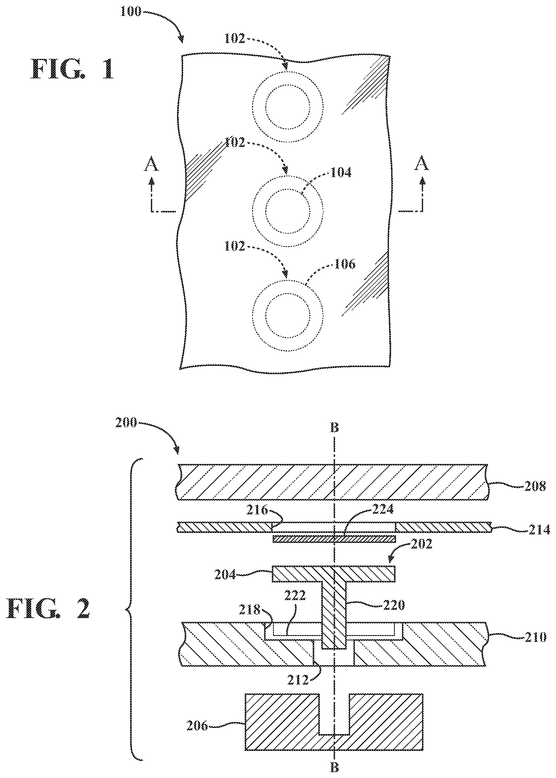
shows a top view of laminated glass 100 including an example of a fastening system. As seen in the top view, multiple fasteners 102 are included in the fastening system, each including a fastener portion 104 embedded within or adhered to the laminated glass 100 and a fastener portion 106 configured to couple with the embedded or adhered fastener portion 104 , for example, in association with a structure to which the laminated glass 100 is connected, such as a vehicle pillar or a door frame. A section, A-A, is shown as extending through a central fastener 102 in the fastening system. Sectional views through section A-A for various examples of the fastener 102 are described in conjunction with below.
shows an exploded sectional view of a fastener 202 embedded in a laminated glass portion 200 during the lamination process. The laminated glass portion 200 can be part of the laminated glass 100 of . The sectional view of laminated glass portion 200 includes a first glass pane 208 and a second glass pane 210 . The second glass pane 210 defines a bore 212 . The laminated glass portion 200 also includes an interlayer 214 defining another bore 216 , the bore 216 in the interlayer 214 being axially aligned with the bore 212 in the second glass pane 210 , for example, along axis B. The interlayer 214 is disposed between the first glass pane 208 and the second glass pane 210 and extends along interior surfaces of the first glass plane 208 and the second glass pane 210 so as to couple the first and second glass panes 208 , 210 . The interlayer 214 can include a pressure-based adhesive and/or a thermally-activated adhesive configured to join the first glass pane 208 and the second glass pane 210 during the lamination process.
The fastener 202 in the laminated glass fastening system of includes a fastener portion 204 disposed at least partially within the bore 216 in the interlayer 214 once the lamination process is complete. The second glass pane 210 can also include a relief portion 218 formed, for example, by grinding or machining. The relief portion 218 is configured both to avoid an increase in thickness in the laminated glass portion 200 and to assist in locating the fastener portion 204 before the lamination process. Thus, the fastener portion 204 becomes captured, or sandwiched, between the first glass pane 208 and the second glass pane 210 once lamination is complete. The fastener 202 also includes a fastener portion 220 extending from the fastener portion 204 and through the bore 212 in the second glass pane 210 . The fastener portion 220 can extend below a bottom surface of the second glass pane 210 after the lamination process is complete.
The fastener 202 also includes a fastener portion 206 configured to capture the fastener portion 220 that extends through the bore 212 beyond the bottom surface of the second glass pane 210 . In this example, the fastener portion 206 is a female portion and the fastener portion 220 is a male portion, though other configurations are also possible. The fastener portion 206 can be disposed in, extend through, or generally be associated with a structure such that connection of the fastener portion 220 with the fastener portion 206 couples the laminated glass portion 200 to the underlying structure.
The lamination process can include placing a compliant layer 222 between the fastener portion 204 and the relief portion 218 of the second glass pane 210 . The compliant layer 222 can be deformable and configured to dissipate clamp loads between the fastener 202 and the second glass pane 210 since machining or grinding the relief portion 218 can create additional stress on the laminated glass portion 200 . Though the compliant layer 222 is shown as located within the relief portion 218 , the fastener 202 could alternatively be designed to include the compliant layer 222 .
The lamination process for embedding the fastener 202 of can also include placing a conductive layer 224 between the first glass pane 208 and the fastener portion 204 , the conductive layer 224 being configured to transmit energy through the fastener 202 . In one example, the conductive layer 224 can be designed to collect solar energy. In another example, the conductive layer 224 can be designed to transmit electricity in order to power devices associated with the laminated glass portion 200 , such as lights, sensors, etc. In some cases, these devices can be part of the embedded fastener 202 .
shows an exploded sectional view of another fastener 302 embedded in a laminated glass portion 300 during the lamination process. The laminated glass portion 300 can be part of the laminated glass 100 of . The sectional view of the laminated glass portion 300 includes a first glass pane 308 and a second glass pane 310 . The laminated glass portion 300 also includes an interlayer 314 defining a bore 316 . The interlayer 314 is disposed between the first glass pane 308 and the second glass pane 310 and extends along interior surfaces of the first glass plane 308 and the second glass pane 310 so as to couple the first and second glass panes 308 , 310 . The interlayer 314 can include a pressure-based adhesive and/or a thermally-activated adhesive configured to join the first glass pane 308 and the second glass pane 310 during the lamination process.
The fastener 302 in the laminated glass fastening system of includes a fastener portion 304 disposed at least partially within the bore 316 in the interlayer 314 once the lamination process is complete. To aid in locating the fastener portion 304 during the lamination process and avoid an increase in overall thickness, the second glass pane 310 can include a relief portion 318 formed, for example, by grinding or machining. The fastener portion 304 becomes captured, or sandwiched, between the first glass pane 308 and the second glass pane 310 once lamination is complete, nestled within the bore 316 and the relief portion 318 .
The fastener 302 also includes a fastener portion 320 disposed on an exterior surface of the second glass pane 310 . The fastener portion 320 can be aligned with the fastener portion 304 after the lamination process is complete by having one of the fastener portion 304 and the fastener portion 320 formed of a magnetic material and the other of the fastener portion 304 and the fastener portion 320 formed of a magnetically attractable material, that is, the two fastener portions 304 , 320 are attracted magnetically.
The magnet, be it part of the fastener portion 304 or the fastener portion 320 , can be designed to have sufficient strength to allow the fastener portion 320 to be further coupled to the separate fastener portion 306 . The fastener portion 306 is configured to capture the fastener portion 320 . In this example, the fastener portion 306 is a female portion and the fastener portion 320 is a male portion, though other configurations are also possible. In a similar manner as described in respect to , the fastener portion 306 can be disposed in, extend through, or generally be associated with a structure such that connection of the fastener portion 320 with the fastener portion 306 couples the laminated glass portion 300 to the underlying structure.
shows an exploded sectional view of another fastener 402 adhered to a laminated glass portion 400 . The laminated glass portion 400 can be part of the laminated glass 100 of . The laminated glass portion 400 includes a first glass pane 408 , a second glass pane 410 , and an interlayer 414 disposed between the first glass pane 408 and the second glass pane 410 . As in previous examples, the interlayer 414 joins the first glass pane 408 and the second glass pane 410 during the lamination process. A fastener 402 is attached to the second glass pane 410 using an adhesive 426 , the adhesive being disposed on an exterior surface of the second glass pane 410 . Alternatively, the adhesive 426 can be applied to the fastener 402 before attachment to the laminated glass portion 400 .
Specifically, the fastener 402 includes a fastener portion 404 that is disposed on and extends for the length of the adhesive 426 and a fastener portion 420 extending away from the fastener portion 404 and away from an exterior surface of the second glass pane 410 . Optionally, the fastener portion 404 can include, comprise, or be contained within a glass housing 428 , or at least formed of a glass material. In this example, the adhesive 426 connects two glass surfaces together. Using a glass housing 428 or a glass material in association with the fastener portion 404 provides additional structure and strength to the fastener 402 while at the same time minimizing stress to the laminated glass portion 400 and maintaining transparency.
The fastener 402 can also include a fastener portion 406 configured to capture the fastener portion 420 . In this example, the fastener portion 406 is a female portion and the fastener portion 420 is a male portion, though other configurations are also possible. In a similar manner as described in respect to , the fastener portion 406 can be disposed in, extend through, or generally be associated with a structure such that connection of the fastener portion 420 with the fastener portion 406 couples the laminated glass portion 400 to the underlying structure.
shows a top view of laminated glass 500 including another type of fastening system. As seen in this top view, multiple fasteners 502 are included in the fastening system, portions of the fasteners 502 being present on a top surface of the laminated glass 500 . A section, C-C, is shown as extending through a central fastener 502 in the fastening system. A sectional view along section C-C through a fastener similar to one of the fasteners 502 is described in conjunction with below.
shows an exploded sectional view of a fastener 602 extending through a laminated glass portion 600 . The laminated glass portion 600 can be part of the laminated glass 500 of . The laminated glass portion 600 includes a first glass pane 608 having a relief portion 618 and defining a bore 630 , a second glass pane 610 defining a bore 612 , and an interlayer 614 defining a bore 616 . The bores 612 , 616 , 630 are axially aligned and the interlayer 614 is disposed between the first glass pane 608 and the second glass pane 610 .
The fastener 602 includes a fastener portion 604 at least partially disposed within the relief portion 618 within the first glass pane 608 and a fastener portion 620 extending from the fastener portion 604 through all three bores 612 , 616 , 630 . The fastener 602 also includes a fastener portion 606 configured to capture the fastener portion 620 . In , the fastener portion 620 is shown as a male portion and the fastener portion 606 is shown as a female portion, though other configurations are possible. For example, the fastener portion 606 can at least partially extend through the bore 612 to capture the fastener portion 620 . The fastener portion 606 can extend from or be captured within a support structure, such as a vehicle pillar or a door frame.
In operation, the laminated glass portion 600 can be machined, drilled, bored, etc. either before or after the lamination process, and the fastener portion 606 can be associated with or make contact with an underlying structure in order to join the laminated glass portion 600 to the structure. In the example of , the fastener portion 604 is designed so as to be flush with an outer surface of the first glass pane 608 after connection of the laminated glass portion 600 to the structure.
shows a top view of a juncture for two laminated glass portions 700 a,b including another type of fastening system. As seen in the top view, multiple fasteners 702 are included in the fastening system, portions of the fasteners 702 being present on a top surface of a trim element 732 used to clamp the two laminated glass portions 700 a,b together. A section, D-D, is shown as extending through a central fastener 702 in the fastening system. A sectional view through section D-D of a fastener similar to one of the fasteners 702 is described in conjunction with below.
shows an exploded sectional view of a fastener 802 for clamping two laminated glass portions 800 a,b together. The laminated glass portions 800 a,b can be part of or similar to the laminated glass portions 700 a,b of . The laminated glass portions 800 a,b each include first glass panes 808 a,b , second glass panes 810 a,b , and interlayers 814 a,b . Both laminated glass portions 800 a,b also include recess portions 818 a,b on upper surfaces. A trim element 832 is disposed within the recess portions 818 a,b . In a manner similar to that shown for the trim element 732 of , the trim element 832 of can extend for most of the length of the two laminated glass portions 800 a,b in order to define a clamping surface against the two laminated glass portions 800 a,b.
The trim element 832 also defines a bore 834 , the bore 834 being configured to receive the fastener 802 . The fastener 802 in includes a fastener portion 804 that is disposed along an upper surface of the trim element 832 and a fastener portion 820 that extends from the fastener portion 804 through the bore 834 and along side surfaces of the two laminated glass portions 800 a,b . The fastener 802 also includes a fastener portion 806 configured to capture the fastener portion 820 and clamp the two laminated glass portions 800 a,b together in conjunction with the trim element 832 . The trim element 832 can also include a recess portion (not shown) such that the fastener portion 804 sits within the recess portion of the trim element 832 once the clamp load is applied.
In , the fastener portion 820 is shown as a male portion and the fastener portion 806 is shown as a female portion, though other fastening schemes are also possible. In this example, the fastener portion 806 is also designed to extend along the side surfaces of the two laminated glass portions 800 a,b when it captures the fastener portion 820 . Again, the fastener portion 806 can be associated with, captured within, or extend from an underlying structure such as a vehicle pillar or a door frame such that the fastening system clamps the two laminated glass portions 800 a,b to the underlying structure using the trim element 832 .
shows a top view of a sealing juncture for two laminated glass portions 900 a,b with at least one portion 900 a movable in respect to the other portion 900 b . Each of the laminated glass portions 900 a,b includes an embedded seal 936 a,b . The seals 936 a,b include internal portions 938 a,b , external portions 940 a,b , and a plurality of connection portions 942 a,b that extend from the internal portions 938 a,b to the external portions 940 a,b of the seals 936 a,b . The sealing juncture is designed such that the external portion 940 a can couple with the external portion 940 b when the two laminated glass portions 900 a,b are brought together, for example, in the case of moving window in the door of a vehicle. A section, E-E, is shown as extending through a pair of central connection portions 942 a,b in the sealing system. A sectional view through section E-E for a connection portion similar to the central connection portions 942 a,b is described in conjunction with below.
shows an exploded sectional view of the sealing juncture of . Each of the laminated glass portions 1000 a,b in includes a first glass pane 1008 a,b , a second glass pane 1010 a,b , and an interlayer 1014 a,b disposed between the first and second glass panes 1008 a,b , 1010 a,b . The second glass panes 1010 a,b define recessed portions 1018 a,b and bores 1012 a,b . The recessed portions 1018 a,b can extend along the length of the second glass panes 1010 a,b and the bores 1012 a,b can be multiple and spaced along the recessed portions 1018 a,b at predetermined intervals.
The laminated glass sealing system of can include a pair of seals 1036 a,b . The seals 1036 a,b can include internal portions 1038 a,b that extend along and are disposed within the recessed portions 1018 a,b . The seals 1036 a,b can also include external portions 1040 a,b that are axially aligned with the internal portions 1030 a,b and extend along an exterior surface of the second glass panes 1010 a,b . In this example, the external portions 1040 a,b also extend beyond the sides of the second glass panes 1010 a,b , forming lips or edges for the seals 1036 a,b outside of the second glass panes 1010 a,b.
The seals 1036 a,b can also include multiple connection portions 1042 a,b , the connection portions 1042 a,b extending through the bores 1012 a,b from the internal portions 1038 a,b to the external portions 1040 a,b . The seals 1036 a,b can be located prior to lamination, for example, by passing the external portions 1040 a,b through the bores 1012 a,b . Alternatively, the seals 1036 a,b can be applied to the laminated glass portions 1000 a,b after the lamination process, for example, using injection molding or another process configured to force the material of the seals into the recessed portions 1018 a,b through the bores 1012 a,b.
In operation of the sealing system of , the two external portions 1040 a,b can be engaged by sliding the laminated glass portions 1000 a,b toward each other in the same plane. In this example, the external portion 1040 a is a male portion and the external portion 1040 b is a female portion, though other coupling schemes are also possible. The laminated glass sealing system of also includes a set of masks 1044 a,b disposed between the first glass panes 1008 a,b and the interlayers 1014 a,b , the masks 1044 a,b being axially aligned with the internal portions 1038 a,b of the seals 1036 a,b so as to block visibility of the seals 1036 a,b from an external surface of the first glass panes 1008 a,b . The masking feature is optional and serves to change the appearance of the laminated glass sealing system.
shows a sectional view of laminated glass portions 1100 a,b,c,d disposed within ductile, structural overmolds. In this example, the overmolds are support structures 1146 a,b,c,d including support bodies 1148 a,b,c,d extending between pairs of overmold sections 1150 a,b,c,d , with each of the overmold sections 1150 a,b,c,d capturing one end of the laminated glass portions 1100 a,b,c,d . Though the example of includes four laminated glass portions 1100 a,b,c,d and four support structures 1146 a,b,c,d coupled in a ring shape, other configurations are also possible.
The support structures 1146 a,b,c,d can be formed of a non-glass material, such as a composites or a polymer with transparent properties, making both the laminated glass portions 1100 a,b,c,d and the support structures 1146 a,b,c,d transparent. The support structures 1146 a,b,c,d can also be formed of a ductile material that allows deformation while at the same time providing sufficient stiffness to withstand outside forces acting upon the laminated glass portions 1100 a,b,c,d without bending or buckling. These outside forces can be caused, for example, by winds from weather events, by impact from other structures, etc.
shows a top view of another sealing juncture for two laminated glass portions 1200 a,b adhered to a support structure 1252 . The support structure 1252 can be, for example, a vehicle pillar, such as an a-pillar or a roof beam extending between a-pillars on a vehicle, or an architectural beam, such as a brace extending between a floor and a ceiling in a building. The sealing juncture can be designed such that an outer edge 1254 a of the laminated glass portion 1200 a is spaced from an outer edge 1254 b of the laminated glass portion 1200 b when the two laminated glass portions 1200 a,b are adhered to the support structure 1252 . The sealing juncture can also be designed such that both laminated glass portions 1200 a,b overlap an upper surface of the support structure 1252 to allow for build tolerance variation when securing the laminated glass portions 1200 a,b to the support structure 1252 . A section, F-F, is shown as extending through the laminated glass portions 1200 a,b and the support structure 1252 in the sealing system. Various sectional views through section F-F for a variety of sealing and attachments systems are described in conjunction with below.
shows a sectional view of the sealing juncture of with masks 1344 a,b embedded during glass lamination. The sealing juncture can include two glass portions 1300 a,b having first glass panes 1308 a,b , second glass panes 1310 a,b , and interlayers 1314 a,b . Though shown as laminated glass portions 1300 a,b , other forms of glass or other transparent materials are also possible. Adhesive layers 1326 a,b , for example, in the form of a thick, curable, compliant adhesive such as urethane, can be disposed on exterior surfaces of the glass portions 1300 a,b in order to secure the glass portions 1300 a,b to a support structure 1352 . In the example of , the adhesive layers 1326 a,b are positioned near outer edges 1354 a,b of the glass portions 1300 a,b such that the adhesive layers 1326 a,b can be compressed against the support structure 1352 and, for example, cured or dried, in order to firmly secure the glass portions 1300 a,b to the support structure 1352 .
When being secured to the support structure 1352 , the outer edges 1354 a,b of the glass portions 1300 a,b are generally aligned while at the same time slightly spaced in order to avoid contact between the outer edges 1354 a,b . Additionally, a sufficient amount of overlap is designed between the glass portions 1300 a,b and the support structure 1352 such that build variation in the support structure 1352 or placement of the adhesive layers 1326 a,b does not impact sealing of the adhesive layers 1326 a,b to the support structure 1352 . Once the glass portions 1300 a,b are secured to the support structure 1352 , the visual effect becomes one of floating glass, with both the support structure 1352 and the adhesive layers 1326 a,b visible through the glass portions 1300 a,b.
In the case where viewing the adhesive layers 1326 a,b is not desirable or the adhesive requires isolation from solar radiation, the glass portions 1300 a,b can be designed with integrated masks 1344 a,b , for example, of a color or style matching, coordinating with, or otherwise complementing the support structure 1352 or other design features of the overall structure in which the glass portions 1300 a,b are installed. The masks 1344 a,b can be laminated between the respective glass panes 1308 a,b , 1310 a,b or can be applied to an exterior surface of the glass portions 1300 a,b . When applied, the masks 1344 a,b are designed for axial alignment with the adhesive layers 1326 a,b such that the adhesive layers 1326 a,b are not visible through the glass portions 1300 a,b . The masks 1344 a,b can include any number of colors, materials, or design features so as to both cover the adhesive layers 1326 a,b and provide a pleasing visual effect.
shows a sectional view of the sealing juncture of with overlapping covers 1456 a,b adhered to glass portions 1400 a,b for adhesion to an underlying support structure 1452 . The sealing juncture can include two glass portions 1400 a,b having first glass panes 1408 a,b , second glass panes 1410 a,b , and interlayers 1414 a,b . Though shown as laminated glass portions 1400 a,b , other forms of glass or other transparent materials are also possible. Thin, transparent adhesive layers 1458 a,b can be applied to exterior surfaces of the glass portions 1400 a,b in order to secure the covers 1456 a,b to the glass portions 1400 a,b . The transparent adhesive layers 1458 a,b can be designed with little or no compliance in order to rigidly secure the covers 1456 a,b to the glass portions 1400 a,b.
The covers 1456 a,b in the example of are elongated panels having opposing surfaces, the first surfaces being secured to the transparent adhesive layers 1458 a,b , and the second or opposing surfaces being configured to receive compliant adhesive layers 1426 a,b similar to the adhesive layers 1326 a,b described in reference to . The covers 1456 a,b can be shaped in variety of ways or formed from a variety of materials, such as plastic, steel, aluminum, or composite, so as to create a desired visual effect when viewed from either side of the glass portions 1400 a,b . The covers 1456 a,b are designed to extend beyond outer edges 1454 a,b of the glass portions 1400 a,b when secured by the transparent adhesive layers 1458 a,b to obscure the support structure 1452 from view through one side of the glass portions 1400 a,b.
Once the compliant adhesive layers 1426 a,b are applied to the covers 1456 a,b , the glass portions 1400 a,b can be positioned such that the extending portions of the covers 1456 a,b either meet or overlap, and the combination of the glass portions 1400 a,b and the covers 1456 a,b can be compressed against the support structure 1452 to complete the sealing juncture. When the glass portions 1400 a,b are secured to the support structure 1452 , the covers 1456 a,b extend from opposing edges of the support structure 1452 to positions beyond the outer edges 1454 a,b of the glass portions 1400 a,b , completely obscuring the compliant adhesive layers 1426 a,b from view from either side of the glass portions 1400 a,b.
shows a sectional view of the sealing juncture of with spaced covers 1556 a,b adhered to glass portions 1500 a,b for adhesion to an underlying support structure 1552 . The sealing juncture can include two glass portions 1500 a,b having first glass panes 1508 a,b , second glass panes 1510 a,b , and interlayers 1514 a,b . Though shown as laminated glass portions 1500 a,b , other forms of glass or other transparent materials are also possible. Transparent adhesive layers 1558 a,b can be applied to exterior surfaces of the glass portions 1500 a,b in order to secure the covers 1556 a,b to the glass portions 1500 a,b . The transparent adhesive layers 1558 a,b can be designed to be thin, with little or no compliance, or to be thicker, having some compliance. In either design, the transparent adhesive layers 1558 a,b can firmly secure the covers 1556 a,b to the glass portions 1500 a,b.
The covers 1556 a,b in the example of are c-shaped channels having opposing surfaces, the first surfaces being secured to the transparent adhesive layers 1558 a,b , and the second or opposing surfaces being configured to receive compliant adhesive layers 1526 a,b . The shape of the covers 1556 a,b allows the channels to be filled with the compliant adhesive layers 1526 a,b . The support structure 1552 can be designed with recesses 1560 a,b configured to receive the covers 1556 a,b filled with the compliant adhesive layers 1526 a,b , that is, the covers 1556 a,b can be inserted, at least partially, within the recesses 1560 a,b in the support structure 1552 . To secure the glass portions 1500 a,b to the support structure 1552 , the compliant adhesive layers 1526 a,b that fill the channels in the covers 1556 a,b can be compressed against bottom surfaces of the recesses 1560 a,b in the support structure 1552 .
Though the covers 1556 a,b in are shown as protruding slightly from the recesses 1560 a,b when the sealing juncture is complete, the covers 1556 a,b can be designed to be flush with the top of the recesses 1560 a,b or to protrude further from the recesses 1560 a,b when installed. In any of these configurations, the covers 1556 a,b can completely obscure the compliant adhesive layers 1526 a,b from view while at the same time providing a striped visual effect when viewed from one side of the glass portions 1500 a,b . The location of the recesses 1560 a,b in the support structure 1552 can modify the visual effect. Additionally, the recesses 1560 a,b can be shaped such that the compliant adhesive layer 1526 a,b can be removed when necessary, for example, using a thin angled tool, such as a vehicle trim tool in the case where the support structure 1552 is a vehicle pillar.
shows a sectional view of the sealing juncture of with fasteners 1602 a,b extending from glass portions 1600 a,b into a support structure 1652 . The sealing juncture can include two glass portions 1600 a,b having first glass panes 1608 a,b , second glass panes 1610 a,b , and interlayers 1614 a,b . Though shown as laminated glass portions 1600 a,b , other forms of glass or other transparent materials are also possible. Transparent adhesive layers 1658 a,b can be applied to exterior surfaces of the glass portions 1600 a,b in order to secure first portions 1604 a,b of the fasteners 1602 a,b to the glass portions 1600 a,b . The transparent adhesive layers 1658 a,b can be designed to be thin, with little or no compliance, in order to rigidly secure the first portions 1604 a,b to the glass portions 1600 a,b.
The fasteners 1602 a,b in the example of include both the first portions 1604 a,b secured to the transparent adhesive layers 1658 a,b and second portions 1620 a,b extending from the respective first portions 1604 a,b away from the transparent adhesive layers 1658 a,b . The support structure 1652 can be designed with bores or recesses 1660 a,b configured to receive the second portions 1620 a,b of the fasteners 1602 a,b . In one embodiment, the recesses 1660 a,b in the support structure 1652 can be filled with compliant adhesive layers 1626 a,b configured to receive the second portions 1620 a,b of the fasteners 1602 a,b in order to secure the glass portions 1600 a,b to the support structure 1652 . In another embodiment (not shown) the recesses 1660 a,b can include other forms of retainers, such as bushings, configured to receive the second portions 1620 a,b of the fasteners 1602 a,b.
The first portions 1604 a,b of the fasteners 1602 a,b can be visible through the glass portions 1600 a,b and can be shaped or styled such that the second portions 1620 a,b of the fasteners 1602 a,b as well as the compliant adhesive layers 1626 a,b are obscured when viewed from one side of the glass portions 1600 a,b . The location of the fasteners 1602 a,b adhered to the glass portions 1600 a,b and the location of the recesses 1660 a,b in the support structure 1652 can be changed to modify the visual effect. The recesses 1660 a,b can be shaped such that the compliant adhesive layers 1526 a,b , and in turn, the second portions 1620 a,b of the fasteners 1602 a,b can be removed when necessary, for example, using a thin angled tool, such as a vehicle trim tool.
shows a sectional view of the sealing juncture of with fasteners 1702 a,b extending from overmolds 1750 a,b into a support structure 1752 . The sealing juncture can include two glass portions 1700 a,b having first glass panes 1708 a,b , second glass panes 1710 a,b , and interlayers 1714 a,b . Though shown as laminated glass portions 1700 a,b , other forms of glass or other transparent materials are also possible. The overmolds 1750 a,b can be applied, for example, using an encapsulation process, to edges 1754 a,b of the glass portions 1700 a,b . The overmolds 1750 a,b can be designed to secure first portions 1704 a,b of the fasteners 1702 a,b to the glass portions 1700 a,b and create a visual feature along the edges 1754 a,b.
The fasteners 1702 a,b in the example of include both the first portions 1704 a,b embedded or captured within the overmolds 1750 a,b and second portions 1720 a,b extending perpendicularly from the first portions 1704 a,b out of the overmolds 1750 a,b . The support structure 1752 can be designed with bores or recesses 1760 a,b configured to receive the second portions 1720 a,b of the fasteners 1702 a,b . In the example of , the recesses 1760 a,b can be designed to hold or receive retainers, such as bushings 1762 a,b , configured to capture the second portions 1720 a,b of the fasteners 1702 a,b . Though the retainers shown are bushings 1762 a,b , other forms of retainers such as clips, adhesives, or clamps are also possible.
The first portions 1704 a,b of the fasteners 1702 a,b can be visible through the glass portions 1700 a,b and can be positioned within the overmolds 1750 a,c as desired to modify the visual effect of the fasteners 1702 a,b . The interface between the overmolds 1750 a,b and the support structure 1752 can be designed such that the second portions 1720 a,b of the fasteners 1702 a,b can be removed from the support structure 1752 when necessary, for example, by designing a gap between the overmolds 1750 a,b and the support structure 1752 when the fasteners 1702 a,b are secure. In the embodiment shown in , the fasteners 1702 a,b are located at discrete points within the overmold 1750 a,b . In an alternative embodiment (not shown), the second portions 1720 a,b of the fasteners 1702 a,b can be located at discrete points while the first portions 1704 a,b of the fasteners 1702 a,b are formed as strips or bars, creating a striped effect when viewed through the glass portions 1700 a,b.
shows a top view of another sealing juncture for two glass portions 1800 a,b with one glass portion 1800 a movable in respect to the other glass portion 1800 b . The glass portions 1800 a,b include first edge portions 1864 a,b and second edge portions 1866 a,b that are offset from the first edge portions 1864 a,b . The sealing juncture is designed such that the when the glass portion 1800 a moves toward the glass portion 1800 b , the first edge portions 1864 a,b align and the second edge portions 1866 a,b align when the two glass portions 1800 a,b are brought together, for example, in the case of a moving window in the door of a vehicle. A section, G-G, is shown as extending through the glass portions 1800 a,b in the sealing system. Various sectional views through section G-G for a variety of sealing systems are described in conjunction with below.
shows a sectional view of the sealing juncture of with an overmolded seal 1936 disposed between glass portions 1900 a,b . Each of the glass portions 1900 a,b in includes a first glass pane 1908 a,b , a second glass pane 1910 a,b , an interlayer 1914 a,b disposed between the first and second glass panes 1908 a,b , 1910 a,b , and edges 1954 a,b defining first edge portions 1964 a,b offset from second edge portions 1966 a,b . The offset of the first edge portion 1964 a and the second edge portion 1966 a is in the opposite direction from the offset of the first edge portion 1964 b and the second edge portion 1966 b such that the two glass portions 1900 a,b can align in an interlocking manner when one moves toward the other. The offset is beneficial, for example, in situations where pressure differentials inside and outside of the sealing juncture pull the edges 1954 a,b of the glass portions 1900 a,b apart, such as in a vehicle traveling at higher speeds.
The seal 1936 in can include an overmold portion 1968 that captures the first edge portion 1964 b and the second edge portion 1966 b of the glass portion 1900 b , for example, by encapsulation. The seal 1936 can also include a compressible portion that extends from the overmold portion 1968 . In this example, the compressible portion includes a first bulb portion 1970 configured to sealingly engage the first edge portions 1964 a,b of the glass portions 1900 a,b under compression and a second bulb portion 1972 configured to sealingly engage the second edge portions 1966 a,b of the glass portions 1900 a,b and the support structure 1952 under compression. In operation of the sealing system of , the glass portions 1900 a,b can be sealed against the support structure 1952 by sliding the glass portion 1900 a toward the glass portion 1900 b . Once slid together, the first edge portion 1964 a of the glass portion 1900 a engages the first bulb portion 1970 and the second edge portion 1966 a of the glass portion 1900 a engages the second bulb portion 1972 . The second bulb portion 1972 is compressed in a manner which in turn engages the support structure 1952 as shown.
shows a sectional view of the sealing juncture of with another overmolded seal 2036 disposed between glass portions 2000 a,b . Each of the glass portions 2000 a,b in includes a first glass pane 2008 a,b , a second glass pane 2010 a,b , an interlayer 2014 a,b disposed between the first and second glass panes 2008 a,b , 2010 a,b , and edges 2054 a,b defining first edge portions 2064 a,b offset from second edge portions 2066 a,b . The offset of the first edge portion 2064 a and the second edge portion 2066 a is in the opposite direction from the offset of the first edge portion 2064 b and the second edge portion 2066 b such that the two glass portions 2000 a,b can align in an interlocking manner when one moves toward the other, as was described in reference to .
The seal 2036 in can include an overmold portion 2068 that captures the first edge portion 2064 b and the second edge portion 2066 b of the glass portion 2000 b , for example, by encapsulation. The seal 2036 can also include a pair of compressible portions that extend from the overmold portion 2068 . In this example, a first bulb portion 2070 is configured to sealingly engage the first edge portions 2064 a,b of the glass portions 2000 a,b under compression and a second bulb portion 2072 is configured to sealingly engage the second edge portions 2066 a,b of the glass portions 2000 a,b under compression. To guide the glass portions 2000 a,b together and to seal the glass portions 2000 a,b to the support structure 2052 , the sealing system includes another seal 2074 disposed on the support structure 2052 . In operation, the glass portions 2000 a,b can be sealed against the support structure 2052 by sliding the glass portion 2000 a toward the glass portion 2000 b . Once slid together, the first edge portion 2064 a of the glass portion 2000 a engages the first bulb portion 2070 and the second edge portion 2066 a engages the second bulb portion 2072 . The second glass pane 2010 a also compresses the seal 2074 attached to the support structure 2052 .
Figures (11)
Citations
This patent cites (371)
- US2061760
- US2125372
- US2257951
- US2302740
- US2359163
- US2403060
- US2858414
- US2936050
- US3425176
- US3427776
- US3868804
- US3967424
- US3968612
- US4072340
- US4093304
- US4219230
- US4277294
- US4292774
- US4311336
- US4364595
- US4500572
- US4543283
- US4543755
- US4551372
- US4552790
- US4571278
- US4581276
- US4606159
- US4635415
- US4645146
- US4650240
- US4680206
- US4691489
- US4723809
- US4738065
- US4793112
- US4799344
- US4799346
- US4817347
- US4839122
- US4861540
- US4879853
- US4891732
- US4893443
- US4905432
- US4905435
- US4933032
- US4938521
- US4994315
- US5014934
- US5027567
- US5042871
- US5057354
- US5062248
- US5085021
- US5095669
- US5137770
- US5138804
- US5152650
- US5170602
- US5185979
- US5199236
- US5261718
- US5300171
- US5301484
- US5331784
- US5381637
- US5384995
- US5391411
- US5391416
- US5398452
- US5421130
- US5429858
- US5475956
- US5493831
- US5503684
- US5519979
- US5522636
- US5524404
- US5527083
- US5540514
- US5544458
- US5592795
- US5601328
- US5620794
- US5635281
- US5676898
- US5711119
- US5723196
- US5760744
- US5787662
- US5804719
- US5806257
- US5851470
- US5864996
- US5935356
- US5988730
- US6086138
- US6120274
- US6136122
- US6136427
- US6138434
- US6179940
- US6209946
- US6220650
- US6235984
- US6254397
- US6309755
- US6316099
- US6347491
- US6412225
- US6609350
- US6811857
- US6862851
- US7000356
- US7040063
- US7553536
- US7960854
- US8427381
- US8810462
- US20010023562
- US20010030449
- US20020020119
- US20020031398
- US20020069590
- US20020092601
- US20020148255
- US20030057660
- US20040003555
- US20040006939
- US20040068943
- US20040145214
- US20040183413
- US20040251713
- US20050077683
- US20050144862
- US20050188634
- US20050221062
- US20060005482
- US20060099833
- US20060101737
- US20060157890
- US20060179786
- US20060260234
- US20060272227
- US20060292380
- US20070063539
- US20070071572
- US20070190282
- US20080053023
- US20080081148
- US20080213545
- US20090077921
- US20090174300
- US20090191375
- US20090260742
- US20090309391
- US20100024328
- US20100059253
- US20100166987
- US20100243047
- US20100294121
- US20120024349
- US20120129401
- US20120132245
- US20120159880
- US20120169196
- US20130033894
- US20130086855
- US20130140844
- US20130140847
- US20130214555
- US20130323481
- US20130327372
- US20130330495
- US20140007510
- US20140026502
- US20140079474
- US20140084119
- US20140178635
- US20140216526
- US20140230354
- US20140318058
- US20140327267
- US20150016132
- US20150024165
- US20150093539
- US20150300784
- US20160017596
- US20160221256
- US20160347377
- US20170009514
- US20170051778
- US20170218990
- US20170256872
- US20170298621
- US20180178482
- US20190390506
- US506530
- US2006228089
- US1197886
- US2252834
- US202106819
- US102802938
- US203022545
- US203035016
- US203198695
- US732014
- US1196330
- US7801989
- US3409831
- US3322442
- US3323006
- US3439436
- US3604389
- US3616468
- US3643472
- US3717428
- US3701808
- US3807459
- US3832178
- US4014200
- US4307634
- US4325024
- US29622574
- US19539960
- US19543192
- US29716365
- US19651649
- US19710824
- US19751124
- US19859888
- US19929480
- US10022250
- US19955639
- US10052529
- US10052538
- US10132356
- US10232609
- US10225140
- US20317939
- US10333978
- US202004017265
- US202006007201
- US102006027074
- US102006019210
- US102008023408
- US102008006553
- US102009020351
- US202009010065
- US102009033562
- US202011001267
- US102009044770
- US102010018935
- US102011015076
- US102011050752
- US102011102840
- US102011121031
- US202014005330
- US0128837
- US0163195
- US0297952
- US0319695
- US0340089
- US0367908
- US0368728
- US390151
- US0506522
- US526327
- US0611854
- US0623727
- US0695848
- US0795431
- US0882616
- US1297237
- US1388622
- US1447494
- US1449693
- US1754844
- US1865753
- US1881147
- US1905934
- US1908913
- US2006465
- US2014734
- US2147813
- US2339646
- US2485275
- US2583822
- US2190665
- US2692979
- US2857192
- US2577483
- US2630157
- US2655076
- US2657376
- US2732730
- US2739060
- US2746843
- US2777316
- US2927053
- US2974559
- US3002528
- US2024297
- US2095318
- US2290577
- USTV-20090186
- US58035416
- US60099769
- US59192615
- US62026115
- US62199525
- US63082814
- USH02254012
- USH08151239
- USH09170280
- USH09303338
- US2000177383
- US2001252943
- US2002096633
- US2002096634
- US2003039946
- US2005096658
- US2005320214
- US2005350290
- US2006175601
- US2006294646
- US2007039994
- US2007126067
- US2007177468
- US2013079066
- US2014104790
- US2014172497
- US2001057985
- US20030033300
- US20050014153
- US2007040487
- US100828460
- US101174651
- US101497455
- US20150052423
- US20150129381
- US2010013548
- US201203757
- US9622443
- US9626336
- US9717221
- USWO-9716325
- USWO-0142036
- US2004011755
- US2006135365
- US2008125737
- US2009029897
- US2010079142
- US2010121666
- US2013034978
- US2013053345
- US2014086914
- US2018112
- US2254013
- US2276605
- US3236922
- US3284412
- US5033565
- US5141027
- US5141152
- US6071693
- US6156071
- US6191269
- US6272350
- US6330583