Method of Manufacturing a Fishing Lure
Abstract
The mold apparatus disclosed herein is configured for simultaneous communication of a resin having a color and a complementary resin having a complementary color into a mold cavity without intermixing between the resin and the complementary resin in order to form an object wherein the color is essentially separated from the complementary color, in various aspects. In various aspects, the object formed by the mold apparatus may be configured as a fishing lure body, which is a molded portion of a fishing lure. The fishing lure body has a top and a bottom, and the top is of the color and the bottom is of the complementary color, in various aspects. Related methods and manufactures are disclosed.
Claims (8)
1. A method of manufacturing a fishing lure, comprising the steps of: a) forming a mold cavity by biasingly engaging a first mating surface of a first die with a complementary second mating surface of a complementary second die, the mold cavity being defined by a first cavity surface of a first cavity formed in the first die and a complementary second cavity surface of a complementary second cavity formed in the second die, the mold cavity partitioned in part into a first mold sub-cavity and a second mold sub-cavity by a first barrier extending forth from the first cavity surface toward a plane defined by the first mating surface and by a complementary second barrier extending forth from the second cavity surface toward a plane defined by the second mating surface, the first barrier and the second barrier being in spaced relation with one another; b) communicating fluidly a first resin having a first color into the first mold sub-cavity through a first passage; c) communicating fluidly a complementary second resin having a second color into the second mold sub-cavity through a complementary second passage; and d) curing the first resin and the second resin to form the fishing lure; e) wherein the first resin and the second resin have the same flow properties; f) wherein the first resin is communicated into the first mold sub-cavity and the second resin is communicated into the second mold sub-cavity in parallel flow paths at the same time and at the same flow rate; g) wherein the first barrier and the second barrier are operable to promote separation of the first resin from the second resin as the first resin flows through the first mold sub-cavity along the longitudinal length of the first barrier and the second barrier and the second resin flows through the second mold sub-cavity along a longitudinal length of the first barrier and the second barrier, thereby inhibiting intermixing of the first resin with the second resin such that the fishing lure has a distinct color divide formed between the first resin and the second resin that coincides with the gap between the first barrier and the second barrier.
5. A method of manufacturing a fishing lure, comprising the steps of: a) providing a mold apparatus, comprising: i) a first die that defines a first cavity having a first cavity surface comprising at least in part a negative impression of a portion of a first surface of the fishing lure to be molded; ii) a first barrier configured into the first cavity surface, the first barrier extends from the first cavity surface in gapped relation with a plane of a first mating surface of the first die and the first barrier extends longitudinally along at least portions of the first cavity surface comprising the negative impression of the portion of the first surface of the fishing lure to be molded; iii) a complementary second die that defines a complementary second cavity having a complementary second cavity surface formed as a negative impression of a portion of a second surface of the of the fishing lure to be molded; iv) a complementary second barrier configured into the second cavity surface, the second barrier extends from the second cavity surface in gapped relation with a plane of a complementary second mating surface of the second die, the second barrier extends longitudinally along at least portions of the second cavity comprising the negative impression of the portion of the second surface of the fishing lure to be molded, the second barrier being longitudinally aligned with the first barrier; v) a mold cavity formed by biased engagement between the first mating surface of the first die and the second mating surface of the second die, the mold cavity defined by the first cavity surface and the complementary second cavity surface, the mold cavity partitioned in part into a first mold sub-cavity and a second mold sub-cavity by the first barrier and the second barrier that are longitudinally aligned with one another; vi) a first passage in fluid communication with the first mold sub-cavity, the first passage defined at least in part by the first die to communicate fluidly a first resin having a first color into the first mold sub-cavity; and vii) a complementary second passage in fluid communication with the second mold sub-cavity to communicate fluidly a complementary second resin having a second color into the second mold sub-cavity, the second passage defined at least in part by the second die; b) communicating fluidly the first resin having the first color into the first mold sub-cavity through the first passage; c) communicating fluidly the second resin having the second color into the second mold sub-cavity through the second passage; and d) curing the first resin and the second resin thereby forming the fishing lure; e) wherein the first resin and the second resin have the same flow properties; f) wherein the first resin is communicated into the first mold sub-cavity and the second resin is communicated into the second mold sub-cavity in parallel flow paths at the same time and at the same flow rate; g) wherein the first barrier and the second barrier are operable to promote separation of the first resin from the second resin as the first resin flows through the first mold sub-cavity along the longitudinal length of the first barrier and the second barrier and the second resin flows through the second mold sub-cavity along the longitudinal length of the first barrier and the second barrier, thereby inhibiting intermixing of the first resin with the second resin such that the fishing lure has a distinct color divide formed between the first resin and the second resin that coincides with the gap between the first barrier and the second barrier.
Show 6 dependent claims
2. A method according to claim 1 , wherein the first resin is communicated into the first mold sub-cavity and the second resin is communicated into the second mold sub-cavity at substantially the same temperature and pressure.
3. A method according to claim 1 , wherein the first resin and the second resin comprise plastisol.
4. A method according to claim 1 , wherein the fishing lure has a Shore hardness in a range of from about 5 to about 80 on the Shore A scale.
6. A method according to claim 5 , wherein the first resin is communicated into the first mold sub-cavity and the second resin is communicated into the second mold sub-cavity at substantially the same temperature and pressure.
7. A method according to claim 5 , wherein the first resin and the second resin comprise plastisol.
8. A method according to claim 5 , wherein the fishing lure has a Shore hardness in a range of from about 5 to about 80 on the Shore A scale.
Full Description
Show full text →
FIELD OF THE INVENTION
This disclosure relates to apparatus for molding simultaneously an object having two colors separated from one another along a color divide and related methods and manufactures. The object may form a fishing lure body of a fishing lure in certain aspects.
BACKGROUND OF THE INVENTION
Fishing lure bodies of fishing lures may be designed to mimic at least portions of various prey. The prey, of course, attracts predators, so that the fishing lure attracts the predator by mimicking the prey. The prey may have two different colors. For example, a top portion of the prey that is generally oriented toward a water surface may have a color that camouflages the prey from predators looking down on the prey from above. The prey may, for example, include a bottom portion generally oriented away from the water surface that has another color that camouflages the prey from predators looking up toward the prey from below. In order to accurately mimic the prey per this example, the lure body should include two colors divided from one another just like the two colors of the prey. It may be desirable that the two colors of the fishing lure body are essentially separated from one another with little or no intermixing, for example, in order to accurately mimic the prey. However, it is difficult to achieve efficiently this separation of colors in a molded product.
Accordingly, there is a need for improved mold apparatus as well as related manufacturing methods for manufactures such as fishing lure bodies that include two colors separated from one another with little or no intermixing.
BRIEF SUMMARY OF THE INVENTION
These and other needs and disadvantages may be overcome by the apparatus, methods, and manufactures disclosed herein. Additional improvements and advantages may be recognized by those of ordinary skill in the art upon study of the present disclosure.
A mold apparatus, as disclosed herein, may include a die that defines a cavity having a cavity surface formed at least in part as a negative impression of a portion of an object surface of an object to be molded. A barrier is configured into the cavity surface, and the barrier extends from the cavity surface in gapped relation with a plane of a surface of the die, in various aspects. The barrier extends longitudinally along at least portions of the cavity surface comprising the negative impression of the portion of the object surface, in various aspects. The mold apparatus further includes a complementary die that defines a complementary cavity having a complementary cavity surface formed as a negative impression of another portion of the object surface of the object. A complementary barrier is configured into the complementary cavity surface, and the complementary barrier extends from the complementary cavity surface in gapped relation with a complementary plane of a complementary surface of the complementary die, in various aspects. The complementary barrier extends longitudinally along at least portions of the complementary cavity comprising the negative impression of the another portion of the object surface, in various aspects.
A mold cavity may be formed by biased engagement between the surface of the die and the complementary surface of the complementary die, with the mold cavity being defined by the cavity surface and the complementary cavity surface. The mold cavity is partitioned in part into a first mold sub-cavity and a second mold sub-cavity by the barrier and the complementary barrier that are longitudinally aligned with one another within the mold cavity, in various aspects.
A passage is in fluid communication with the first mold sub-cavity, with the passage being defined at least in part by the die to communicate fluidly a resin into the first mold sub-cavity. A complementary passage separated from the passage by a divider is in fluid communication with the second mold sub-cavity to communicate fluidly a complementary resin into the second mold sub-cavity, with the complementary passage being defined at least in part by the complementary die. The resin is fluidly communicated into the first mold sub-cavity from the passage simultaneously with fluid communication of the complementary resin into the second mold sub-cavity from the complementary passage, in various aspects.
A method of manufacture is disclosed herein that includes the step of forming a mold cavity by biasingly engaging a surface of a die with a complementary surface of a complementary die, with the mold cavity being defined by a cavity surface of a cavity formed in the die and a complementary cavity surface of a complementary cavity formed in the complementary die, in various aspects. The mold cavity is partitioned in part into a first mold sub-cavity and a second mold sub-cavity by a barrier extending forth from the cavity surface toward a plane defined by the surface and by a complementary barrier extending forth from the complementary cavity surface toward a complementary plane defined by the complementary surface, in various aspects. The barrier and the complementary barrier are in spaced relation and longitudinally aligned with one another, in various aspects. The method includes the step of communicating fluidly a resin into the first mold sub-cavity through a passage defined in part by the die, in various aspects. The method includes the step of communicating fluidly a complementary resin into the second mold sub-cavity through a complementary passage defined in part by the complementary die simultaneously while performing the step of communicating fluidly a resin into the first mold sub-cavity, in various aspects.
A fishing lure body made by certain methods is also disclosed herein. In various aspects, the fishing lure body includes a mold mark and a complementary mold mark in a surface of the fishing lure body, and the fishing lure body has a color divide generally coincident with the mold mark and the complementary mold mark. The fishing lure may be made, in part, by the step of forming a mold cavity by biasingly engaging a surface of a die with a complementary surface of a complementary die, with the mold cavity being defined by a cavity surface of a cavity formed in the die and a complementary cavity surface of a complementary cavity formed in the complementary die. The mold cavity is partitioned in part into a first mold sub-cavity and a second mold sub-cavity by a barrier extending forth from the cavity surface toward the surface and a complementary barrier extending forth from the complementary cavity surface toward the complementary surface, the barrier and the complementary barrier being in spaced relation and aligned longitudinally with one another, in various aspects.
The fishing lure may be made, in part, by the step of communicating fluidly a resin at a temperature and a pressure into the first mold sub-cavity through a passage defined in part by the die, the resin having a color. The fishing lure may be made, in part, by the step of communicating fluidly a complementary resin at a complementary temperature and a complementary pressure into the second mold sub-cavity through a complementary passage defined in part by the complementary die simultaneously while performing the step of communicating fluidly a resin at a temperature and a pressure into the first mold sub-cavity, the complementary temperature being essentially equal to the temperature and the complementary pressure being essentially equal to the pressure. The complementary resin may have a complementary color differing from the color. The fishing lure may be made, in part, by the step of curing the resin and the complementary resin thereby forming the fishing lure body.
This summary is presented to provide a basic understanding of some aspects of the apparatus, methods, and manufactures disclosed herein as a prelude to the detailed description that follows below. Accordingly, this summary is not intended to identify key elements of the apparatus, methods, and manufactures disclosed herein or to delineate the scope thereof
BRIEF DESCRIPTION OF THE DRAWINGS
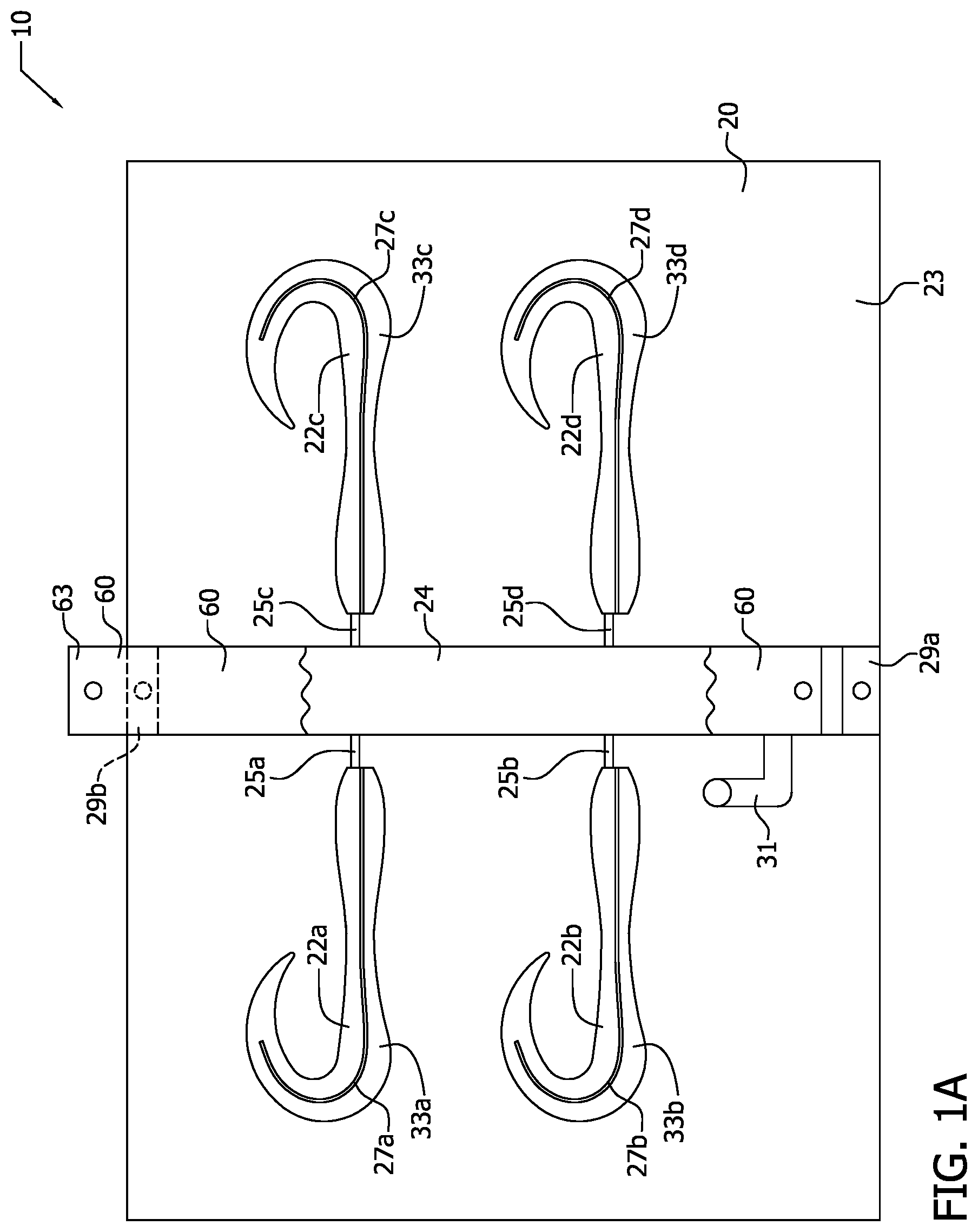
A illustrates by plan view a die portion of an exemplary implementation of a mold apparatus;
B illustrates by plan view a complementary die portion of the exemplary implementation of the mold apparatus;
C illustrates by perspective view an exemplary assembly comprising the die portion of the exemplary implementation of the mold apparatus of A in mechanical cooperation with the complementary die portion of the exemplary implementation of the mold apparatus of B ;
illustrates by cross-sectional elevation view portions of the exemplary implementation of the mold apparatus;
illustrates by another cross-sectional elevation view portions of the exemplary implementation of the mold apparatus;
illustrates by cross-sectional plan view portions of the exemplary implementation of the mold apparatus;
illustrates by yet another cross-sectional elevation view portions of the exemplary implementation of the mold apparatus;
illustrates by process flow chart exemplary method of operation of the exemplary mold apparatus;
A illustrates by plan view an exemplary object manufactured by the exemplary mold apparatus and exemplary methods of operation; and
B illustrates by cross-sectional view portions of the exemplary object of A .
The Figures are exemplary only, and the implementations illustrated therein are selected to facilitate explanation. The number, position, relationship and dimensions of the elements shown in the Figures to form the various implementations described herein, as well as dimensions and dimensional proportions to conform to specific force, weight, strength, flow and similar requirements are explained herein or are understandable to a person of ordinary skill in the art upon study of this disclosure. Where used in the various Figures, the same numerals designate the same or similar elements. Furthermore, when the terms “top,” “bottom,” “right,” “left,” “forward,” “rear,” “first,” “second,” “inside,” “outside,” and similar terms are used, the terms should be understood in reference to the orientation of the implementations shown in the drawings and are utilized to facilitate description thereof. Use herein of relative terms such as generally, about, approximately, essentially, may be indicative of engineering, manufacturing, or scientific tolerances such as ±0.1%, ±1%, ±2.5%, ±5%, or other such tolerances, as would be readily recognized by those of ordinary skill in the art upon study of this disclosure.
DETAILED DESCRIPTION OF THE INVENTION
The mold apparatus disclosed herein is configured for simultaneous communication of a resin having a color and a complementary resin having a complementary color into a mold cavity without intermixing between the resin and the complementary resin in order to form an object wherein the color is essentially separated from the complementary color, in various aspects. While the color and the complementary color differ from one another, the resin and the complementary resin may comprise essentially the same material except for color, in various aspects. In various aspects, the object formed by the mold apparatus may be configured as a fishing lure body, which is a molded portion of a fishing lure. The fishing lure includes the fishing lure body and the fishing lure may further include a hook, an attachment such as a swivel, streamers, and so forth disposed about the fishing lure body. The fishing lure body has a top and a bottom, and the top is of the color and the bottom is of the complementary color, in various aspects.
In various aspects, a barrier and a complementary barrier are aligned with one another to separate the mold cavity in part into a first mold sub-cavity and a second mold sub-cavity. The barrier and the complementary barrier aid in preventing intermixing of the resin with the complementary resin as the resin and complementary resin are communicated into the mold thereby enhancing separation of the color from the complementary color in the object along a color divide, in various aspects. The resulting object has two colors in lamination with one another along the color divide.
Resin and complementary resin may be a material convertible into polymer as used in molding an object formed of polymer, as would be readily understood by those of ordinary skill in the art upon study of this disclosure. Resin may include various catalysts and other additives, in various aspects. Fluidly communicable resin may refer to resin, for example, in a liquid, flowable, molten, or fluid state. Resin may be fluidly communicated into the mold cavity by injection, by pouring, and so forth, as would be readily understood by those of ordinary skill in the art upon study of this disclosure. Cured resin refers to resin that has solidified from being fluidly communicable into a solid thereby forming an object that is solid. Cured resin is polymerized and may include cross-linked polymer chains. Cure and curing refer to solidification from being fluidly communicable into the polymerized solid. Resin may be fluidly communicable under ambient conditions or may be rendered fluidly communicable by heating, in various aspects. Curing may be accomplished by heating, cooling, or combinations thereof, in various aspects. Exemplary resins may include, for example, plastisol—a colloidal dispersion of polymer particles in a liquid plasticizer. The polymer particles of plastisol absorb the plasticizer, for example, when heated to around 180° C., which causes the polymer particles to swell and fuse together thereby forming a viscous gel. The viscous gel is then cured by cooling below, for example, about 60° C. to form a flexible plasticized solid object. In various aspects, the polymer particles of plastisol comprise polyvinyl chloride. In various aspects, the object formed from plastisol may have a Shore hardness in a range of from about 5 to about 80 on the Shore A scale. Note that plastisol should be considered as exemplary only and not limiting.
In various aspects, mold apparatus disclosed herein may be used in resin casting wherein the mold cavity is filled with a flowable resin that cures upon application of heat. In various aspects, mold apparatus disclosed herein may be used in injection molding wherein flowable resin is injected into the mold cavity. The heated flowable resin in the mold cavity is then cured by reducing the temperature. Of course, mold apparatus and related methods of use and manufactures disclosed herein may be used in conjunction with various other materials, molding processes, and manufactures, as would be readily recognized by those of ordinary skill in the art upon study of this disclosure.
A, 1 B and 1 C illustrate exemplary mold apparatus 10 , with A illustrating die 20 , B illustrating complementary die 40 , and C illustrating die 20 and complementary die 40 in mechanical cooperation with one another with surface 23 of die 20 biased against surface 43 of die 40 thereby forming assembly 17 .
As illustrated in A , die 20 includes cavities 22 a, 22 b, 22 c, 22 d defined by cavity surfaces 33 a, 33 b, 33 c, 33 d, respectively, recessed in surface 23 , and each cavity surface 33 a, 33 b, 33 c, 33 d is shaped at least in part as a negative impression of portions of object 80 (see A, 7 B ) being manufactured. Note that this implementation, which is offered for explanatory purposes, illustrates four cavities 22 a, 22 b, 22 c, 22 d so that four objects 80 may be molded simultaneously. It should be understood that die 20 may include any number of cavities, such as cavities 22 a, 22 b, 22 c, 22 d, for simultaneous molding of any number of objects, such as object 80 , as would be readily recognized by those of ordinary skill in the art upon study of this disclosure. Also, object 80 is configured as a fishing lure body for purposes of explanation. It should be understood the object, such as object 80 , and, thus, cavities, such as cavities 22 a, 22 b, 22 c, 22 d, may assume various shapes as may be required for various and sundry manufactures, as would be readily recognized by those of ordinary skill in the art upon study of this disclosure.
Divider 60 may be affixed to die 20 to enclose channel 24 with surface 61 thereby defining passage 35 (see ). When so affixed, surface 63 of divider 60 is continuous with surface 23 of die 20 . Divider 60 is illustrated in A as partially received by die 20 with intermediate portions cut-away for explanatory purposes. Channel 24 is terminated by blocks 29 a, 29 b and divider may be affixed to blocks 29 a, 29 b by one or more fasteners (not shown) in order to affix removably divider 60 at least in part to die 20 . Holes are illustrated in blocks 29 a, 29 b and corresponding holes are illustrated in divider 60 for reception of such fasteners. Die 20 including channel 24 may be configured to cooperate with divider 60 in various ways, as would be readily recognized by those of ordinary skill in the art upon study of this disclosure. Because channel 24 is terminated by blocks 29 a, 29 b, channel 24 , and, thus passage 35 , is internal to die 20 . Blocks 29 a, 29 b may be recessed from surface 23 to accommodate divider 60 so that surface 63 of divider 60 matches surface 23 of die 20 when divider 60 is affixed thereto. Input passage 31 , which is formed as a channel in surface 23 terminating at a hole passing between surfaces 21 , 23 of die 20 , allows for fluid communication of flowable resin 81 (see ) between surface 21 of die 20 and passage 35 . Divider 60 may be removed, for example, to allow cleaning of divider 60 and channel 24 .
As illustrated in A , barrier 27 a is formed as a part of cavity surface 33 a, and barrier 27 a extends from channel 24 through portions of cavity 22 a to separate cavity 22 a into two portions, as illustrated. Portions of cavity surface 33 a formed as a negative impression of portions of object 80 also include barrier 27 a, as illustrated. Note that barrier 27 a is curved, in this implementation, but barrier 27 a may be straight or have various other configurations depending upon the shape of cavity surface 33 a, in various other implementations. Also, note that barrier 27 a extends from passage 35 only partially through cavity 22 a, in this implementation, but barrier 27 a may extend variously into cavity 22 a including completely through cavity 22 a from passage 35 , in various other implementations. Other portions of cavity surface 33 a form, in part, cavity passage 25 a for fluid communication of cavity 22 a with passage 35 . Note that cavity passage 25 a is disposed to one side of barrier 27 a.
Cavities 22 b, 22 c, 22 d are configured similarly to cavity 22 a, in this implementation. As illustrated, cavity 22 b is separated into two portions by barrier 27 b, cavity 22 c is separated into two portions by barrier 27 c, and cavity 22 d is separated into two portions by barrier 27 d. Cavity passages 25 b, 25 c, 25 d formed in part by portions of cavity surfaces 33 b, 33 c, 33 d allow fluid communication between cavities 22 b, 22 c, 22 d, respectively, and passage 35 . Note that cavity passages 25 b, 25 c, 25 d are disposed to one side of barriers 27 b, 27 c, 27 d, respectively.
As illustrated in B , complementary die 40 includes complementary channel 44 terminated by blocks 49 a, 49 b. When complementary die 40 is biased against die 20 in mechanical cooperation with die 20 to form assembly 17 (see C ), surface 63 of divider 60 encloses channel 44 to define complementary passage 55 (see ). Thus, divider 60 separates passage 35 from complementary passage 55 . Complementary passage 55 is terminated by blocks 49 a, 49 b, so that complementary passage 55 is internal to complementary die 40 . Input passage 51 , which is formed as a channel in complementary surface 43 terminating at a hole passing between surface 41 and complementary surface 43 of complementary die 40 , allows for fluid communication of complementary resin 83 (see ) between surface 41 of complementary die 40 and complementary passage 55 .
As illustrated in B , complementary die 40 includes complementary cavities 42 a, 42 b, 42 c, 42 d defined by complementary cavity surfaces 53 a, 53 b, 53 c, 53 d recessed in complementary surface 43 of complementary die 40 and shaped as a negative impression of other portions of exemplary object 80 . Thus, in this implementation, cavity surfaces 33 a, 33 b, 33 c, 33 d in combination with complementary cavity surfaces 53 a, 53 b, 53 c, 53 d, respectively, are shaped as entire surfaces of object 80 .
As illustrated in B , complementary cavity 42 a fluidly communicates with complementary passage 55 (also see , 3 ) via complementary passage 45 a formed in part by portions of complementary cavity surface 53 a. Complementary barrier 47 a is formed as a part of complementary cavity surface 53 a, and complementary barrier 47 a extends from complementary channel 44 through portions of complementary cavity 42 a to separate complementary cavity 42 a into two portions, as illustrated. Complementary passage 45 a is set to one side of complementary barrier 47 a, as illustrated. Portions of cavity surface 53 a formed as a negative impression of other portions of object 80 include complementary barrier 47 a, as illustrated.
Complementary cavities 42 b, 42 c, 42 d are configured similarly to complementary cavity 42 a, in this implementation. As illustrated, complementary cavity 42 b is separated into two portions by complementary barrier 47 b, complementary cavity 42 c is separated into two portions by complementary barrier 47 c, and complementary cavity 42 d is separated into two portions by complementary barrier 47 d. Complementary barriers 47 a, 47 b, 47 c, 47 d are configured similarly to barriers 27 a, 27 b, 27 c, 27 d so that complementary barriers 47 a, 47 b, 47 c, 47 d align with barriers 27 a, 27 b, 27 c, 27 d when surface 23 of die 20 is in biased engagement with complementary surface 43 of complementary die 40 in assembly 17 , illustrated in C . Complementary cavity passages 45 b, 45 c, 45 d allow fluid communication between complementary cavities 42 b, 42 c, 42 d, respectively, with complementary passage 55 . Note that complementary cavity passages 45 b, 45 c, 45 d are disposed to one side of complementary barriers 47 b, 47 c, 47 d, respectively.
Die 20 , complementary die 40 , and divider 60 may be comprised, for example, of aluminum or steel. Die 20 including cavities 22 a, 22 b, 22 c, 22 d, complementary die 40 including cavities 42 a, 42 b, 42 c, 42 d, and divider 60 may be variously cast, machined from stock, or fabricated in various other ways and combinations of ways, as would be readily understood by those of ordinary skill in the art upon study of this disclosure. While complementary cavities 42 a, 42 b, 42 c, 42 d mirror cavities 22 a, 22 b, 22 c, 22 d, in this exemplary implementation, complementary cavities 42 a, 42 b, 42 c, 42 d may be of different shape or may differ in various other ways from cavities 22 a, 22 b, 22 c, 22 d, for example, for molding of asymmetrically shaped objects, in other implementations.
C illustrates surface 23 of die 20 in biased engagement with complementary surface 43 of complementary die 40 to form assembly 17 . Surface 63 of divider 60 biases against blocks 49 a, 49 b of complementary die 40 . Die 20 and complementary die 40 may be separably biased with one another using, for example, various fasteners (e.g., screws, bolts, clamps, etc.; not shown), or biased against each other hydraulically or pneumatically. Divider 60 is affixed to die 20 to enclose channel 24 thereby defining passage 35 and to enclose channel 44 with surface 63 thereby defining complementary passage 55 , in exemplary assembly 17 . Input passage 31 formed in die 20 fluidly communicates between surface 21 and passage 35 and input passage 51 formed in complementary die 40 fluidly communicates between surface 41 and complementary passage 55 , in this implementation. Note that passage 35 , and complementary passage 55 are enclosed by blocks 29 a, 49 a, respectively, as illustrated, (and also by blocks 29 b, 49 b ) so that passage 35 and complementary passage 55 are internal to assembly 17 and accessible by input passages 31 , 51 , respectively.
In exemplary assembly 17 , cavities 22 a, 22 b, 22 c, 22 d face complementary cavities 42 a, 42 b, 42 c, 42 d, respectively, to define mold cavities 72 a, 72 b, 72 c, 72 d. Cavity surfaces 33 a combined with complementary cavity surface 53 a define mold cavity 72 a, cavity surface 33 b combined with complementary cavity surface 53 b define mold cavity 72 b, cavity surface 33 c combined with complementary cavity surface 53 c define mold cavity 72 c, and cavity surface 33 d combined with complementary cavity surface 53 d define mold cavity 72 d, in this implementation. Mold cavity 72 a is separated in part into first mold sub-cavity 76 a and second mold sub-cavity 78 a by barrier 27 a and complementary barrier 47 a, in this implementation. Mold cavity 72 b is separated in part into first mold sub-cavity 76 b and second mold sub-cavity 78 b by barrier 27 b and complementary barrier 47 b, in this implementation. Mold cavity 72 c is separated in part into first mold sub-cavity 76 c and second mold sub-cavity 78 c by barrier 27 c and complementary barrier 47 c, in this implementation. Mold cavity 72 d is separated in part into first mold sub-cavity 76 d and second mold sub-cavity 78 d by barrier 27 d and complementary barrier 47 d, in this implementation. Note that barrier 27 a is longitudinally aligned with complementary barrier 47 a with both barrier 27 a and complementary barrier 47 a extending the same length into mold cavity 72 a. Similar to barrier 27 a and complementary barrier 47 a, barrier 27 b is longitudinally aligned with complementary barrier 47 b, barrier 27 c is longitudinally aligned with complementary barrier 47 c, and barrier 27 d is longitudinally aligned with complementary barrier 47 d, to separate mold cavities 72 b, 72 c, 72 d, respectively, in a similar manner, as illustrated.
illustrates a cross-section of portions of assembly 17 with cavity passages 25 a, and complementary cavity passage 45 a as viewed from passage 35 and complementary passage 55 , respectively. Passage 35 is defined by surface 61 of divider 60 and channel 24 formed in die 20 , and complementary passage 55 is defined by surface 63 of divider 60 and complementary channel 44 , as illustrated. Surface 63 of divider 60 matches surface 23 of die 20 , in this implementation. As illustrated in , cavity passage 25 a, and complementary cavity passage 45 a are offset with respect to one another. Cavity passage 25 a is bounded by portions of cavity surface 33 a and by complementary surface 43 of complementary die 40 so that cavity passage 25 a communicates fluidly only with passage 35 and not with complementary passage 55 , as illustrated. Similarly, complementary cavity passage 45 a is bounded by portions of complementary cavity surface 53 a and by surface 23 of die 20 so that complementary cavity passage 45 a communicates fluidly only with complementary passage 55 and not with passage 35 , as illustrated.
In exemplary assembly 17 as illustrated in , resin 81 having color 82 may be fluidly communicated from passage 35 into first mold sub-cavity 76 a of mold cavity 72 a through passage 25 a on one side of barrier 27 a and complementary barrier 47 a, and complementary resin 83 having color 84 may be fluidly communicated from complementary passage 55 into second mold sub-cavity 78 a of mold cavity 72 a through passage 45 a on another side of barrier 27 a and complementary barrier 47 a. Color 82 differs from complementary color 84 , in this implementation. Barrier 27 a and complementary barrier 47 a inhibit mixing of color 82 of resin 81 in first mold sub-cavity 76 a of mold cavity 72 a with color 84 of complementary resin 83 in second mold sub-cavity 78 a of mold cavity 72 a as resin 81 and complementary resin 83 are communicated fluidly simultaneously into first mold sub-cavity 76 a and second mold sub-cavity 78 a.
illustrates another cross-section of assembly 17 . As illustrated in , complementary resin 83 having complementary color 84 is fluidly communicated from complementary passage 55 into second mold sub-cavity 78 a through passage 45 a and from complementary passage 55 into second mold sub-cavity 78 c through passage 45 c. Resin 81 having color 82 is fluidly communicated from passage 35 through passage 25 a into first mold sub-cavity 76 a, and from passage 35 through passage 25 c into first mold sub-cavity 76 c, as illustrated in phantom in . Note that barriers 27 a, 27 b and complementary barriers 47 a, 47 b are not included in for clarity of explanation.
Thus, in this exemplary implementation, resin 81 with color 82 is fluidly communicated from passage 35 into first mold sub-cavities 76 a, 76 b, 76 c, 76 d of mold cavities 72 a, 72 b, 72 c, 72 d, respectively, and complementary resin 83 with color 84 is fluidly communicated simultaneously from complementary passage 55 into second mold sub-cavities 78 a, 78 b, 78 c, 78 d of mold cavities 72 a, 72 b, 72 c, 72 d, respectively. Portions of object 80 formed in first mold sub-cavity 76 a have color 82 and portions of object 80 formed in second mold-sub-cavity 78 a have color 84 with a color divide 87 formed therebetween with substantially no intermixing of color 82 with color 84 along color divide 87 (see A, 7 B ).
Barrier 27 b and complementary barrier 47 b inhibit mixing of resin 81 with complementary resin 83 as resin 81 and complementary resin 83 are communicated fluidly simultaneously into first mold sub-cavity 76 b and second mold sub-cavity 78 b, respectively, of mold cavity 72 b. Barrier 27 c and complementary barrier 47 c inhibit mixing of resin 81 with complementary resin 83 as resin 81 and complementary resin 83 are communicated fluidly simultaneously into first mold sub-cavity 76 c and second mold sub-cavity 78 c, respectively, of mold cavity 72 c. Barrier 27 d and complementary barrier 47 d inhibit mixing of resin 81 with complementary resin 83 as resin 81 and complementary resin 83 are communicated fluidly simultaneously into first mold sub-cavity 76 d and second mold sub-cavity 78 d, respectively, of mold cavity 72 d.
illustrates mold cavity 72 a, with mold cavities 72 b, 72 c, 72 d being configured similarly to mold cavity 72 a, in this implementation. As illustrated in , mold cavity 72 a of assembly 17 is separated in part into first mold sub-cavity 76 a and second mold sub-cavity 78 a by barrier 27 a and complementary barrier 47 a. Barrier 27 a is coextensive with complementary barrier 47 a and barrier 27 a is aligned with complementary barrier 47 a, as illustrated. Resin 81 with color 82 is being fluidly communicated into first mold sub-cavity 76 a through passage 25 a, and complementary resin 83 with complementary color 84 is being fluidly communicated into second mold sub-cavity 78 a through passage 45 a, as illustrated in . Resin 81 is fluidly communicated at pressure p 1 and temperature T 1 , and complementary resin 83 is fluidly communicated at complementary pressure p 2 and complementary temperature T 2 , as illustrated. Resin 81 and complementary resin 83 are being fluidly communicated simultaneously, in this implementation. Resin 81 may be formed of the same material as complementary resin 83 with resin 81 differing from complementary resin 83 by differing of color 82 with complementary color 84 . Pressure p 1 may be approximately equal to pressure p 2 and temperature T 1 may be approximately equal to temperature T 2 so that the fluid properties (e.g., density, viscosity) of resin 81 and complementary resin 83 are essentially the same.
further illustrates mold cavity 72 a including first sub-cavity 76 a separated partly from second sub-cavity 78 a by barrier 27 a and complementary barrier 47 a in assembly 17 . Barrier 27 a matches complementary barrier 47 a in longitudinal extent through mold cavity 72 a, and barrier 27 a is longitudinally aligned with complementary barrier 47 a when surface 23 of die 20 and complementary surface 43 of complementary die are in biased engagement with one another in assembly 17 . Note that barrier 27 a extends only partway from surface 33 a of cavity 22 a to plane 37 defined by surface 23 of die 20 so that barrier 27 a is offset from plane 37 by gap 39 , as illustrated. Gap 39 may or may not vary longitudinally along barrier 27 a, in various implementations. Similarly, complementary barrier 47 a extends only partway from surface 53 a of cavity 42 a to complementary plane 57 defined by complementary surface 43 of complementary die 40 so that complementary barrier 47 a is offset from complementary plane 57 by gap 59 , as illustrated. Gap 59 may or may not vary longitudinally along complementary barrier 47 a, in various implementations. Barrier 27 a is in spaced relation with complementary barrier 47 a separated by gap 39 plus gap 59 when surface 23 of die 20 and complementary surface 43 of complementary die 40 are in biased engagement with one another, as illustrated. Thus, cavity portion 76 a is only partially separated from cavity portion 78 a by barrier 27 a and complementary barrier 47 a, in this implementation. This allows for connectedness between portions of the object molded in cavity portion 76 a with portions of the object molded in cavity portion 78 a by, for example, material in gap 39 plus gap 59 .
An exemplary method of operation 500 of a mold apparatus, such as mold apparatus 10 , is illustrated in . Method 500 is entered at step 501 .
At step 505 , a divider, such as divider 60 , is affixed to a die, such as die 20 .
At step 510 , the die is placed in biased engagement with a complementary die, such as complementary die 40 .
At step 515 a resin having a color, such as resin 81 having color 82 , is fluidly communicated into a first mold sub-cavity, such as first mold sub-cavity 76 a, 76 b, 76 c, 76 d, while a complementary resin having a complementary color, such as complementary resin 83 having complementary color 84 , is simultaneously fluidly communicated into a second mold sub-cavity, such as second mold sub-cavity 78 a, 78 b, 78 c, 78 d. The second mold sub-cavity is separated in part from the first mold sub-cavity by barriers and complementary barriers, such as barriers 27 a, 27 b, 27 c, 27 d and complementary barriers 47 a, 47 b, 47 c, 47 d, respectively.
The resin and complementary resin may be melted (e.g., liquified) to be fluidly communicable by heat exchangers (not shown), pressurized (e.g., by compressed air), and then simultaneously communicated fluidly into the first mold sub-cavity and the second mold sub-cavity. The resin and the complementary resin may be comprised of the same material (e.g., plastisol) differing from one another only by color. The temperature and thus the density of the resin and the complementary resin are generally equivalent as the resin and the complementary resin are communicated into the first mold sub-cavity and the second mold sub-cavity, in various implementations. The flow rates of the resin and complementary resin are monitored and controlled to ensure that the first mold sub-cavity and the second mold sub-cavity are filled generally simultaneously, thus forming color divide 87 as a separation between the color 82 and the complementary color 84 (see A, 7 B ), in various implementations.
At step 520 , the resin and the complementary resin are allowed to cure thereby forming solid object(s), such as object 80 . Several objects may be formed simultaneously.
At step 525 , the object(s) are released from the die and the complementary die.
Method 500 terminates at step 531 .
A illustrates exemplary object 80 molded by exemplary method 500 using a mold apparatus, such as exemplary mold apparatus 10 . Object 80 may be formed in any of mold cavity 72 a, 72 b, 72 c, 72 d. Exemplary object 80 is configured as a fishing lure body, and exemplary object 80 has the form of a shrimp, in this illustrative implementation. Hook(s), connector, etc. may then be added to exemplary object 80 to form a fishing lure. As illustrated in A , object 80 has been released from the mold cavity and resin 81 , and complementary resin 83 , from which object 80 has been formed, are cured so that object 80 is solid. As illustrated, object 80 includes color 82 separated from complementary color 84 along color divide 87 , with color 82 forming top 91 of object 80 and complementary color 84 forming bottom 93 of object 80 . Color divide 87 generally coincides with barrier 27 a, 27 b, 27 c, 27 d and complementary barrier 47 a, 47 b, 47 c, 47 d in mold cavity 72 a, 72 b, 72 c, 72 d, respectively. Mixing between color 82 and complementary color 84 along color divide 87 is minimized so that color divide 87 defines a sharp delineation between color 82 and complementary color 84 .
B illustrates a cross-sectional slice through object 80 with color 82 separated from complementary color 84 along color divide 87 . Object 80 includes mold marks 89 a, 89 b as impressions in object surface 86 formed by a barrier and a complementary barrier in a mold cavity, such as barrier 27 a, 27 b, 27 c, 27 d and complementary barrier 47 a, 47 b, 47 c, 47 d in mold cavity 72 a, 72 b, 72 c, 72 d, respectively. Color divide 87 , that separates color 82 from complementary color 84 passes between mold marks 89 a, 89 b so as to be coincident with mold marks 89 a, 89 b, as illustrated in B .
The foregoing discussion along with the Figures discloses and describes various exemplary implementations. These implementations are not meant to limit the scope of coverage, but, instead, to assist in understanding the context of the language used in this specification and in the claims. The Abstract is presented to meet requirements of 37 C.F.R. §1.72(b) only. Accordingly, the Abstract is not intended to identify key elements of the apparatus, methods, and manufactures disclosed herein or to delineate the scope thereof. Upon study of this disclosure and the exemplary implementations herein, one of ordinary skill in the art may readily recognize that various changes, modifications and variations can be made thereto without departing from the spirit and scope of the inventions as defined in the following claims.
Figures (7)
Citations
This patent cites (28)
- US3950483
- US4141170
- US6554605
- US20060177668
- US20060214324
- US20190021300
- US20200315152
- US20210137084
- US207344970
- US207344989
- US210362194
- US212684533
- US102012025039
- US2286702
- US2290149
- US2747269
- US1157282
- US58191139
- US61104816
- US0820040
- US3047530
- US10276620
- US10276621
- US2009184278
- US2011116087
- US20190051101
- USWO7901111
- USWO2009106634