Method for Cleaning Vaporizer and Vaporization Apparatus
Abstract
A method for cleaning a vaporizer that vaporizes, at normal temperature and pressure, a source material in a liquid state, and supplies the vaporized source material to a reactor through a supply pipe, includes a cleaning step of passing the source material to the vaporizer while maintaining the source material in a liquid state to clean the vaporizer.
Claims (8)
1. A method for cleaning a vaporizer that vaporizes, at normal temperature and pressure, octamethylcyclostetrasiloxane (OMCTS) in a liquid state as a source material, and supplies the vaporized OMCTS to a reactor through a supply pipe, the method comprising a cleaning step of passing the OMCTS to the vaporizer while maintaining the OMCTS in a liquid state to clean the vaporizer by discharging a polymer of the OMCTS in a gel state, and a mixing step of mixing the OMCTS with a carrier gas to generate a mixed fluid, wherein the cleaning step is performed after the mixing step, and the cleaning step includes passing the mixed fluid to the vaporizer while maintaining, in a liquid state, the OMCTS contained in the mixed fluid to clean the vaporizer by discharging the polymer of the OMCTS in a gel state.
6. A vaporization apparatus comprising: a reservoir configured to store octamethylcyclotetrasiloxane (OMCTS) in a liquid state as a source material at normal temperature and pressure; a mixing chamber configured to mix the OMCTS in a liquid state and a carrier gas; a vaporizer configured to vaporize the OMCTS in a liquid state supplied with the carrier gas from the mixing chamber; a supply pipe through which a mixed fluid of the OMCTS vaporized in the vaporizer and the carrier gas is supplied to a reactor; and a recirculation pipe configured to return the OMCTS in a liquid state from the vaporizer to the reservoir.
Show 6 dependent claims
2. The method for cleaning the vaporizer according to claim 1 , wherein the cleaning step includes delivering at least part of the OMCTS in a liquid state used in the cleaning to the vaporizer again to clean the vaporizer by discharging the polymer of the OMCTS in a gel state.
3. The method for cleaning the vaporizer according to claim 1 , wherein the cleaning step includes passing the OMCTS to the supply pipe while maintaining the OMCTS in a liquid state to clean the supply pipe by discharging the polymer of the OMCTS in a gel state.
4. The method for cleaning the vaporizer according to claim 3 , wherein the cleaning step includes passing the OMCTS in a liquid state from the vaporizer to the supply pipe, wherein the supply pipe is located vertically downward of the vaporizer.
5. The method for cleaning the vaporizer according to claim 1 , wherein the OMCTS in a liquid state is pressure-fed to the vaporizer using a pump.
7. The vaporization apparatus according to claim 6 , wherein the recirculation structure is located vertically downward of the vaporizer.
8. The vaporization apparatus according to claim 6 , further comprising a pump configured to pressure-feed the OMCTS in a liquid state from the reservoir to the vaporizer without passing the OMCTS through the mixing chamber.
Full Description
Show full text →
CROSS-REFERENCE TO RELATED APPLICATION(S)
This application is a continuation of International Application No. PCT/JP2020/007978, filed on Feb. 27, 2020 which claims the benefit of priority of the prior Japanese Patent Application No. 2019-041840, filed on Mar. 7, 2019, the entire contents of which are incorporated herein by reference.
BACKGROUND
The present disclosure relates to a method for cleaning a vaporizer and a vaporization apparatus.
In the related art, a known manufacturing step vaporizes a liquid source material and allows the vaporized source material to undergo a chemical reaction. For example, an optical fiber manufacturing step includes a step of vaporizing a siloxane-based material as a liquid source material of silicon and allowing the vaporized source material to undergo a flame hydrolysis reaction using a burner in a reactor to generate glass microparticles.
For example, in Japanese Laid-open Patent publication No. 2017-36172, a siloxane-based material in a liquid state is used as a source material and introduced into a vaporizer together with a carrier gas to perform vaporization of the source material. Further, Japanese Unexamined Patent Application Publication No. 2014-517801 discloses introducing a siloxane-based material in a liquid state toward a vertical wall of an expansion chamber, the vertical wall being heated, to vaporize the siloxane-based material, using a vaporized portion of the siloxane-based material as a source material, and collecting an unvaporized portion of the siloxane-based material at a lower region of the expansion chamber and flushing the unvaporized portion of the siloxane-based material to a reservoir.
SUMMARY
There is a need for providing a method for cleaning a vaporizer and a vaporization apparatus that are capable of, even if a polymer of a source material is produced, easily removing the polymer.
According to an embodiment, a method for cleaning a vaporizer that vaporizes, at normal temperature and pressure, a source material in a liquid state, and supplies the vaporized source material to a reactor through a supply pipe, includes a cleaning step of passing the source material to the vaporizer while maintaining the source material in a liquid state to clean the vaporizer.
According to an embodiment, a vaporization apparatus incudes: a reservoir configured to store a source material in a liquid state at normal temperature and pressure; a mixer configured to mix the source material in a liquid state and a carrier gas; a vaporizer configured to vaporize the source material in a liquid state supplied from the mixer; a supply pipe through which a mixed fluid of the source material vaporized in the vaporizer and the carrier gas is supplied to outside; and a recirculation structure configured to return the source material in a liquid state from the vaporizer to the reservoir.
BRIEF DESCRIPTION OF DRAWINGS
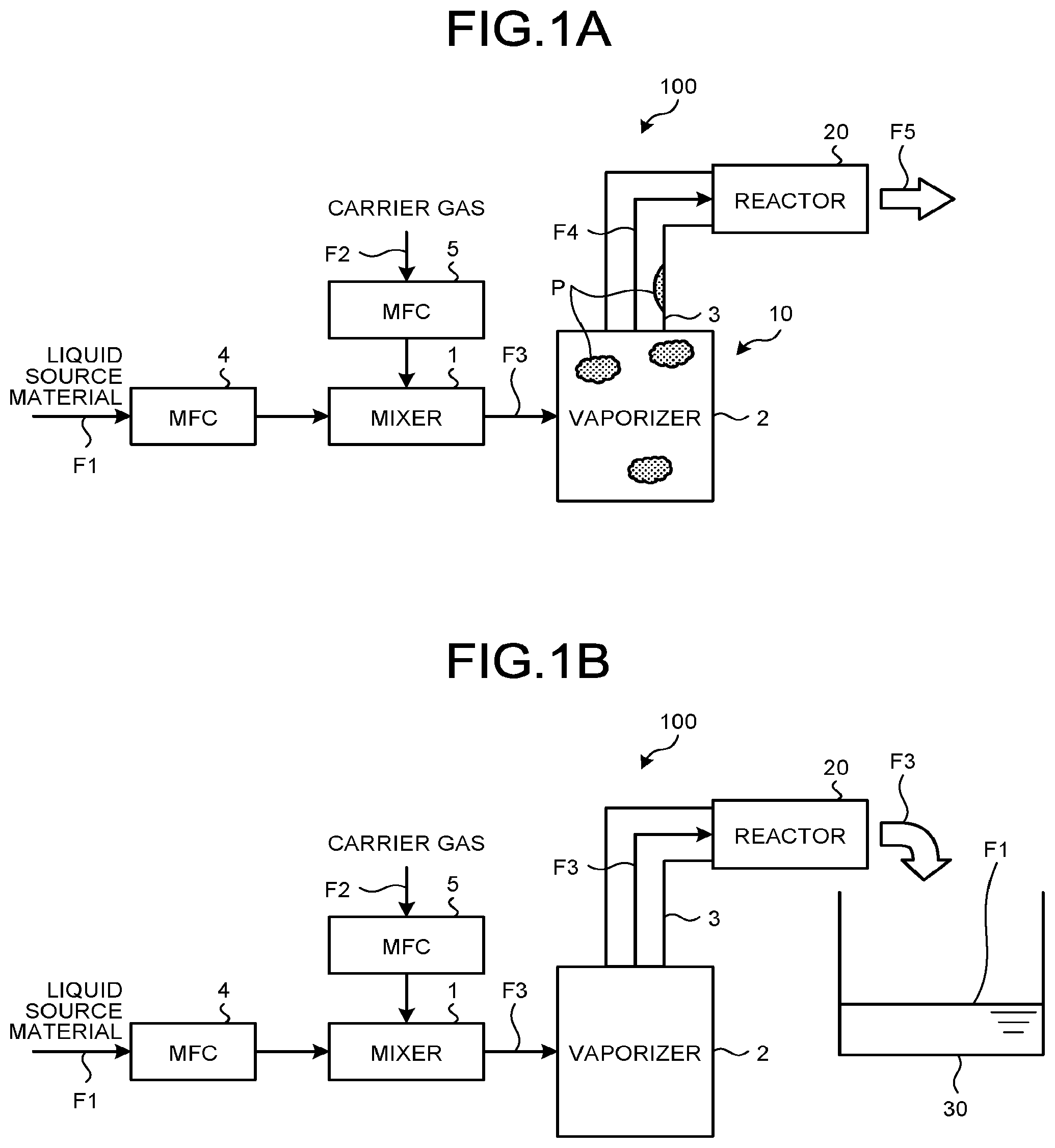
A is an explanatory diagram for explaining a method for cleaning a vaporization apparatus according to a first embodiment;
B is an explanatory diagram for explaining the method for cleaning the vaporization apparatus according to the first embodiment;
is an explanatory diagram for explaining a method for cleaning a vaporization apparatus according to a second embodiment;
is an explanatory diagram for explaining a method for cleaning a vaporization apparatus according to a third embodiment; and
is an explanatory diagram for explaining a method for cleaning a vaporization apparatus according to a fourth embodiment.
DETAILED DESCRIPTION
In the related art, in the method of Japanese Laid-open Patent publication No. 2017-36172, if a path downstream of an exit of the vaporizer cannot be maintained at a predetermined temperature, liquefaction of the siloxane-based material occurs. As a result, the liquefied siloxane-based material may be repeatedly polymerized to produce a polymer, and the produced polymer may be deposited inside the vaporizer. If such deposition progresses, a desired source material flow rate may not be obtained due to an increase in pressure loss inside the vaporizer. Moreover, once a polymer is produced inside the vaporizer, it takes time to remove the polymer. Thus, there is a problem of an increase in the running costs of the vaporizer and a vaporization apparatus provided with the vaporizer. Note that such polymer deposition can also occur in a supply pipe.
On the other hand, in the method of Japanese Unexamined Patent Application Publication No. 2014-517801, although only the vaporized source material can be easily delivered with a polymer excluded, the liquid source material cannot be efficiently vaporized in spite of the large scale of the vaporizer. Thus, there is a problem of an increase in material costs.
Hereinbelow, embodiments of the present disclosure will be described with reference to the drawings. Note that the present disclosure is not limited to the embodiments. Further, identical reference signs appropriately designate identical or corresponding elements throughout the drawings. Furthermore, in the drawings, illustration of a pipe through which fluid is delivered is appropriately omitted.
First Embodiment
A and 1 B are explanatory diagrams for explaining a method for cleaning a vaporization apparatus according to a first embodiment. A manufacturing apparatus 100 illustrated in A is an apparatus that manufactures a porous preform used in the manufacture of an optical fiber and includes a vaporization apparatus 10 and a reactor 20 .
The vaporization apparatus 10 includes a mixer 1 , a vaporizer 2 , a supply pipe 3 , and mass flow controllers (MFCs) 4 and 5 .
The MFCs 4 and 5 are control units for controlling the mass flow rate of fluid. Each of the MFCs 4 and 5 includes a mass flowmeter which measures the mass flow rate, and a solenoid valve whose opening degree is automatically adjusted on the basis of a result of the measurement of the mass flowmeter.
The MFC 4 supplies, to the mixer 1 , a source material fluid F 1 which is a liquid source material supplied from a supply source while controlling the mass flow rate of the source material fluid F 1 . The source material fluid F 1 is, for example, octamethylcyclotetrasiloxane (OMCTS), which is a siloxane-based material. OMCTS has a melting point of 18° C. and a boiling point of 176° C. at normal pressure and is in a liquid state at normal temperature and pressure. The siloxane-based material is not limited to OMCTS and may be, for example, decamethylcyclopentasiloxane (DMCPS).
The MFC 5 supplies, to the mixer 1 , a carrier gas F 2 which is a carrier gas supplied from a supply source while controlling the mass flow rate of the carrier gas F 2 . The carrier gas F 2 is, for example, nitrogen gas (N 2 gas).
The mixer 1 is, for example, a mixing chamber. The mixer 1 mixes the source material fluid F 1 and the carrier gas F 2 inside a chamber and supplies the mixture as a mixed fluid F 3 to the vaporizer 2 .
The vaporizer 2 includes an internal pipe through which the mixed fluid F 3 is delivered and a heater which heats the internal pipe, the internal pipe and the heater being built in the vaporizer 2 . The vaporizer 2 heats the internal pipe through which the mixed fluid F 3 is delivered to vaporize a source material in a liquid state contained in the mixed fluid F 3 . The vaporizer 2 is configured so as to be capable of maintaining the temperature inside the internal pipe at the boiling point of the source material or higher, for example, at approximately 180° C. in the case of OMCTS to vaporize the source material in a liquid state. The vaporizer 2 delivers a mixed fluid F 4 with the source material vaporized to the supply pipe 3 .
The mixed fluid F 4 is delivered to the reactor 20 disposed outside the vaporization apparatus 10 through the supply pipe 3 . The supply pipe 3 is preferably heated by the heater so that the source material contained in the mixed fluid F 4 is not liquefied.
The reactor 20 includes a reaction vessel and a burner disposed inside the reaction vessel. For example, a source material other than the OMCTS, diluent gas such as argon, combustion gas which supports combustion, and dopant which is added to soot to be manufactured are also supplied to the reactor 20 . The reactor 20 allows the source materials including the OMCTS to undergo a flame hydrolysis reaction using the burner to generate glass microparticles and deposits the generated glass microparticles on a target rod to manufacture the soot. Note that a source material and glass particles that have not been used in the manufacture of the soot are fed to a gas purifier using a suction pump, and the gas purifier removes the source material and the glass particles.
A polymer P of the OMCTS may be deposited in a gel state inside the vaporizer 2 or inside the supply pipe 3 . Thus, a cleaning method according to the first embodiment as illustrated in B is executed to remove the polymer P.
First, the mixer 1 performs a mixing step of mixing the source material fluid F 1 and the carrier gas F 2 to generate the mixed fluid F 3 and supplies the mixed fluid F 3 to the vaporizer 2 .
The vaporizer 2 passes the mixed fluid F 3 through the internal pipe while maintaining, in a liquid state, the source material fluid F 1 contained in the mixed fluid F 3 by retaining the temperature of the mixed fluid F 3 . Accordingly, a cleaning step is executed. The vaporizer 2 is configured so as to be capable of keeping the temperature inside the pipe at a temperature lower than the boiling point of the source material and higher than the melting point of the source material, for example, at approximately 35° C. in the case of OMCTS to maintain the source material fluid F 1 in a liquid state. As a result, the polymer P deposited in the vaporizer 2 is appropriately and easily removed by the source material fluid F 1 in a liquid state. The vaporizer 2 delivers the mixed fluid F 3 used in the cleaning to the supply pipe 3 .
The supply pipe 3 passes therethrough the mixed fluid F 3 while maintaining, in a liquid state, the source material fluid F 1 contained in the mixed fluid F 3 by retaining the temperature of the mixed fluid F 3 . Accordingly, the cleaning step is further executed. The supply pipe 3 is configured so as to be capable of keeping the temperature inside the pipe at a temperature lower than the boiling point of the source material and higher than the melting point of the source material, for example, at approximately 35° C. in the case of OMCTS to maintain the source material fluid F 1 in a liquid state. The mixed fluid F 3 used in the cleaning is discharged through the reactor 20 , and the source material fluid F 1 is stored in a reservoir 30 having a container shape.
According to the cleaning method according to the first embodiment, even if the polymer P is produced, the produced polymer P can be easily removed by passing the mixed fluid F 3 of the source material fluid F 1 in a liquid state and the carrier gas F 2 which is a carrier gas through the vaporizer 2 and the supply pipe 3 . Thus, the running costs of the vaporizer 2 and the vaporization apparatus 10 can be reduced.
Second Embodiment
is an explanatory diagram for explaining a method for cleaning a vaporization apparatus according to a second embodiment. A manufacturing apparatus 100 A illustrated in has a configuration in which the vaporization apparatus 10 is replaced with a vaporization apparatus 10 A in the configuration of the manufacturing apparatus 100 illustrated in .
The vaporization apparatus 10 A has a configuration in which the vaporizer 2 and the supply pipe 3 are replaced with a vaporizer 2 A and a supply pipe 3 A, respectively, in the configuration of the vaporization apparatus 10 . The vaporizer 2 A differs from the vaporizer 2 in that the vaporizer 2 A is connected to the supply pipe 3 A on the vertically downward side of the vaporizer 2 A. The supply pipe 3 A differs from the supply pipe 3 in that the supply pipe 3 A is located vertically downward of the vaporizer 2 A and connected to the reactor 20 .
In performing the cleaning method according to the second embodiment, as with the first embodiment, the mixer 1 performs a mixing step of mixing the source material fluid F 1 and the carrier gas F 2 to generate the mixed fluid F 3 and supplies the mixed fluid F 3 to the vaporizer 2 .
The vaporizer 2 passes the mixed fluid F 3 through the internal pipe while maintaining, in a liquid state, the source material fluid F 1 contained in the mixed fluid F 3 by retaining the temperature of the mixed fluid F 3 . Accordingly, as with the first embodiment, a polymer deposited inside the vaporizer 2 A is appropriately and easily removed. Further, since the vaporizer 2 A is connected to the supply pipe 3 A on the vertically downward side of the vaporizer 2 A, a polymer having a higher density than the mixed fluid F 3 is easily discharged by gravity. The vaporizer 2 A delivers the mixed fluid F 3 used in the cleaning to the supply pipe 3 A.
The supply pipe 3 A passes therethrough the mixed fluid F 3 while maintaining, in a liquid state, the source material fluid F 1 contained in the mixed fluid F 3 by retaining the temperature of the mixed fluid F 3 . Accordingly, as with the first embodiment, a polymer deposited inside the supply pipe 3 A is appropriately and easily removed. Further, since the supply pipe 3 A extends vertically downward from the vaporizer 2 A, the polymer is easily discharged by the gravity. Then, as with the first embodiment, the mixed fluid F 3 used in the cleaning is discharged through the reactor 20 , and the source material fluid F 1 is stored in the reservoir 30 having a container shape.
According to the cleaning method according to the second embodiment, in particular, the discharge of the polymer is facilitated using gravity. Thus, even if a polymer is produced, the produced polymer can be easily removed, and the running costs of the vaporizer 2 A and the vaporization apparatus 10 A can be reduced.
Third Embodiment
is an explanatory diagram for explaining a method for cleaning a vaporization apparatus according to a third embodiment. A manufacturing apparatus 100 B illustrated in has a configuration in which the vaporization apparatus 10 A is replaced with a vaporization apparatus 10 B in the configuration of the manufacturing apparatus 100 A illustrated in .
The vaporization apparatus 10 B has a configuration in which a three-way valve 6 a and a pump 6 b are added to the configuration of the vaporization apparatus 10 A.
The three-way valve 6 a is disposed between the mixer 1 and the vaporizer 2 A. When a manufacturing step using the reactor 20 is performed, the three-way valve 6 a functions to pass, to the vaporizer 2 A, a mixed fluid of the source material fluid F 1 and the carrier gas delivered from the mixer 1 .
The pump 6 b is configured to draw up the source material fluid F 1 in a liquid state stored in the reservoir 30 and pressure-feed the source material fluid F 1 to the three-way valve 6 a.
When the cleaning method according to the third embodiment is performed, the three-way valve 6 a passes the pressure-fed source material fluid F 1 to the vaporizer 2 A to clean the vaporizer 2 A and the supply pipe 3 A. At this time, the source material fluid F 1 has been pressurized and thus has a high flow velocity. As a result, it is possible to efficiently clean the vaporizer 2 A and the supply pipe 3 A. Then, as with the first embodiment, the source material fluid F 1 used in the cleaning is discharged through the reactor 20 and stored in the reservoir 30 . At least part of the source material fluid F 1 used in the cleaning may be drawn up by the pump 6 b and used in the cleaning of the vaporizer 2 A and the supply pipe 3 A again.
According to the cleaning method according to the third embodiment, in particular, the discharge of the polymer is facilitated using gravity. Thus, even if a polymer is produced, the produced polymer can be easily removed, and the running costs of the vaporizer 2 A and the vaporization apparatus 10 B can be reduced. Further, the cleaning efficiency is increased by pressure-feeding the source material fluid F 1 using the pump 6 b.
Furthermore, since the three-way valve 6 a is used in the third embodiment, it is not necessary to rearrange pipes between the manufacturing step and the cleaning step. However, when the cleaning step is performed without using the three-way valve 6 a , a pipe from the mixer 1 to the vaporizer 2 A may be detached, and a pipe may be directly connected from the pump 6 b to the vaporizer 2 A to pass the source material fluid F 1 through the pipe. In this case, additionally, the supply pipe 3 A may be detached from the vaporizer 2 A, and the source material fluid F 1 may be passed only to the vaporizer 2 A to perform cleaning.
Fourth Embodiment
is an explanatory diagram for explaining a method for cleaning a vaporization apparatus according to a fourth embodiment. A manufacturing apparatus 100 C illustrated in has a configuration in which the vaporization apparatus 10 B is replaced with a vaporization apparatus 10 C in the configuration of the manufacturing apparatus 100 B illustrated in .
The vaporization apparatus 10 C has a configuration in which the three-way valve 6 a is eliminated, the supply pipe 3 is replaced with a supply pipe 3 C, and a recirculation structure 7 and on-off valves 8 a , 8 b , and 8 c are added in the configuration of the vaporization apparatus 10 B.
The on-off valve 8 a is disposed between the mixer 1 and the vaporizer 2 A. When a manufacturing step using the reactor 20 is performed, the on-off valve 8 a is kept in an open state to function to pass, to the vaporizer 2 A, the mixed fluid F 3 of the source material fluid F 1 and the carrier gas F 2 delivered from the mixer 1 .
The pump 6 b is configured to draw up the source material fluid F 1 in a liquid state stored in the reservoir 30 and pressure-feed the source material fluid F 1 to the vaporizer 2 A through a confluence C between the on-off valve 8 a and the vaporizer 2 A. The on-off valve 8 b is disposed between the reservoir 30 and the pump 6 b . The on-off valve 8 c is disposed between the pump 6 b and the confluence C.
The recirculation structure 7 includes recirculation pipes 7 a , 7 b , and 7 c and a three-way valve 7 d which is connected to the recirculation pipes 7 a , 7 b , 7 c . The recirculation pipe 7 b is connected midway of the supply pipe 3 C.
When the manufacturing step using the reactor 20 is performed, the on-off valve 8 a is kept in an open state, whereas the on-off valves 8 b and 8 c are kept in a closed state. In this state, the mixed fluid F 3 delivered from the mixer 1 is passed to the vaporizer 2 A. The vaporizer 2 A and the supply pipe 3 C pass the mixed fluid F 3 to the reactor 20 while maintaining, in a gaseous state, the source material fluid F 1 contained in the mixed fluid F 3 .
On the other hand, when the cleaning method according to the fourth embodiment is performed, the on-off valve 8 a is kept in a closed state, whereas the on-off valves 8 b and 8 c are kept in an open state. The pump 6 b draws up the source material fluid F 1 stored in the reservoir 30 and pressure-feeds the source material fluid F 1 to the vaporizer 2 A through the on-off valves 8 b and 8 c and the confluence C. The pressure-fed source material fluid F 1 flows through the vaporizer 2 A and the supply pipe 3 C. Accordingly, the vaporizer 2 A and the supply pipe 3 C are efficiently cleaned.
Then, the source material fluid F 1 used in the cleaning is discharged through the reactor 20 and stored in the reservoir 30 through the recirculation pipe 7 a , the three-way valve 7 d , and the recirculation pipe 7 c . At least part of the source material fluid F 1 used in the cleaning is drawn up by the pump 6 b and used in the cleaning of the vaporizer 2 A and the supply pipe 3 C again.
Further, the three-way valve 7 d may be switched to pass the source material fluid F 1 from midway of the supply pipe 3 C to the reservoir 30 through the recirculation pipe 7 b , the three-way valve 7 d , and the recirculation pipe 7 c . At least part of the source material fluid F 1 used in the cleaning is drawn up by the pump 6 b and used in the cleaning of the vaporizer 2 A and the supply pipe 3 C again.
According to the cleaning method according to the fourth embodiment, in particular, the discharge of the polymer is facilitated using gravity. Thus, even if a polymer is produced, the produced polymer can be easily removed, and the running costs of the vaporizer 2 A and the vaporization apparatus 10 C can be reduced. Further, the cleaning efficiency is increased by pressure-feeding the source material fluid F 1 using the pump 6 b.
Furthermore, it is not necessary to rearrange pipes between the manufacturing step and the cleaning step in the fourth embodiment. In addition, since the recirculation structure 7 returns the source material fluid F 1 from the vaporizer 2 A to the reservoir 30 , the source material fluid F 1 can be efficiently collected.
As Example 1, a manufacturing apparatus having the configuration of the first embodiment was constructed, and OMCTS was used as the source material fluid. The OMCTS maintained at 35° C. was supplied to the vaporizer, and cleaning was performed for several hours. As a result, a polymer in a gel state was discharged from the reactor.
Further, as Example 2, a manufacturing apparatus having the configuration of the second embodiment was constructed, and OMCTS was used as the source material fluid. The OMCTS maintained at 35° C. was supplied to the vaporizer, and cleaning was performed for several hours. As a result, a polymer in a gel state was discharged from the reactor.
Note that the present disclosure is not limited to the embodiments described above. The present disclosure also includes an appropriate combination of the elements described above. Further effects and modifications can be easily derived by those skilled in the art. Thus, broader aspects of the present disclosure are not limited to the embodiments described above, and various changes can be made.
According to an embodiment, even if a polymer of a source material is produced, the polymer can be easily removed. Thus, an effect capable of reducing the running costs of the vaporizer and the vaporization apparatus is achieved.
The present disclosure can be suitably used in the cleaning of a vaporizer and the manufacture of an optical fiber.
Although the disclosure has been described with respect to specific embodiments for a complete and clear disclosure, the appended claims are not to be thus limited but are to be construed as embodying all modifications and alternative constructions that may occur to one skilled in the art that fairly fall within the basic teaching herein set forth.
Figures (4)
Citations
This patent cites (14)
- US5362328
- US5950646
- US7487806
- US10758874
- US20120276291
- US20170037501
- US20180071694
- US10-256242
- US11-229149
- US2005-060118
- US2006-223917
- US2014-517801
- US2017-036172
- USWO 94/21840